2014 NISSAN TEANA Pro pressure
[x] Cancel search: Pro pressurePage 2607 of 4801

HA-1
VENTILATION, HEATER & AIR CONDITIONER
C
D E
F
G H
J
K L
M
SECTION HA
A
B
HA
N
O P
CONTENTS
HEATER & AIR CONDITIONING SYSTEM
PRECAUTION ................ ...............................3
PRECAUTIONS .............................................. .....3
Precaution for Supplemental Restraint System
(SRS) "AIR BAG" and "SEAT BELT PRE-TEN-
SIONER" ............................................................. ......
3
Precaution for Work ..................................................3
Precaution for Working with HFC-134a (R-134a) ......3
Contaminated Refrigerant .........................................4
Precaution for Leak Detection Dye ...........................4
Precaution for Refrigerant Connection ......................4
Precaution for Service Equipment ....................... ......7
PREPARATION ............................................9
PREPARATION .............................................. .....9
Special Service Tool ........................................... ......9
HFC-134a (R-134a) Service Tool and Equipment ......9
Commercial Service Tool ........................................11
SYSTEM DESCRIPTION .............................13
REFRIGERATION SYSTEM .......................... ....13
Refrigerant Cycle ................................................ ....13
Refrigerant System Protection ................................13
Component Part Location ................................... ....14
BASIC INSPECTION ...................................15
DIAGNOSIS AND REPAIR WORKFLOW ..... ....15
Workflow ............................................................. ....15
SYMPTOM DIAGNOSIS ..............................17
HEATER AND AIR CONDITIONING SYSTEM
SYMPTOMS ................................................... ....
17
Symptom Table ................................................... ....17
REFRIGERATION SYSTEM SYMPTOMS .........18
Trouble Diagnosis For Unusual Pressure ........... ....18
Symptom Table .......................................................18
NOISE .................................................................20
Symptom Table ................................................... ....20
PERIODIC MAINTENANCE ........................21
REFRIGERANT ................................ .................21
Description ........................................................... ....21
Leak Test .................................................................21
Recycle Refrigerant .................................................23
Charge Refrigerant ..................................................23
OIL .....................................................................25
Description ...............................................................25
Inspection ................................................................25
Perform Oil Return Operation ..................................25
Oil Adjusting Procedure for Components Replace-
ment Except Compressor ........................................
25
Oil Adjusting Procedure for Compressor Replace-
ment ..................................................................... ....
26
PERFORMANCE TEST ....................................28
Inspection ................................................................28
REMOVAL AND INSTALLATION ...............30
COMPRESSOR .................................................30
COMPRESSOR ........ ..................................................30
COMPRESSOR : Exploded Vi ew ............................30
COMPRESSOR : Removal an d Installation ............30
MAGNET CLUTCH ................................................ ....31
MAGNET CLUTCH : Removal and Installation .......31
COOLER PIPE AND HOSE ..............................34
Exploded View .........................................................34
LOW-PRESSURE FLEXIBLE HOSE ..................... ....34
LOW-PRESSURE FLEXIBLE HOSE : Removal
and Installation .................................................... ....
34
HIGH-PRESSURE FLEXIBLE HOSE ........................35
HIGH-PRESSURE FLEXIBLE HOSE : Removal
and Installation .................................................... ....
35
Revision: November 20132014 Altima NAM
Page 2610 of 4801

HA-4
< PRECAUTION >
PRECAUTIONS
• Use only specified oil for the HFC-134a (R-134a) A/C system and HFC-134a (R-134a) components. If
oil other than that specified is used , compressor failure is likely to occur.
• The specified HFC-134a (R-134a) oi l rapidly absorbs moisture from the atmosphere. The following
handling precautions must be observed:
- When removing refrigerant components from a vehicle, immediately cap (seal) the component to
minimize the entry of moisture from the atmosphere.
- When installing refrigerant co mponents to a vehicle, do not remove the caps (unseal) until just
before connecting the components . Connect all refrigerant loop components as quickly as possible
to minimize the entry of moisture into system.
- Only use the specified oil from a sealed container. Immediately reseal containers of oil. Without
proper sealing, oil will become moisture saturat ed and should not be used.
- Avoid breathing A/C refrigerant and oil vapor or mist. Exposure may irritate eyes, nose and throat.
Remove HFC-134a (R-134a) from the A/C system usin g certified service equipment meeting require-
ments of SAE J2210 [HFC-134a (R-134a) recycling equipment], or J2209 [HFC-134a (R-134a) recy-
cling equipment], If accidental system discharge occurs, ventilate work area before resuming
service. Additional health and safety information may be obtain ed from refrigerant and oil manufac-
turers.
- Do not allow A/C oil to come in contact with styrofoam parts. Damage may result.
Contaminated RefrigerantINFOID:0000000009463911
If a refrigerant other than pure HFC-134a (R-134a) is identified in a vehicle, your options are:
• Explain to the customer that environmental regulations prohibit the release of contaminated refrigerant into
the atmosphere.
• Explain that recovery of the contaminated refri gerant could damage your service equipment and refrigerant
supply.
• Suggest the customer return the vehicle to the locati on of previous service where the contamination may
have occurred.
• If you choose to perform the repair, recover the refrigerant using only dedicated equipment and contain-
ers. Do not recover contamin ated refrigerant into your existing service equipment. If your facility does
not have dedicated recovery equipment, you may contact a local refrigerant product retailer for available ser-
vice. This refrigerant must be disposed of in acco rdance with all federal and local regulations. In addition,
replacement of all refrigerant system components on the vehicle is recommended.
• If the vehicle is within the warranty period, the air conditioner warranty is void. Please contact NISSAN Cus-
tomer Affairs for further assistance.
Precaution for Leak Detection DyeINFOID:0000000009463912
• The A/C system contains a fluorescent leak detection dye used for locating refrigerant leaks. An ultraviolet
(UV) lamp is required to illuminate the dye when inspecting for leaks.
• Always wear fluorescence enhancing UV safety goggles to protect your eyes and enhance the visibility of
the fluorescent dye.
• A compressor shaft seal should not be repaired because of dye seepage. The compressor shaft seal should only be repaired after confirming the leak with an electronic refrigerant leak detector (J-41995).
• Always remove any dye from the leak area after repairs are complete to avoid a misdiagnosis during a future
service.
• Do not allow dye to come into contact with painted body panels or interior components. If dye is spilled,
clean immediately with the approved dye cleaner. Fluoresc ent dye left on a surface for an extended period of
time cannot be removed .
• Do not spray the fluorescent dye cleaning agent on hot surfaces (engine exhaust manifold, etc.).
• Do not use more than one refrigerant dye bottle (1/4 ounce / 7.4 cc) per A/C system.
• Leak detection dyes for HFC-134a (R-134a) and HC-12 (R- 12) A/C systems are different. Do not use HFC-
134a (R-134a) leak detection dye in R-12 A/C systems or HC-12 (R-12) leak detection dye in HFC-134a (R-
134a) A/C systems or A/C system damage may result.
• The fluorescent properties of the dye will remain for ov er three (3) years unless a compressor failure occurs.
Precaution for Refrigerant ConnectionINFOID:0000000009463913
A new type refrigerant connection has been introduced to al l refrigerant lines except the following locations.
• Expansion valve to cooling unit
• Evaporator pipes to evaporator (inside cooling unit)
• Refrigerant pressure sensor
Revision: November 20132014 Altima NAM
Page 2611 of 4801
PRECAUTIONSHA-5
< PRECAUTION >
C
D E
F
G H
J
K L
M A
B
HA
N
O P
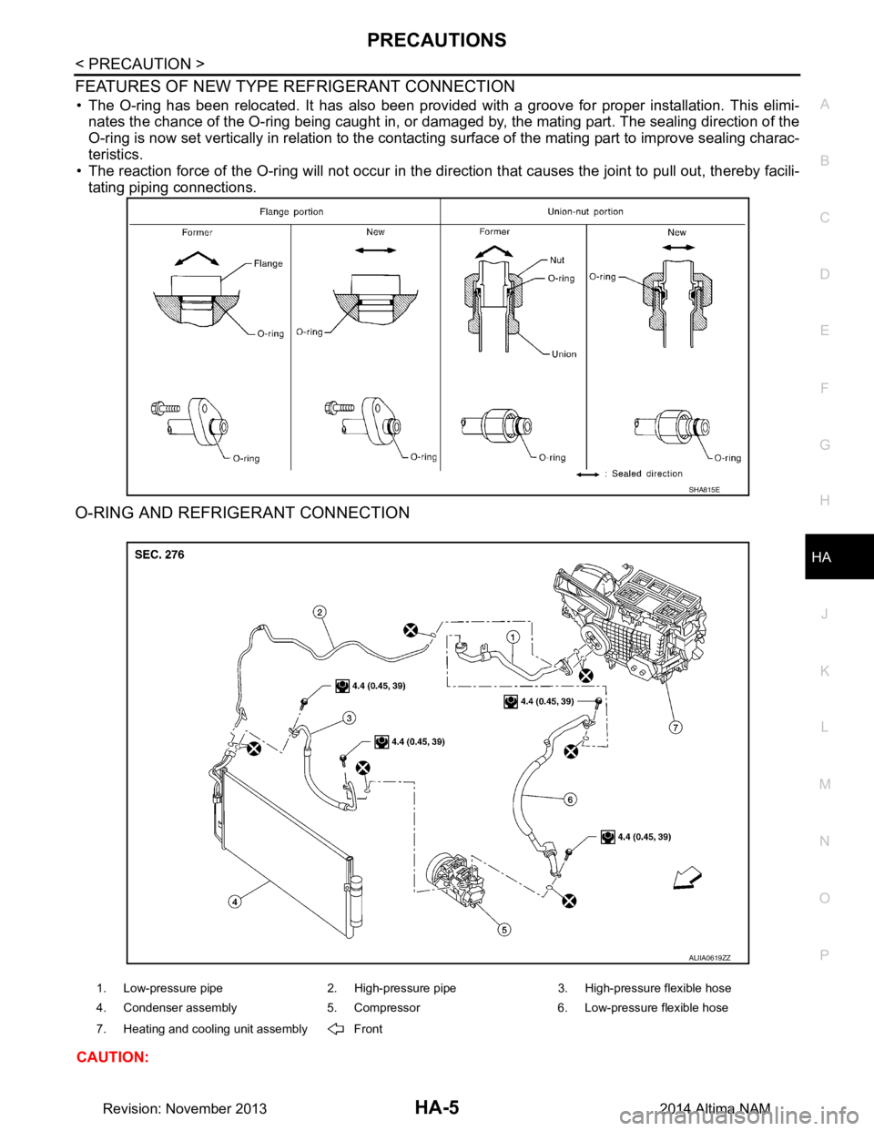
FEATURES OF NEW TYPE REFRIGERANT CONNECTION
• The O-ring has been relocated. It has also been provided with a groove for proper installation. This elimi- nates the chance of the O-ring being caught in, or damaged by, the mating part. The sealing direction of the
O-ring is now set vertically in relation to the contacti ng surface of the mating part to improve sealing charac-
teristics.
• The reaction force of the O-ring will not occur in the dire ction that causes the joint to pull out, thereby facili-
tating piping connections.
O-RING AND REFRIGERANT CONNECTION
CAUTION:
SHA815E
1. Low-pressure pipe 2. High-pressure pipe 3. High-pressure flexible hose
4. Condenser assembly 5. Compressor 6. Low-pressure flexible hose
7. Heating and cooling unit assembly Front
ALIIA0619ZZ
Revision: November 20132014 Altima NAM
Page 2619 of 4801
REFRIGERATION SYSTEMHA-13
< SYSTEM DESCRIPTION >
C
D E
F
G H
J
K L
M A
B
HA
N
O P
SYSTEM DESCRIPTION
REFRIGERATION SYSTEM
Refrigerant CycleINFOID:0000000009463918
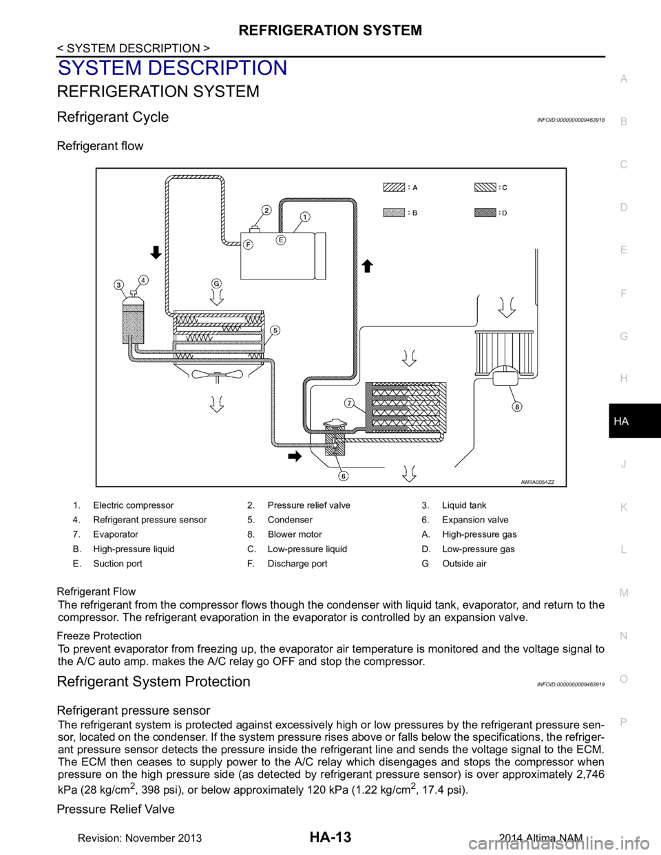
Refrigerant flow
Refrigerant Flow
The refrigerant from the compressor flows though the c ondenser with liquid tank, evaporator, and return to the
compressor. The refrigerant evaporation in the evaporator is controlled by an expansion valve.
Freeze Protection
To prevent evaporator from freezing up, the evaporator air temperature is monitored and the voltage signal to
the A/C auto amp. makes the A/C relay go OFF and stop the compressor.
Refrigerant System ProtectionINFOID:0000000009463919
Refrigerant pressure sensor
The refrigerant system is protected against excessively hi gh or low pressures by the refrigerant pressure sen-
sor, located on the condenser. If the system pressure rise s above or falls below the specifications, the refriger-
ant pressure sensor detects the pressure inside the refrigerant line and sends the voltage signal to the ECM.
The ECM then ceases to supply power to the A/C relay which disengages and stops the compressor when
pressure on the high pressure side (as detected by refr igerant pressure sensor) is over approximately 2,746
kPa (28 kg/cm
2, 398 psi), or below approximately 120 kPa (1.22 kg/cm2, 17.4 psi).
Pressure Relief Valve
1. Electric compressor 2. Pressure relief valve 3. Liquid tank
4. Refrigerant pressure sensor 5. Condenser 6. Expansion valve
7. Evaporator 8. Blower motor A. High-pressure gas
B. High-pressure liquid C. Low-pressure liquid D. Low-pressure gas
E. Suction port F. Discharge port G Outside air
AWIIA0054ZZ
Revision: November 20132014 Altima NAM
Page 2620 of 4801
HA-14
< SYSTEM DESCRIPTION >
REFRIGERATION SYSTEM
The refrigerant system is also protected by a pressure relief valve, located in the rear head of the compressor.
When the pressure of refrigerant in the system increases to an abnormal level [more than 3,727 kPa (38 kg/
cm
2, 540 psi)], the release port on the pressure relief valve automatically opens and releases refrigerant into
the atmosphere.
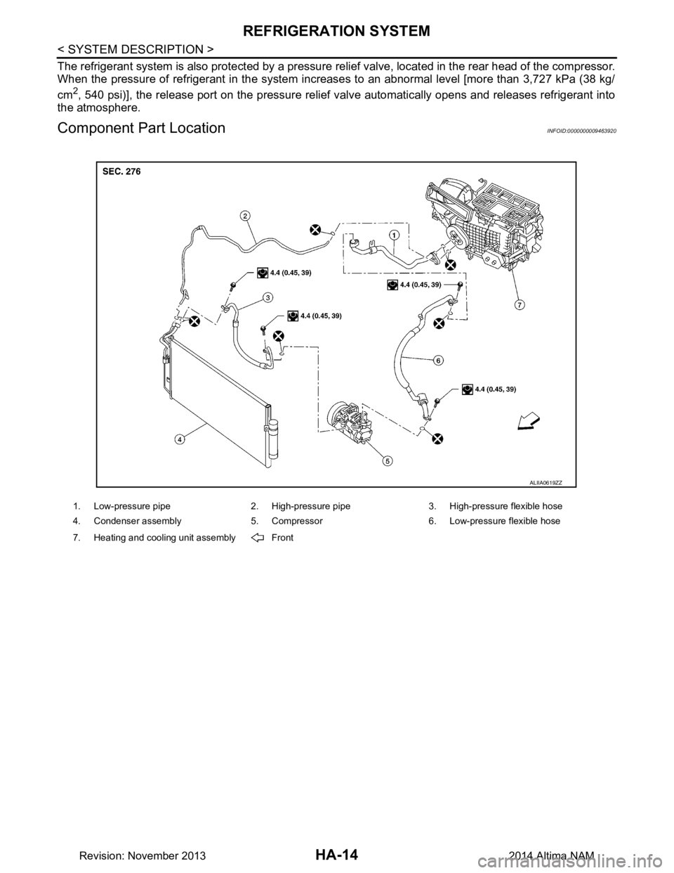
Component Part LocationINFOID:0000000009463920
1. Low-pressure pipe 2. High-pressure pipe 3. High-pressure flexible hose
4. Condenser assembly 5. Compressor 6. Low-pressure flexible hose
7. Heating and cooling unit assembly Front
ALIIA0619ZZ
Revision: November 20132014 Altima NAM
Page 2623 of 4801
HEATER AND AIR CONDITIONING SYSTEM SYMPTOMS
HA-17
< SYMPTOM DIAGNOSIS >
C
D E
F
G H
J
K L
M A
B
HA
N
O P
SYMPTOM DIAGNOSIS
HEATER AND AIR CONDITIONING SYSTEM SYMPTOMS
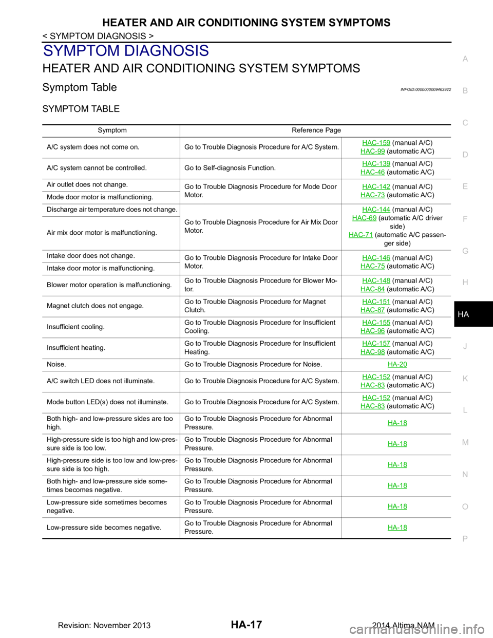
Symptom TableINFOID:0000000009463922
SYMPTOM TABLE
Symptom Reference Page
A/C system does not come on. Go to Trouble Diagnosis Procedure for A/C System. HAC-159
(manual A/C)
HAC-99
(automatic A/C)
A/C system cannot be controlled. Go to Self-diagnosis Function. HAC-139
(manual A/C)
HAC-46
(automatic A/C)
Air outlet does not change. Go to Trouble Diagnosis Procedure for Mode Door
Motor. HAC-142
(manual A/C)
HAC-73
(automatic A/C)
Mode door motor is malfunctioning.
Discharge air temperature does not change.
Go to Trouble Diagnosis Procedure for Air Mix Door
Motor. HAC-144
(manual A/C)
HAC-69
(automatic A/C driver side)
HAC-71
(automatic A/C passen-
ger side)
Air mix door motor is malfunctioning.
Intake door does not change.
Go to Trouble Diagnosis Procedure for Intake Door
Motor. HAC-146
(manual A/C)
HAC-75
(automatic A/C)
Intake door motor is malfunctioning.
Blower motor operation is malfunctioning. Go to Trouble Diagnosis Procedure for Blower Mo-
tor. HAC-148
(manual A/C)
HAC-84
(automatic A/C)
Magnet clutch does not engage. Go to Trouble Diagnosis Procedure for Magnet
Clutch. HAC-151
(manual A/C)
HAC-87
(automatic A/C)
Insufficient cooling. Go to Trouble Diagnosis Procedure for Insufficient
Cooling. HAC-155
(manual A/C)
HAC-96
(automatic A/C)
Insufficient heating. Go to Trouble Diagnosis Procedure for Insufficient
Heating. HAC-157
(manual A/C)
HAC-98
(automatic A/C)
Noise. Go to Trouble Diagnosis Procedure for Noise. HA-20
A/C switch LED does not illuminate. Go to Trouble Diagnosis Procedure for A/C System.HAC-152 (manual A/C)
HAC-83
(automatic A/C)
Mode button LED(s) does not illuminate. Go to Trouble Diagnosis Procedure for A/C System. HAC-152
(manual A/C)
HAC-83
(automatic A/C)
Both high- and low-pressure sides are too
high. Go to Trouble Diagnosis Procedure for Abnormal
Pressure. HA-18
High-pressure side is too high and low-pres-
sure side is too low. Go to Trouble Diagnosis Procedure for Abnormal
Pressure. HA-18
High-pressure side is too low and low-pres-
sure side is too high. Go to Trouble Diagnosis Procedure for Abnormal
Pressure. HA-18
Both high- and low-pressure side some-
times becomes negative. Go to Trouble Diagnosis Procedure for Abnormal
Pressure. HA-18
Low-pressure side sometimes becomes
negative. Go to Trouble Diagnosis Procedure for Abnormal
Pressure. HA-18
Low-pressure side becomes negative.
Go to Trouble Diagnosis Procedure for Abnormal
Pressure. HA-18
Revision: November 20132014 Altima NAM
Page 2624 of 4801
HA-18
< SYMPTOM DIAGNOSIS >
REFRIGERATION SYSTEM SYMPTOMS
REFRIGERATION SYSTEM SYMPTOMS
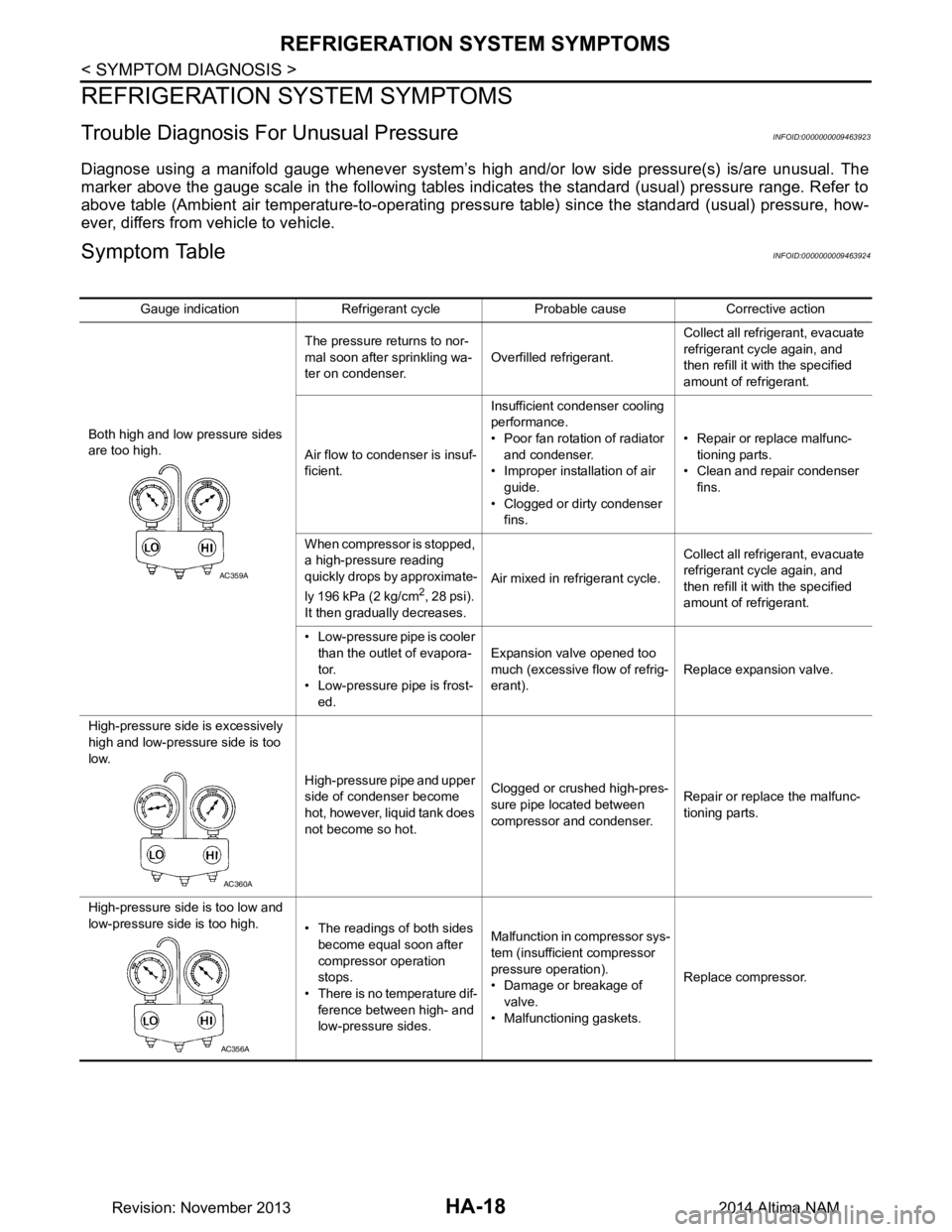
Trouble Diagnosis For Unusual PressureINFOID:0000000009463923
Diagnose using a manifold gauge whenever system’s high and/or low side pressure(s) is/are unusual. The
marker above the gauge scale in the following tables indicates the standard (usual) pressure range. Refer to
above table (Ambient air temperature-to-operating pres sure table) since the standard (usual) pressure, how-
ever, differs from vehicle to vehicle.
Symptom TableINFOID:0000000009463924
Gauge indication Refrigerant cycle Probable cause Corrective action
Both high and low pressure sides
are too high. The pressure returns to nor-
mal soon after sprinkling wa-
ter on condenser. Overfilled refrigerant. Collect all refrigerant, evacuate
refrigerant cycle again, and
then refill it with the specified
amount of refrigerant.
Air flow to condenser is insuf-
ficient. Insufficient condenser cooling
performance.
• Poor fan rotation of radiator and condenser.
• Improper installation of air
guide.
• Clogged or dirty condenser fins. • Repair or replace malfunc-
tioning parts.
• Clean and repair condenser
fins.
When compressor is stopped,
a high-pressure reading
quickly drops by approximate-
ly 196 kPa (2 kg/cm
2, 28 psi).
It then gradually decreases. Air mixed in refrigerant cycle.
Collect all refrigerant, evacuate
refrigerant cycle again, and
then refill it with the specified
amount of refrigerant.
• Low-pressure pipe is cooler than the outlet of evapora-
tor.
• Low-pressure pipe is frost- ed. Expansion valve opened too
much (excessive flow of refrig-
erant). Replace expansion valve.
High-pressure side is excessively
high and low-pressure side is too
low.
High-pressure pipe and upper
side of condenser become
hot, however, liquid tank does
not become so hot. Clogged or crushed high-pres-
sure pipe located between
compressor and condenser. Repair or replace the malfunc-
tioning parts.
High-pressure side is too low and
low-pressure side is too high. • The readings of both sides
become equal soon after
compressor operation
stops.
• There is no temperature dif- ference between high- and
low-pressure sides. Malfunction in compressor sys-
tem (insufficient compressor
pressure operation).
• Damage or breakage of
valve.
• Malfunctioning gaskets. Replace compressor.
AC359A
AC360A
AC356A
Revision: November 20132014 Altima NAM
Page 2625 of 4801
REFRIGERATION SYSTEM SYMPTOMSHA-19
< SYMPTOM DIAGNOSIS >
C
D E
F
G H
J
K L
M A
B
HA
N
O P
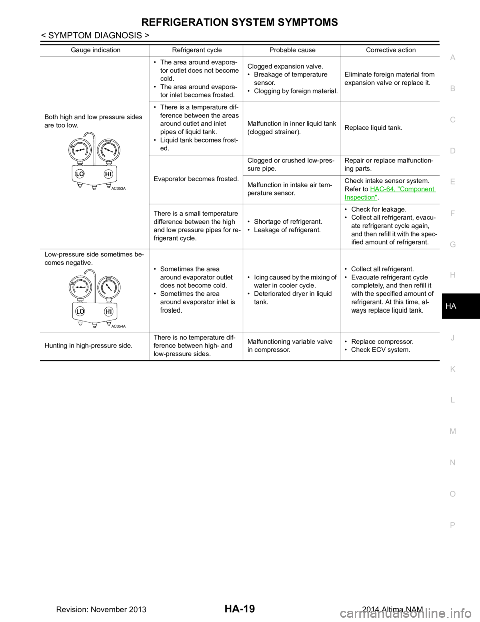
Both high and low pressure sides
are too low. • The area around evapora-
tor outlet does not become
cold.
• The area around evapora- tor inlet becomes frosted. Clogged expansion valve.
• Breakage of temperature sensor.
• Clogging by foreign material. Eliminate foreign material from
expansion valve or replace it.
• There is a temperature dif- ference between the areas
around outlet and inlet
pipes of liquid tank.
• Liquid tank becomes frost- ed. Malfunction in inner liquid tank
(clogged strainer). Replace liquid tank.
Evaporator becomes frosted. Clogged or crushed low-pres-
sure pipe. Repair or replace malfunction-
ing parts.
Malfunction in intake air tem-
perature sensor. Check intake sensor system.
Refer to HAC-64, "Component
Inspection".
There is a small temperature
difference between the high
and low pressure pipes for re-
frigerant cycle. • Shortage of refrigerant.
• Leakage of refrigerant. • Check for leakage.
• Collect all refrigerant, evacu-
ate refrigerant cycle again,
and then refill it with the spec-
ified amount of refrigerant.
Low-pressure side sometimes be-
comes negative. • Sometimes the area
around evaporator outlet
does not become cold.
• Sometimes the area
around evaporator inlet is
frosted. • Icing caused by the mixing of
water in cooler cycle.
• Deteriorated dryer in liquid
tank. • Collect all refrigerant.
• Evacuate refrigerant cycle completely, and then refill it
with the specified amount of
refrigerant. At this time, al-
ways replace liquid tank.
Hunting in high-pressure side. There is no temperature dif-
ference between high- and
low-pressure sides. Malfunctioning variable valve
in compressor. • Replace compressor.
• Check ECV system.
Gauge indication Refrigerant cycle Probable cause Corrective action
AC353A
AC354A
Revision: November 20132014 Altima NAM