2014 NISSAN TEANA check oil
[x] Cancel search: check oilPage 2417 of 4801
PRECAUTIONSEXT-3
< PRECAUTION >
C
D E
F
G H
I
J
L
M A
B
EXT
N
O P
PRECAUTION
PRECAUTIONS
Precaution for Supplemental Restraint System (SRS) "AIR BAG" and "SEAT BELT
PRE-TENSIONER"
INFOID:0000000009951571
The Supplemental Restraint System such as “A IR BAG” and “SEAT BELT PRE-TENSIONER”, used along
with a front seat belt, helps to reduce the risk or severi ty of injury to the driver and front passenger for certain
types of collision. Information necessary to service t he system safely is included in the SR and SB section of
this Service Manual.
WARNING:
• To avoid rendering the SRS inoper ative, which could increase the risk of personal injury or death in
the event of a collision which would result in air bag inflation, all maintenance must be performed by
an authorized NISSAN/INFINITI dealer.
• Improper maintenance, including in correct removal and installation of the SRS, can lead to personal
injury caused by unintentional act ivation of the system. For removal of Spiral Cable and Air Bag
Module, see the SR section.
• Do not use electrical test equipm ent on any circuit related to the SRS unless instructed to in this
Service Manual. SRS wiring harnesses can be identi fied by yellow and/or orange harnesses or har-
ness connectors.
PRECAUTIONS WHEN USING POWER TOOLS (AIR OR ELECTRIC) AND HAMMERS
WARNING:
• When working near the Airbag Diagnosis Sensor Un it or other Airbag System sensors with the Igni-
tion ON or engine running, DO NOT use air or el ectric power tools or strike near the sensor(s) with a
hammer. Heavy vibration could activate the sensor( s) and deploy the air bag(s), possibly causing
serious injury.
• When using air or electric power tools or hammers , always switch the Ignition OFF, disconnect the
battery and wait at least three mi nutes before performing any service.
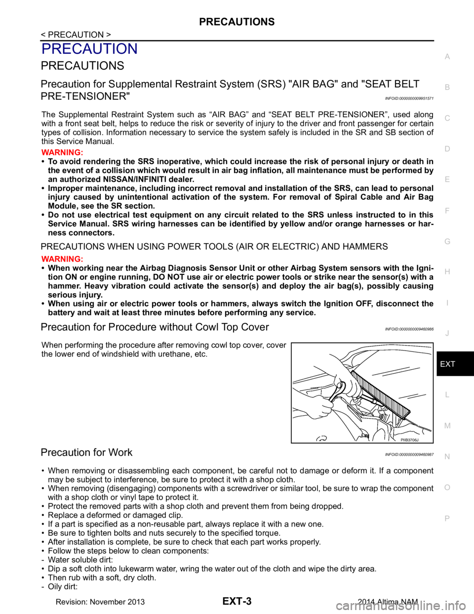
Precaution for Procedure without Cowl Top CoverINFOID:0000000009460986
When performing the procedure after removing cowl top cover, cover
the lower end of windshield with urethane, etc.
Precaution for WorkINFOID:0000000009460987
• When removing or disassembling each component, be ca reful not to damage or deform it. If a component
may be subject to interference, be sure to protect it with a shop cloth.
• When removing (disengaging) components with a screwdriver or similar tool, be sure to wrap the component with a shop cloth or vinyl tape to protect it.
• Protect the removed parts with a shop cloth and prevent them from being dropped.
• Replace a deformed or damaged clip.
• If a part is specified as a non-reusabl e part, always replace it with a new one.
• Be sure to tighten bolts and nuts securely to the specified torque.
• After installation is complete, be sure to check that each part works properly.
• Follow the steps below to clean components:
- Water soluble dirt:
• Dip a soft cloth into lukewarm water, wring the water out of the cloth and wipe the dirty area.
• Then rub with a soft, dry cloth.
-Oily dirt:
PIIB3706J
Revision: November 20132014 Altima NAM
Page 2466 of 4801
FAX-14
< REMOVAL AND INSTALLATION >
FRONT DRIVE SHAFT
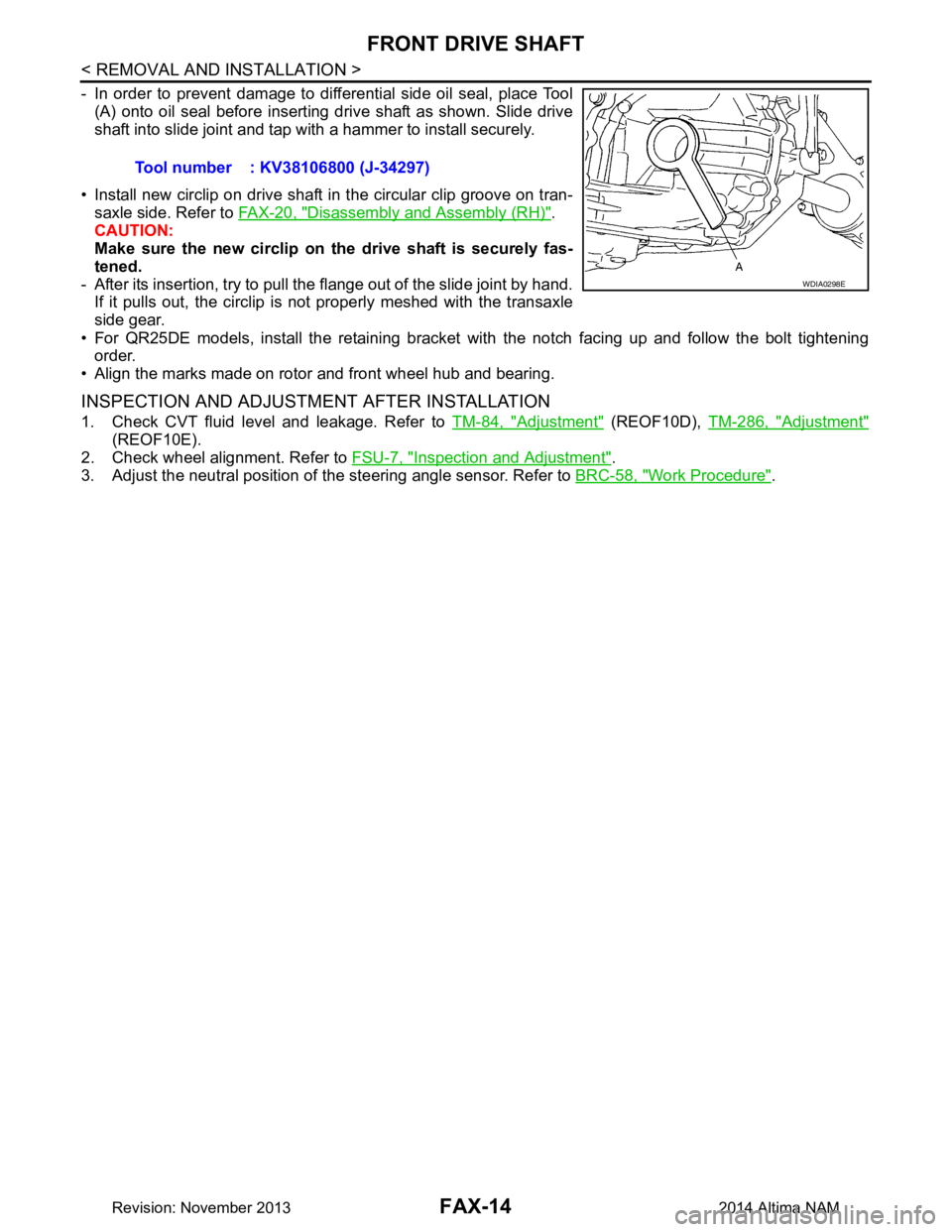
- In order to prevent damage to differential side oil seal, place Tool(A) onto oil seal before inserting drive shaft as shown. Slide drive
shaft into slide joint and tap with a hammer to install securely.
• Install new circlip on drive shaft in the circular clip groove on tran- saxle side. Refer to FAX-20, "Disassembly and Assembly (RH)"
.
CAUTION:
Make sure the new circlip on the drive shaft is securely fas-
tened.
- After its insertion, try to pull the flange out of the slide joint by hand. If it pulls out, the circlip is not properly meshed with the transaxle
side gear.
• For QR25DE models, install the retaining bracket with the notch facing up and follow the bolt tightening
order.
• Align the marks made on rotor and front wheel hub and bearing.
INSPECTION AND ADJUSTMENT AFTER INSTALLATION
1. Check CVT fluid level and leakage. Refer to TM-84, "Adjustment" (REOF10D), TM-286, "Adjustment"
(REOF10E).
2. Check wheel alignment. Refer to FSU-7, "Inspection and Adjustment"
.
3. Adjust the neutral position of the steering angle sensor. Refer to BRC-58, "Work Procedure"
.
Tool number : KV38106800 (J-34297)
WDIA0298E
Revision: November 20132014 Altima NAM
Page 2503 of 4801
FSU-2
< PRECAUTION >
PRECAUTIONS
PRECAUTION
PRECAUTIONS
Precaution for Supplemental Restraint System (SRS) "AIR BAG" and "SEAT BELT
PRE-TENSIONER"
INFOID:0000000009951705
The Supplemental Restraint System such as “A IR BAG” and “SEAT BELT PRE-TENSIONER”, used along
with a front seat belt, helps to reduce the risk or severi ty of injury to the driver and front passenger for certain
types of collision. Information necessary to service the system safely is included in the SR and SB section of
this Service Manual.
WARNING:
• To avoid rendering the SRS inopera tive, which could increase the risk of personal injury or death in
the event of a collision which would result in air bag inflation, all maintenance must be performed by
an authorized NISS AN/INFINITI dealer.
• Improper maintenance, including in correct removal and installation of the SRS, can lead to personal
injury caused by unintent ional activation of the system. For re moval of Spiral Cable and Air Bag
Module, see the SR section.
• Do not use electrical test equipmen t on any circuit related to the SRS unless instructed to in this
Service Manual. SRS wiring harn esses can be identified by yellow and/or orange harnesses or har-
ness connectors.
PRECAUTIONS WHEN USING POWER TOOLS (AIR OR ELECTRIC) AND HAMMERS
WARNING:
• When working near the Airbag Diagnosis Sensor Unit or other Airbag System sensors with the Igni-
tion ON or engine running, DO NOT use air or electri c power tools or strike near the sensor(s) with a
hammer. Heavy vibration could activate the sensor( s) and deploy the air bag(s), possibly causing
serious injury.
• When using air or electric power tools or hammers , always switch the Ignition OFF, disconnect the
battery and wait at least three minutes before performing any service.
General PrecautionsINFOID:0000000009460620
• When installing rubber bushings, the final tightening mu st be carried out under unladen conditions with tires
on ground. Oil might shorten the life of rubber bushings. Be sure to wipe off any spilled oil.
- Unladen conditions mean that fuel, engine coolant and lubricant are full. Spare tire, jack, hand tools and mats are in designated positions.
• After servicing suspension parts, be sure to check wheel alignment.
• Self-lock nuts are not reusable. Always use new ones when installing. Since new self-lock nuts are pre-oiled,
tighten as they are.
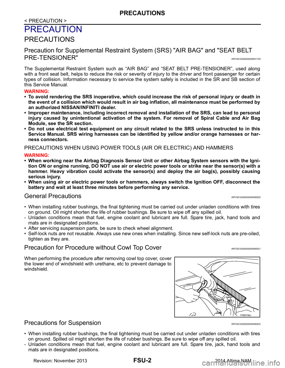
Precaution for Procedure without Cowl Top CoverINFOID:0000000009460621
When performing the procedure after removing cowl top cover, cover
the lower end of windshield with urethane, etc to prevent damage to
windshield.
Precautions for SuspensionINFOID:0000000009460622
• When installing rubber bushings, the final tightening mu st be carried out under unladen conditions with tires
on ground. Spilled oil might shorten the life of rubber bushings. Be sure to wipe off any spilled oil.
- Unladen conditions mean that fuel, engine coolant and lubricant are full. Spare tire, jack, hand tools and mats are in designated positions.
PIIB3706J
Revision: November 20132014 Altima NAM
Page 2504 of 4801
PRECAUTIONSFSU-3
< PRECAUTION >
C
D
F
G H
I
J
K L
M A
B
FSU
N
O P
• After servicing suspension parts, be sure to check wheel alignment.
• Self-lock nuts are not reusable. Always use new ones when installing. Since new self-lock nuts are pre-oiled, tighten as they are.
Revision: November 20132014 Altima NAM
Page 2508 of 4801
FRONT SUSPENSION ASSEMBLYFSU-7
< PERIODIC MAINTENANCE >
C
D
F
G H
I
J
K L
M A
B
FSU
N
O P
PERIODIC MAINTENANCE
FRONT SUSPENSION ASSEMBLY
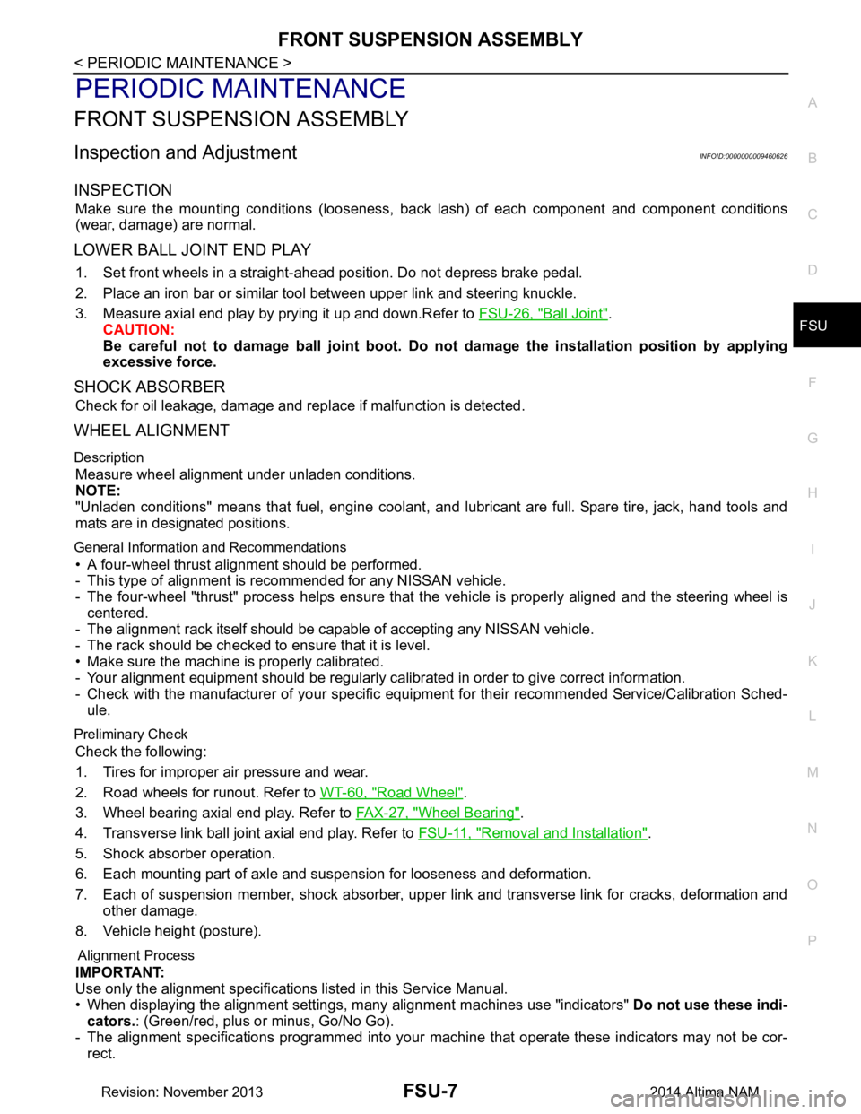
Inspection and AdjustmentINFOID:0000000009460626
INSPECTION
Make sure the mounting conditions (looseness, back lash) of each component and component conditions
(wear, damage) are normal.
LOWER BALL JOINT END PLAY
1. Set front wheels in a straight-ahead position. Do not depress brake pedal.
2. Place an iron bar or similar tool between upper link and steering knuckle.
3. Measure axial end play by prying it up and down.Refer to FSU-26, "Ball Joint"
.
CAUTION:
Be careful not to damage ball joint boot. Do not damage the installation position by applying
excessive force.
SHOCK ABSORBER
Check for oil leakage, damage and repl ace if malfunction is detected.
WHEEL ALIGNMENT
Description
Measure wheel alignment under unladen conditions.
NOTE:
"Unladen conditions" means that fuel, engine coolant, and lubricant are full. Spare tire, jack, hand tools and
mats are in designated positions.
General Information and Recommendations
• A four-wheel thrust alignment should be performed.
- This type of alignment is re commended for any NISSAN vehicle.
- The four-wheel "thrust" process helps ensure that t he vehicle is properly aligned and the steering wheel is
centered.
- The alignment rack itself should be capable of accepting any NISSAN vehicle.
- The rack should be checked to ensure that it is level.
• Make sure the machine is properly calibrated.
- Your alignment equipment should be regularly ca librated in order to give correct information.
- Check with the manufacturer of your specific equi pment for their recommended Service/Calibration Sched-
ule.
Preliminary Check
Check the following:
1. Tires for improper air pressure and wear.
2. Road wheels for runout. Refer to WT-60, "Road Wheel"
.
3. Wheel bearing axial end play. Refer to FAX-27, "Wheel Bearing"
.
4. Transverse link ball joint axial end play. Refer to FSU-11, "Removal and Installation"
.
5. Shock absorber operation.
6. Each mounting part of axle and suspension for looseness and deformation.
7. Each of suspension member, shock absorber, upper link and transverse link for cracks, deformation and other damage.
8. Vehicle height (posture).
Alignment Process
IMPORTANT:
Use only the alignment specificati ons listed in this Service Manual.
• When displaying the alignment settings, m any alignment machines use "indicators" Do not use these indi-
cators. : (Green/red, plus or minus, Go/No Go).
- The alignment specifications programmed into your machine that operate these indicators may not be cor-
rect.
Revision: November 20132014 Altima NAM
Page 2510 of 4801
FRONT COIL SPRING AND STRUTFSU-9
< REMOVAL AND INSTALLATION >
C
D
F
G H
I
J
K L
M A
B
FSU
N
O P
REMOVAL AND INSTALLATION
FRONT COIL SPRING AND STRUT
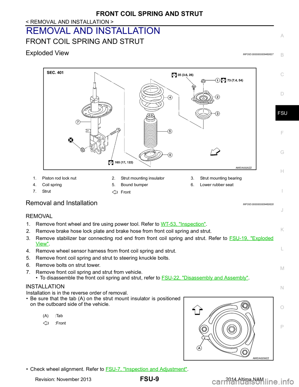
Exploded ViewINFOID:0000000009460627
Removal and InstallationINFOID:0000000009460628
REMOVAL
1. Remove front wheel and tire using power tool. Refer to WT-53, "Inspection".
2. Remove brake hose lock plate and brake hose from front coil spring and strut.
3. Remove stabilizer bar connecting rod end from front coil spring and strut. Refer to FSU-19, "Exploded
View".
4. Remove wheel sensor harness from front coil spring and strut.
5. Remove front coil spring and strut to steering knuckle bolts.
6. Remove bolts on strut tower.
7. Remove front coil spring and strut from vehicle. • To disassemble the front coil spring and strut, refer to FSU-22, "Disassembly and Assembly"
.
INSTALLATION
Installation is in the reverse order of removal.
• Be sure that the tab (A) on the strut mount insulator is positioned on the outboard side of the vehicle.
• Check wheel alignment. Refer to FSU-7, "Inspection and Adjustment"
.
1. Piston rod lock nut 2. Strut mounting insulator 3. Strut mounting bearing
4. Coil spring 5. Bound bumper 6. Lower rubber seat
7. Strut Front
AWEIA0325ZZ
(A) :Tab
:Front
AWEIA0259ZZ
Revision: November 20132014 Altima NAM
Page 2529 of 4801
GI-1
GENERAL INFORMATION
C
D E
F
G H
I
J
K L
M B
GI
SECTION GI
N
O P
CONTENTS
GENERAL INFORMATION
HOW TO USE THIS MANU AL ......................3
HOW TO USE THIS MANUAL ....................... .....3
Description .......................................................... ......3
Terms ........................................................................3
Units ..........................................................................3
Contents ....................................................................3
Relation between Illustrations and Descriptions .......4
Components ..............................................................4
HOW TO FOLLOW TROUBLE DIAGNOSES .....6
Description ................................................................6
How to Follow Test Groups in Trouble Diagnosis ......6
Key to Symbols Signifying Measurements or Pro-
cedures ............................................................... ......
7
HOW TO READ WIRING DIAGRAMS ................9
Connector symbols ............................................. ......9
Sample/wiring diagram -example- ...........................10
Description ..............................................................11
ABBREVIATIONS .......................................... ....13
Abbreviation List .................................................. ....13
TIGHTENING TORQUE OF STANDARD
BOLTS ............................................................ ....
18
Description .......................................................... ....18
Tightening Torque Table (New Standard Includ-
ed) ....................................................................... ....
18
RECOMMENDED CHEMICAL PRODUCTS
AND SEALANTS ............................................ ....
21
Recommended Chemical Products and Sealants ....21
VEHICLE INFORMATION ............................22
IDENTIFICATION INFORMATION ................. ....22
Model Variation ................................................... ....22
Identification Number ..............................................23
Identification Plate ...................................................24
Engine Serial Number .............................................24
CVT Number ...........................................................25
Dimensions .......................................................... ....25
Wheels & Tires ........................................................25
PRECAUTION ..............................................26
PRECAUTIONS .................................................26
Description ........................................................... ....26
Precaution for Supplemental Restraint System
(SRS) "AIR BAG" and "SEAT BELT PRE-TEN-
SIONER" ............................................................. ....
26
Precautions For Xenon Headlamp Service .............26
Procedures without Cowl Top Cover .......................27
Cautions in Removing Battery Terminal and AV
Control Unit .......................................................... ....
27
General Precautions ................................................27
Three Way Catalyst .................................................29
Fuel (Regular Unleaded Gasoline Recommend-
ed) QR25DE ........................................................ ....
29
Fuel (Regular Unleaded Gasoline Recommend-
ed) VQ35DE ........................................................ ....
29
Multiport Fuel Injection System or Engine Control
System ................................................................. ....
29
Hoses ......................................................................29
Engine Oils ..............................................................30
Air Conditioning .......................................................31
LIFTING POINT .................................................32
Special Service Tool ................................................32
Pantograph Jack ......................................................32
Garage Jack and Safety Stand ................................33
2-Pole Lift ................................................................34
Board-on Lift ............................................................35
TOW TRUCK TOWING .....................................36
Tow Truck Towing ...................................................36
Vehicle Recovery (Freeing a Stuck Vehicle) ...........36
WIRING DIAGRAM ......................................38
CONSULT CHECKING SYSTEM .....................38
Wiring Diagram .................................................... ....38
Revision: November 20132014 Altima NAMRevision: November 20132014 Altima NAM
Page 2556 of 4801
GI-28
< PRECAUTION >
PRECAUTIONS
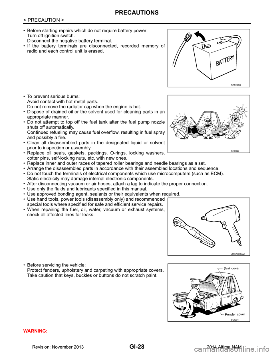
• Before starting repairs which do not require battery power:Turn off ignition switch.
Disconnect the negative battery terminal.
• If the battery terminals are disconnected, recorded memory of
radio and each control unit is erased.
• To prevent serious burns: Avoid contact with hot metal parts.
Do not remove the radiator cap when the engine is hot.
• Dispose of drained oil or the solvent used for cleaning parts in an
appropriate manner.
• Do not attempt to top off the fuel tank after the fuel pump nozzle
shuts off automatically.
Continued refueling may cause fuel overflow, resulting in fuel spray
and possibly a fire.
• Clean all disassembled parts in the designated liquid or solvent
prior to inspection or assembly.
• Replace oil seals, gaskets, packings, O-rings, locking washers, cotter pins, self-locking nuts, etc. with new ones.
• Replace inner and outer races of tapered roller bearings and needle bearings as a set.
• Arrange the disassembled parts in accordance with their assembled locations and sequence.
• Do not touch the terminals of electrical com ponents which use microcomputers (such as ECM).
Static electricity may damage internal electronic components.
• After disconnecting vacuum or air hoses, atta ch a tag to indicate the proper connection.
• Use only the fluids and lubricants specified in this manual.
• Use approved bonding agent, sealants or their equivalents when required.
• Use hand tools, power tools (disassembly only) and recommended special tools where specified for safe and efficient service repairs.
• When repairing the fuel, oil, water, vacuum or exhaust systems,
check all affected lines for leaks.
• Before servicing the vehicle: Protect fenders, upholstery and carpeting with appropriate covers.
Take caution that keys, buckles or buttons do not scratch paint.
WARNING:
SEF289H
SGI233
JPAIA0335ZZ
SGI234
Revision: November 20132014 Altima NAMRevision: November 20132014 Altima NAM