2014 NISSAN TEANA check oil
[x] Cancel search: check oilPage 2252 of 4801
![NISSAN TEANA 2014 Service Manual
EM-254
< SERVICE DATA AND SPECIFICATIONS (SDS) [VQ35DE]
SERVICE DATA AND SPECIFICATIONS (SDS)
PISTON PIN
Unit: mm (in)
*: Always check with the Parts Department for the latest parts information.
CONN NISSAN TEANA 2014 Service Manual
EM-254
< SERVICE DATA AND SPECIFICATIONS (SDS) [VQ35DE]
SERVICE DATA AND SPECIFICATIONS (SDS)
PISTON PIN
Unit: mm (in)
*: Always check with the Parts Department for the latest parts information.
CONN](/manual-img/5/57390/w960_57390-2251.png)
EM-254
< SERVICE DATA AND SPECIFICATIONS (SDS) [VQ35DE]
SERVICE DATA AND SPECIFICATIONS (SDS)
PISTON PIN
Unit: mm (in)
*: Always check with the Parts Department for the latest parts information.
CONNECTING ROD
Unit: mm (in)
1: Always check with the Parts Department for the latest parts information.
2: After installing in connecting rod
CRANKSHAFT
Unit: mm (in)
End gapTop 0.23 - 0.28 (0.0091 - 0.0110) 0.54 (0.0213)
2nd 0.33 - 0.43 (0.0130 - 0.0169) 0.80 (0.0315)
Oil (rail ring) 0.20 - 0.45 (0.0079 - 0.0177) 0.95 (0.0374)
Items Grade* Standard Limit
Piston pin outer diameter Grade No. 0 21.989 - 21.995 (0.8657 - 0.8659) —
Grade No. 1 21.995 - 22.001 (0.8659 - 0.8662) —
Piston to piston pin oil clearance 0.002 - 0.006 (0.0001 - 0.0002) —
Connecting rod bushing oil clearance 0.005 - 0.017 (0.0002 - 0.0007) 0.030 (0.0012)
Items Grade1Standard Limit
Center distance 144.13 - 144.27 (5.6744 - 5.6799) —
Bend [per 100 (3.94)] — 0.15 (0.0059)
Torsion [per 100 (3.94)] — 0.30 (0.0118)
Connecting rod small end inner diameter 23.980 - 24.000 (0.9441 - (0.9449)
Connecting rod bushing inner diameter
2Grade No. 0 22.000 - 22.006 (0.8661 - 0.8664) —
Grade No. 1 22.006 - 22.012 (0.8664 - 0.8666) —
Connecting rod big end diameter (Without bearing) 55.000 - 55.013 (2.1654 - 2.1659) —
Side clearance 0.20 - 0.30 (0.0079 - 0.0118) 0.40 (0.0157)
SEM645SBIA0535E
Revision: November 20132014 Altima NAM
Page 2254 of 4801
![NISSAN TEANA 2014 Service Manual
EM-256
< SERVICE DATA AND SPECIFICATIONS (SDS) [VQ35DE]
SERVICE DATA AND SPECIFICATIONS (SDS)
*: Always check with the Parts Department for the latest parts information.
UNDERSIZE
Unit: mm (in)
MAIN NISSAN TEANA 2014 Service Manual
EM-256
< SERVICE DATA AND SPECIFICATIONS (SDS) [VQ35DE]
SERVICE DATA AND SPECIFICATIONS (SDS)
*: Always check with the Parts Department for the latest parts information.
UNDERSIZE
Unit: mm (in)
MAIN](/manual-img/5/57390/w960_57390-2253.png)
EM-256
< SERVICE DATA AND SPECIFICATIONS (SDS) [VQ35DE]
SERVICE DATA AND SPECIFICATIONS (SDS)
*: Always check with the Parts Department for the latest parts information.
UNDERSIZE
Unit: mm (in)
MAIN BEARING OIL CLEARANCE
Unit: mm (in)
*: Actual clearance
Connecting Rod BearingINFOID:0000000009460593
CONNECTING ROD BEARING
Unit: mm (in)
*: Always check with the Parts Department for the latest parts information.
UNDERSIZE
Unit: mm (in)
0 2.000 - 2.003 (0.0787 - 0.0789)
19.9 - 20.1
(0.783 - 0.791) Black
Grade is the same
for upper and lower
bearings.
1 2.003 - 2.006 (0.0789 - 0.0790) Brown
2 2.006 - 2.009 (0.0790 - 0.0791) Green
3 2.009 - 2.012 (0.0791 - 0.0792) Yellow
4 2.012 - 2.015 (0.0792 - 0.0793) Blue
5 2.015 - 2.018 (0.0793 - 0.0794) Pink
6 2.018 - 2.021 (0.0794 - 0.0796) Purple
7 2.021 - 2.024 (0.0796 - 0.0797) White
01 UPR 2.003 - 2.006 (0.0789 - 0.0790) Brown
Grade and color are
different for upper
and lower bearings.
LWR 2.000 - 2.003 (0.0787 - 0.0789) Black
12 UPR 2.006 - 2.009 (0.0790 - 0.0791) Green
LWR 2.003 - 2.006 (0.0789 - 0.0790) Brown
23 UPR 2.009 - 2.012 (0.0791 - 0.0792) Yellow
LWR 2.006 - 2.009 (0.0790 - 0.0791) Green
34 UPR 2.012 - 2.015 (0.0792 - 0.0793) Blue
LWR 2.009 - 2.012 (0.0791 - 0.0792) Yellow
45 UPR 2.015 - 2.018 (0.0793 - 0.0794) Pink
LWR 2.012 - 2.015 (0.0792 - 0.0793) Blue
56 UPR 2.018 - 2.021 (0.0794 - 0.0796) Purple
LWR 2.015 - 2.018 (0.0793 - 0.0794) Pink
67 UPR 2.021 - 2.024 (0.0796 - 0.0797) White
LWR 2.018 - 2.021 (0.0794 - 0.0796) Purple
Items Thickness Main journal diameter
0.25 (0.0098) 2.132 - 2.140 (0.0839 - 0.0843) Grind so that bearing clearance is the specified value.
Items Standard Limit
Main bearing oil clearance 0.012 - 0.022 (0.0005 - 0.0009)* 0.065 (0.0026)
Grade number* Thickness Identification color (mark) 0 1.500 - 1.503 (0.0591 - 0.0592) Black
1 1.503 - 1.506 (0.0592 - 0.0593) Brown
2 1.506 - 1.509 (0.0593 - 0.0594) Green
Items Thickness Crank pin journal diameter (Dp)
0.25 (0.0098) 1.626 - 1.634 (0.0640 - 0.0643) Grind so that bearing clearance is the specified value.
Revision: November 20132014 Altima NAM
Page 2270 of 4801

EXL-4
< PRECAUTION >
PRECAUTIONS
PRECAUTION
PRECAUTIONS
Precaution for Supplemental Restraint System (SRS) "AIR BAG" and "SEAT BELT
PRE-TENSIONER"
INFOID:0000000009951582
The Supplemental Restraint System such as “A IR BAG” and “SEAT BELT PRE-TENSIONER”, used along
with a front seat belt, helps to reduce the risk or severi ty of injury to the driver and front passenger for certain
types of collision. Information necessary to service the system safely is included in the SR and SB section of
this Service Manual.
WARNING:
• To avoid rendering the SRS inopera tive, which could increase the risk of personal injury or death in
the event of a collision which would result in air bag inflation, all maintenance must be performed by
an authorized NISS AN/INFINITI dealer.
• Improper maintenance, including in correct removal and installation of the SRS, can lead to personal
injury caused by unintent ional activation of the system. For re moval of Spiral Cable and Air Bag
Module, see the SR section.
• Do not use electrical test equipmen t on any circuit related to the SRS unless instructed to in this
Service Manual. SRS wiring harn esses can be identified by yellow and/or orange harnesses or har-
ness connectors.
PRECAUTIONS WHEN USING POWER TOOLS (AIR OR ELECTRIC) AND HAMMERS
WARNING:
• When working near the Airbag Diagnosis Sensor Unit or other Airbag System sensors with the Igni-
tion ON or engine running, DO NOT use air or electri c power tools or strike near the sensor(s) with a
hammer. Heavy vibration could activate the sensor( s) and deploy the air bag(s), possibly causing
serious injury.
• When using air or electric power tools or hammers , always switch the Ignition OFF, disconnect the
battery and wait at least three minutes before performing any service.
General precautions fo r service operationsINFOID:0000000009463538
• Do not work with wet hands.
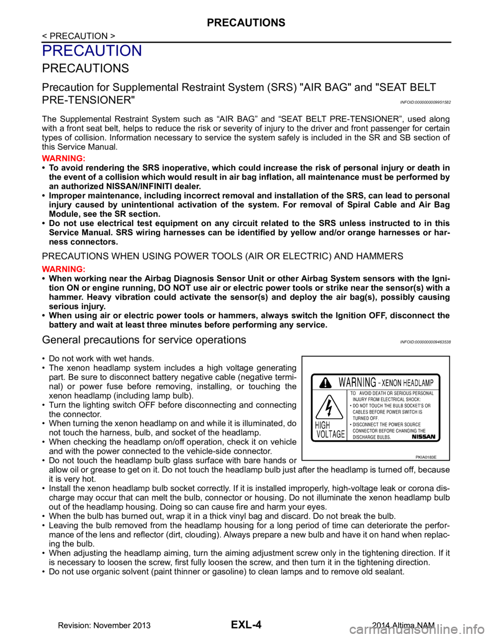
• The xenon headlamp system includes a high voltage generating
part. Be sure to disconnect batte ry negative cable (negative termi-
nal) or power fuse before removing, installing, or touching the
xenon headlamp (including lamp bulb).
• Turn the lighting switch OFF before disconnecting and connecting the connector.
• When turning the xenon headlamp on and while it is illuminated, do
not touch the harness, bulb, and socket of the headlamp.
• When checking the headlamp on/off operation, check it on vehicle and with the power connected to the vehicle-side connector.
• Do not touch the headlamp bulb glass surface with bare hands or allow oil or grease to get on it. Do not touch the headl amp bulb just after the headlamp is turned off, because
it is very hot.
• Install the xenon headlamp bulb socket co rrectly. If it is installed improperly, high-voltage leak or corona dis-
charge may occur that can melt the bulb, connector or housing. Do not illuminate the xenon headlamp bulb
out of the headlamp housing. Doing so can cause fire and harm your eyes.
• When the bulb has burned out, wrap it in a thick vinyl bag and discard. Do not break the bulb.
• Leaving the bulb removed from the headlamp housing for a long period of time can deteriorate the perfor- mance of the lens and reflector (dirt, clouding). Al ways prepare a new bulb and have it on hand when replac-
ing the bulb.
• When adjusting the headlamp aiming, turn the aiming adjus tment screw only in the tightening direction. If it
is necessary to loosen the screw, first fully loosen the screw, and then turn it in the tightening direction.
• Do not use organic solvent (paint thinner or gasoline) to clean lamps and to remove old sealant.
PKIA0183E
Revision: November 20132014 Altima NAMRevision: November 20132014 Altima NAM
Page 2271 of 4801

PRECAUTIONSEXL-5
< PRECAUTION >
C
D E
F
G H
I
J
K
M A
B
EXL
N
O P
Precaution for WorkINFOID:0000000009463539
• When removing or disassembling each component, be ca reful not to damage or deform it. If a component
may be subject to interference, be sure to protect it with a shop cloth.
• When removing (disengaging) components with a screwdriver or similar tool, be sure to wrap the component
with a shop cloth or vinyl tape to protect it.
• Protect the removed parts with a shop cloth and prevent them from being dropped.
• Replace a deformed or damaged clip.
• If a part is specified as a non-reusabl e part, always replace it with a new one.
• Be sure to tighten bolts and nuts securely to the specified torque.
• After installation is complete, be sure to check that each part works properly.
• Follow the steps below to clean components:
- Water soluble dirt:
• Dip a soft cloth into lukewarm water, wring the water out of the cloth and wipe the dirty area.
• Then rub with a soft, dry cloth.
-Oily dirt:
• Dip a soft cloth into lukewarm water with mild detergent (concentration: within 2 to 3%) and wipe the dirty
area.
• Then dip a cloth into fresh water, wring the water out of the cloth and wipe the detergent off.
• Then rub with a soft, dry cloth.
- Do not use organic solvent such as thinner, benzene, alcohol or gasoline.
- For genuine leather seats, use a genuine leather seat cleaner.
Revision: November 20132014 Altima NAMRevision: November 20132014 Altima NAM
Page 2364 of 4801

EXL-98
< DTC/CIRCUIT DIAGNOSIS >
DAYTIME LIGHT RELAY CIRCUIT
DAYTIME LIGHT RELAY CIRCUIT
DescriptionINFOID:0000000009463588
The BCM sends a daytime light request to the IPDM E/R via the CAN communication lines. The power flows
through fuse 43 located in IPDM E/R to the daytime li ght relay coil. When the IPDM E/R operates the daytime
light relay, power is sent to the daytime lamps.
Diagnosis ProcedureINFOID:0000000009463589
Regarding Wiring Diagram information, refer to EXL-39, "Wiring Diagram".
1.CHECK DAYTIME LIGHT RELAY VOLTAGE SUPPLY
1. Turn the ignition switch OFF.
2. Remove the daytime light relay.
3. Check the voltage between the daytime light relay harness connector E228 and ground.
Is the inspection result normal?
YES >> GO TO 3.
NO >> GO TO 2.
2.CHECK DAYTIME LIGHT RELAY CIRCUIT
1. Turn the ignition switch OFF.
2. Disconnect IPDM E/R harness connector E18.
3. Check continuity between the IPDM E/R harness c onnector E18 and the daytime light relay harness con-
nector E228.
4. Check continuity between the IP DM E/R harness connector E18 and ground.
Is the inspection result normal?
YES >> Replace IPDM E/R. Refer to PCS-32, "Removal and Installation".
NO >> Repair or replace the harness or connector.
3.CHECK DAYTIME LIGHT RELAY CONTROL CIRCUIT
1. Turn the ignition switch OFF.
2. Check continuity between the IPDM E/R harness connector E201 and the daytime light relay harness
connector E228.
Daytime light relay (− )Voltage
Connector Terminal
E228 2
Ground Battery voltage
5
Daytime light relay IPDM E/R Continuity
Connector Terminal Connector Terminal
E228 2
E18 14 Ye s
5
Connector Terminal — Continuity
E18 14 Ground No
Daytime light relay IPDM E/R Continuity
Connector Terminal Connector Terminal
E228 1 E201 85 Yes
Revision: November 20132014 Altima NAMRevision: November 20132014 Altima NAM
Page 2388 of 4801

EXL-122
< PERIODIC MAINTENANCE >
HEADLAMP
PERIODIC MAINTENANCE
HEADLAMP
Aiming AdjustmentINFOID:0000000009463617
PREPARATION BEFORE ADJUSTING
Before performing aiming adjustment, check the following:
• Ensure all tires are inflated to correct pressure.
• Place vehicle and screen on level surface.
• Ensure there is no load in vehicle other than the driver (or equivalent weight placed in driver's position).
• Coolant and engine oil filled to correct level, and fuel tank full.
• Remove cargo and/or luggage to maintain an unloaded vehicle condition.
• Confirm spare tire, jack and tools are properly stowed.
• Carefully wipe off any dirt from headlamp lens. CAUTION:
Do not use organic solvent (thinner, gasoline etc.)
• Place a driver or equivalent weight of 68.5 kg (150 lb) on the driver seat.
• By hand, bounce the front and rear of the vehicle to settle the suspension and eliminate any static load.
• Place the front tires in the straight ahead position.
• Aim each headlamp individually and ensure other headlamp beam pattern is blocked from screen.
NOTE:
• For headlamp aiming details, refer to regulations in your area.
• By regulation, no means for horizontal aim adjustment is provided from the factory; only vertical aim is
adjustable.
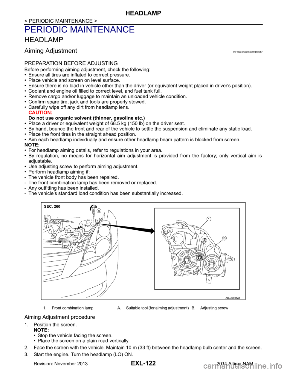
• Use adjusting screw to perform aiming adjustment.
• Perform headlamp aiming if:
- The vehicle front body has been repaired.
- The front combination lamp has been removed or replaced.
- Any outfitting has been installed.
- The vehicle’s standard load condition has been substantially increased.
Aiming Adjustment procedure
1. Position the screen.
NOTE:
• Stop the vehicle facing the screen.
• Place the screen on a plain road vertically.
2. Face the screen with the vehicle. Maintain 10 m (33 ft) between the headlamp bulb center and the screen.
3. Start the engine. Turn the headlamp (LO) ON.
1. Front combination lamp A. Suitable tool (for aiming adjustment) B. Adjusting screw
ALLIA0034ZZ
Revision: November 20132014 Altima NAMRevision: November 20132014 Altima NAM
Page 2390 of 4801

EXL-124
< PERIODIC MAINTENANCE >
FRONT FOG LAMP
FRONT FOG LAMP
Aiming AdjustmentINFOID:0000000009463618
PREPARATION BEFORE ADJUSTING
The fog lamp is a semi-sealed beam type which uses a replaceable halogen bulb. Before performing aiming
adjustment procedure, check the following:
• Ensure all tires are inflated to correct pressure.
• Place vehicle and screen on level surface.
• Ensure there is no load in vehicle other than the driver (or equivalent weight placed in driver's position).
• Coolant and engine oil filled to correct level, and fuel tank full.
• Remove cargo and/or luggage to maintain an unloaded vehicle condition.
• Confirm spare tire, jack and tools are properly stowed.
• Carefully wipe off any dirt from headlamp lens. CAUTION:
Do not use organic solvent (thinner, gasoline etc.)
• Place a driver or equivalent weight of 68.5 kg (150 lb) on the driver seat.
• By hand, bounce the front and rear of the vehicle to settle the suspension and eliminate any static load.
• Place the front tires in the straight ahead position.
• Aim each headlamp individually and ensure other headlamp beam pattern is blocked from screen.
NOTE:
• For headlamp aiming details, refer to regulations in your area.
• By regulation, no means for horizontal aim adjustment is provided from the factory; only vertical aim is
adjustable.
• Use adjusting screw to perform aiming adjustment.
• Perform headlamp aiming if:
- The vehicle front body has been repaired.
- The front combination lamp has been removed or replaced.
- Any outfitting has been installed.
- The vehicle’s standard load condition has been substantially increased.
Aiming Adjustment Procedure
1. Place the screen. NOTE:
• Stop the vehicle facing the wall.
• Place the board on a plain road vertically.
2. Face the vehicle with the screen. Maintain 7.62 m (25.0 ft) between the front fog lamp center and the
screen.
3. Start the engine. Turn the front fog lamp ON. NOTE:
Shut off the headlamp light with the board to prevent from illuminating the adjustment screen.
CAUTION:
Do not cover the lens surface with a tape etc. The lens is made of resin.
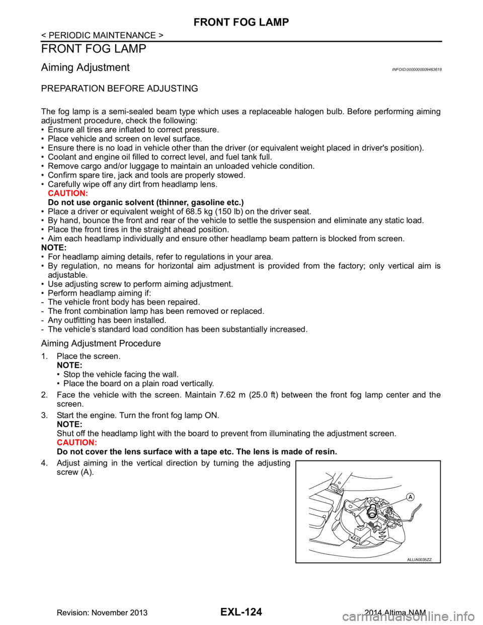
4. Adjust aiming in the vertical direction by turning the adjusting screw (A).
ALLIA0035ZZ
Revision: November 20132014 Altima NAMRevision: November 20132014 Altima NAM
Page 2414 of 4801

EXL-148
< SERVICE DATA AND SPECIFICATIONS (SDS)
SERVICE DATA AND SPECIFICATIONS (SDS)
SERVICE DATA AND SPECIFICATIONS (SDS)
SERVICE DATA AND SPECIFICATIONS (SDS)
Bulb SpecificationsINFOID:0000000009463650
*: Always check with the Parts Department for the latest parts information.Item Wattage (W)*
Front combination lamp Low beam (halogen) 55
Low beam (xenon) 35
High beam 65
Side marker lamp 5
Turn signal/Park lamp 28/8 (amber)
Door mirror side turn signal lamp (if equipped) LED
Rear combination lamp St op /Ta il la mp
21/5
LED
Turn signal lamp 27
Back-up lamp 16
Side marker lamp 5
Fog lamp (if equipped) 55
Daytime running lamp built-in fog lamp (Canada only) 19
License plate lamp 5
High-mounted stop lamp Parcel shelf mounted LED
Rear spoiler mounted LED
Revision: November 20132014 Altima NAMRevision: November 20132014 Altima NAM