2014 NISSAN TEANA check oil
[x] Cancel search: check oilPage 2632 of 4801
HA-26
< PERIODIC MAINTENANCE >
OIL
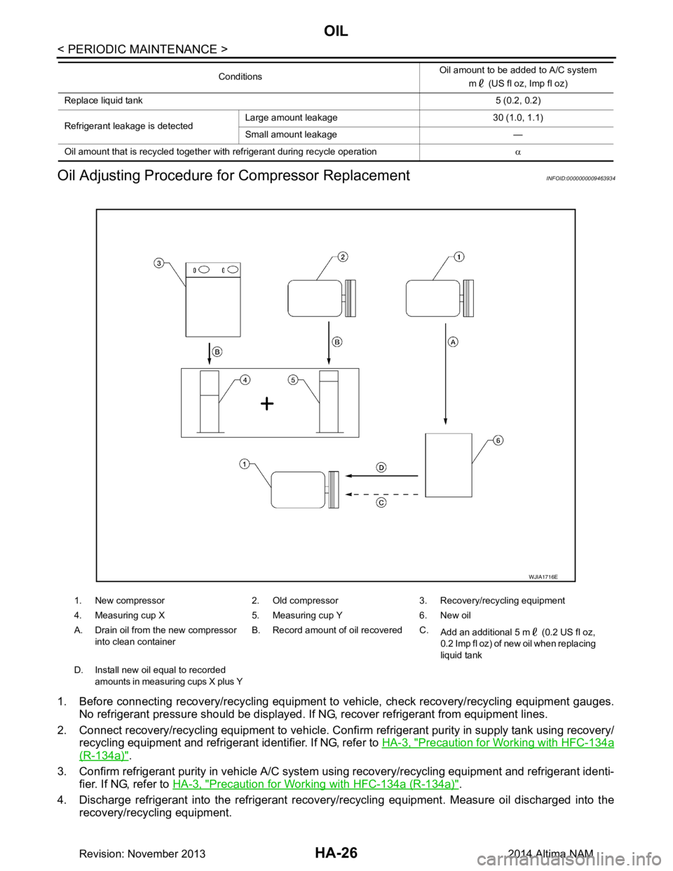
Oil Adjusting Procedure fo r Compressor Replacement
INFOID:0000000009463934
1. Before connecting recovery/recycling equipment to vehicle, check recovery/recycling equipment gauges.
No refrigerant pressure should be displayed. If NG, recover refrigerant from equipment lines.
2. Connect recovery/recycling equipment to vehicle. Confi rm refrigerant purity in supply tank using recovery/
recycling equipment and refrigerant identifier. If NG, refer to HA-3, "Precaution for Working with HFC-134a
(R-134a)".
3. Confirm refrigerant purity in vehi cle A/C system using recovery/recycling equipment and refrigerant identi-
fier. If NG, refer to HA-3, "Precaution for Working with HFC-134a (R-134a)"
.
4. Discharge refrigerant into the refrigerant recove ry/recycling equipment. Measure oil discharged into the
recovery/recycling equipment.
Replace liquid tank 5 (0.2, 0.2)
Refrigerant leakage is detected Large amount leakage 30 (1.0, 1.1)
Small amount leakage —
Oil amount that is recycled together with refrigerant during recycle operation α
Conditions
Oil amount to be added to A/C system
m (US fl oz, Imp fl oz)
1. New compressor 2. Old compressor 3. Recovery/recycling equipment
4. Measuring cup X 5. Measuring cup Y 6. New oil
A. Drain oil from the new compressor into clean container B. Record amount of oil recovered C.
Add an additional 5 m (0.2 US fl oz,
0.2 Imp fl oz) of new oil when replacing
liquid tank
D. Install new oil equal to recorded amounts in measuring cups X plus Y
WJIA1716E
Revision: November 20132014 Altima NAM
Page 2637 of 4801
COMPRESSORHA-31
< REMOVAL AND INSTALLATION >
C
D E
F
G H
J
K L
M A
B
HA
N
O P
4. Remove the drive belt. Refer to EM-19, "Removal and Installation" (QR25DE), or EM-134, "Removal and
Installation" (VQ35DE).
5. Reposition the power steering line. Refer to ST-40, "Exploded View"
.
6. Disconnect the A/C pipes from the compressor. CAUTION:
Cap or wrap the joint of the A/C pipes with suitable material such as vinyl tape to avoid the entry of
air.
7. Disconnect the harness connector from the compressor.
8. Remove the compressor bolts and the compressor.
INSTALLATION
Installation is in the reverse order of removal.
CAUTION:
• Do not reuse the O-rings.
• Apply A/C compressor oil to th e new O-rings for installation.
• After charging the A/C refriger ant, check for leaks. Refer to HA-21, "Leak Test"
.
• Tighten the compressor bolts to specification. Refer to HA-30, "COMPRESSOR : Exploded View"
.
MAGNET CLUTCH
MAGNET CLUTCH : Removal and InstallationINFOID:0000000009463938
REMOVAL
1. Remove the front under cover. Refer to EXT-28, "Removal and Installation".
2. Partially remove the fender protector (RH). Refer to EXT-26, "FENDER PROTECTOR : Removal and
Installation".
3. Remove the drive belt. Refer to EM-19, "Removal and Installation"
(QR25DE), or EM-134, "Removal and
Installation" (VQ35DE).
4. Remove the center bolt by holding the clutch disc steady using a suitable tool.
5. Remove the clutch disc and shims. CAUTION:
Retain all the shim s for installation.
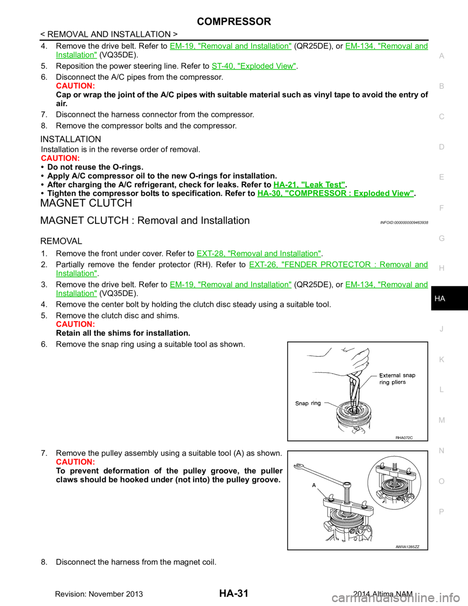
6. Remove the snap ring using a suitable tool as shown.
7. Remove the pulley assembly using a suitable tool (A) as shown. CAUTION:
To prevent deformation of th e pulley groove, the puller
claws should be hooked under (not into) the pulley groove.
8. Disconnect the harness from the magnet coil.
RHA072C
AWIIA1285ZZ
Revision: November 20132014 Altima NAM
Page 2638 of 4801
HA-32
< REMOVAL AND INSTALLATION >
COMPRESSOR
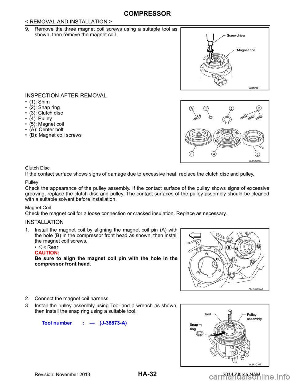
9. Remove the three magnet coil screws using a suitable tool asshown, then remove the magnet coil.
INSPECTION AFTER REMOVAL
•(1): Shim
• (2): Snap ring
• (3): Clutch disc
• (4): Pulley
• (5): Magnet coil
• (A): Center bolt
• (B): Magnet coil screws
Clutch Disc
If the contact surface shows signs of damage due to excessive heat, replace the clutch disc and pulley.
Pulley
Check the appearance of the pulley assembly. If the cont act surface of the pulley shows signs of excessive
grooving, replace the clutch disc and pulley. The contact surfaces of the pulley assembly should be cleaned
with a suitable solvent before installation.
Magnet Coil
Check the magnet coil for a loose connection or cracked insulation. Replace as necessary.
INSTALLATION
1. Install the magnet coil by aligning the magnet coil pin (A) with
the hole (B) in the compressor front head as shown, then install
the magnet coil screws.
• : Rear
CAUTION:
Be sure to align the magnet coil pin with the hole in the
compressor front head.
2. Connect the magnet coil harness.
3. Install the pulley assembly using Tool and a wrench as shown, then install the snap ring using a suitable tool.
WHA212
WJIA2296E
ALIIA0389ZZ
Tool number : — (J-38873-A)
WJIA1016E
Revision: November 20132014 Altima NAM
Page 2641 of 4801
COOLER PIPE AND HOSEHA-35
< REMOVAL AND INSTALLATION >
C
D E
F
G H
J
K L
M A
B
HA
N
O P
Installation is in the reverse order of removal.
CAUTION:
• Do not reuse O-rings.
• Apply A/C oil to the new O-rings.
• After charging refrigerant, check for leaks. Refer to HA-21, "Leak Test"
.
HIGH-PRESSURE FLEXIBLE HOSE
HIGH-PRESSURE FLEXIBLE HOSE : Removal and InstallationINFOID:0000000009463941
REMOVAL
1. Discharge the refrigerant. Refer to HA-23, "Recycle Refrigerant".
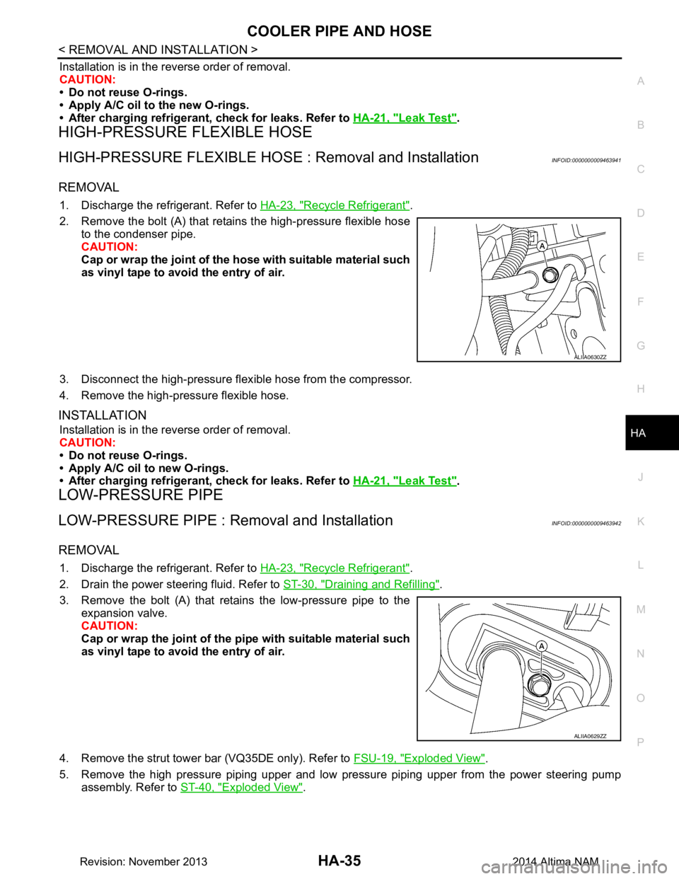
2. Remove the bolt (A) that retains the high-pressure flexible hose to the condenser pipe.
CAUTION:
Cap or wrap the joint of the ho se with suitable material such
as vinyl tape to avoid the entry of air.
3. Disconnect the high-pressure flex ible hose from the compressor.
4. Remove the high-pressure flexible hose.
INSTALLATION
Installation is in the reverse order of removal.
CAUTION:
• Do not reuse O-rings.
• Apply A/C oil to new O-rings.
• After charging refrigerant, check for leaks. Refer to HA-21, "Leak Test"
.
LOW-PRESSURE PIPE
LOW-PRESSURE PIPE : Re moval and InstallationINFOID:0000000009463942
REMOVAL
1. Discharge the refrigerant. Refer to HA-23, "Recycle Refrigerant".
2. Drain the power steering fluid. Refer to ST-30, "Draining and Refilling"
.
3. Remove the bolt (A) that retains the low-pressure pipe to the expansion valve.
CAUTION:
Cap or wrap the joint of the pi pe with suitable material such
as vinyl tape to avoid the entry of air.
4. Remove the strut tower bar (VQ35DE only). Refer to FSU-19, "Exploded View"
.
5. Remove the high pressure piping upper and low pressure piping upper from the power steering pump assembly. Refer to ST-40, "Exploded View"
.
ALIIA0630ZZ
ALIIA0629ZZ
Revision: November 20132014 Altima NAM
Page 2642 of 4801
HA-36
< REMOVAL AND INSTALLATION >
COOLER PIPE AND HOSE
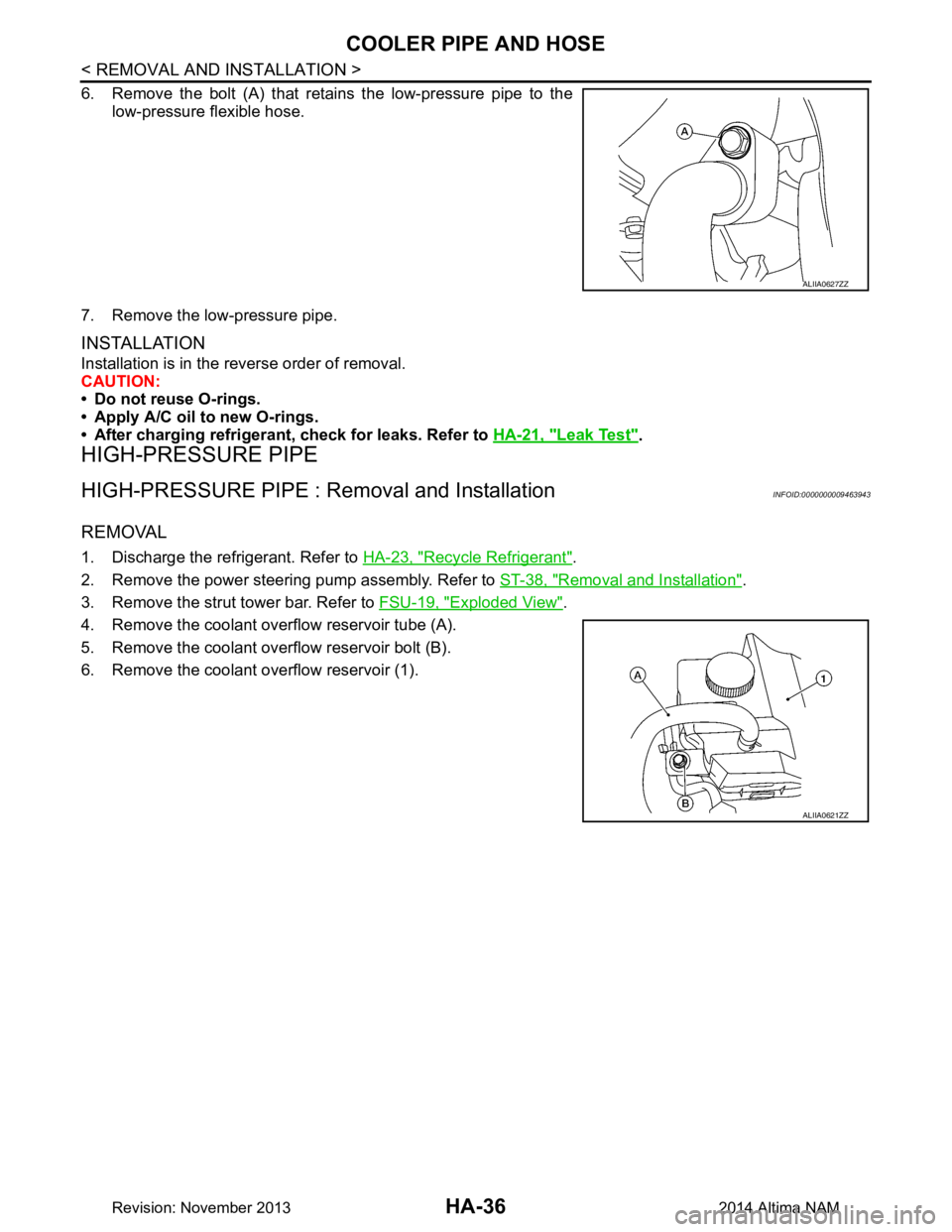
6. Remove the bolt (A) that retains the low-pressure pipe to thelow-pressure flexible hose.
7. Remove the low-pressure pipe.
INSTALLATION
Installation is in the reverse order of removal.
CAUTION:
• Do not reuse O-rings.
• Apply A/C oil to new O-rings.
• After charging refrigerant, check for leaks. Refer to HA-21, "Leak Test"
.
HIGH-PRESSURE PIPE
HIGH-PRESSURE PIPE : Removal and InstallationINFOID:0000000009463943
REMOVAL
1. Discharge the refrigerant. Refer to HA-23, "Recycle Refrigerant".
2. Remove the power steering pump assembly. Refer to ST-38, "Removal and Installation"
.
3. Remove the strut tower bar. Refer to FSU-19, "Exploded View"
.
4. Remove the coolant overflow reservoir tube (A).
5. Remove the coolant overflow reservoir bolt (B).
6. Remove the coolant overflow reservoir (1).
ALIIA0627ZZ
ALIIA0621ZZ
Revision: November 20132014 Altima NAM
Page 2643 of 4801
COOLER PIPE AND HOSEHA-37
< REMOVAL AND INSTALLATION >
C
D E
F
G H
J
K L
M A
B
HA
N
O P
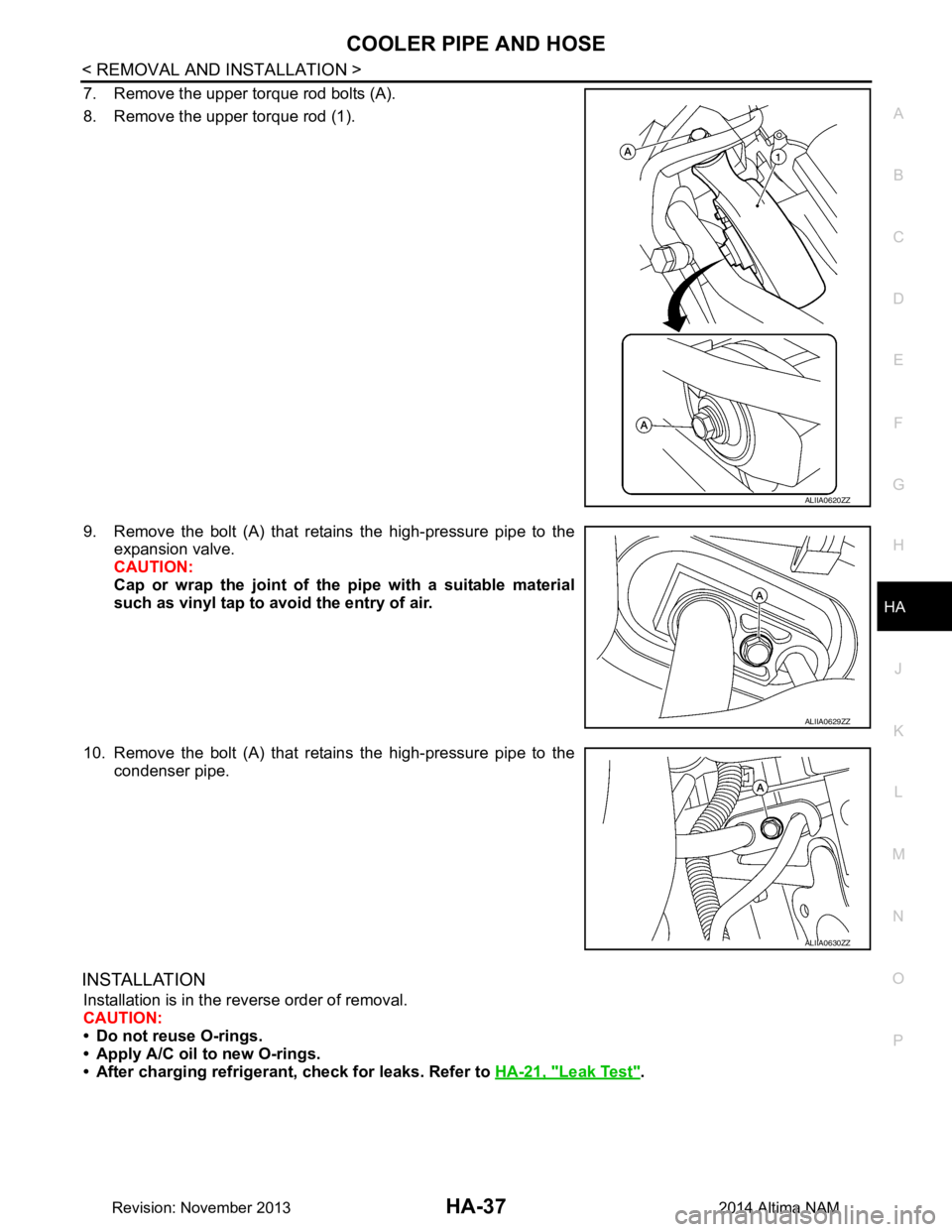
7. Remove the upper torque rod bolts (A).
8. Remove the upper torque rod (1).
9. Remove the bolt (A) that retains the high-pressure pipe to the expansion valve.
CAUTION:
Cap or wrap the joint of the pipe with a suitable material
such as vinyl tap to avo id the entry of air.
10. Remove the bolt (A) that retains the high-pressure pipe to the condenser pipe.
INSTALLATION
Installation is in the reverse order of removal.
CAUTION:
• Do not reuse O-rings.
• Apply A/C oil to new O-rings.
• After charging refrigerant, check for leaks. Refer to HA-21, "Leak Test"
.
ALIIA0620ZZ
ALIIA0629ZZ
ALIIA0630ZZ
Revision: November 20132014 Altima NAM
Page 2645 of 4801
CONDENSERHA-39
< REMOVAL AND INSTALLATION >
C
D E
F
G H
J
K L
M A
B
HA
N
O P
4. Disconnect the harness connector from the refrigerant pressure sensor.
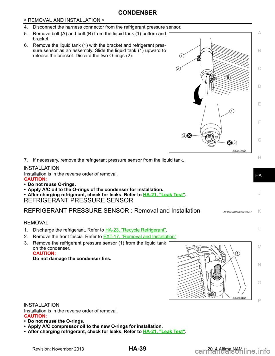
5. Remove bolt (A) and bolt (B) from the liquid tank (1) bottom and bracket.
6. Remove the liquid tank (1) with the bracket and refrigerant pres-
sure sensor as an assembly. Slide the liquid tank (1) upward to
release the bracket. Discard the two O-rings (2).
7. If necessary, remove the refrigerant pressure sensor from the liquid tank.
INSTALLATION
Installation is in the reverse order of removal.
CAUTION:
• Do not reuse O-rings.
• Apply A/C oil to the O-rings of the condenser for installation.
• After charging refrigerant, check for leaks. Refer to HA-21, "Leak Test"
.
REFRIGERANT PRESSURE SENSOR
REFRIGERANT PRESSURE SENSOR : Removal and InstallationINFOID:0000000009463947
REMOVAL
1. Discharge the refrigerant. Refer to HA-23, "Recycle Refrigerant".
2. Remove the front fascia. Refer to EXT-17, "Removal and Installation"
.
3. Remove the refrigerant pressure sensor (1) from the liquid tank on the condenser.
CAUTION:
Do not damage the condenser fins.
INSTALLATION
Installation is in the reverse order of removal.
CAUTION:
• Do not reuse the O-rings.
• Apply A/C compressor oil to th e new O-rings for installation.
• After charging refrigerant, check for leaks. Refer to HA-21, "Leak Test"
.
ALIIA0422ZZ
ALIIA0004ZZ
Revision: November 20132014 Altima NAM
Page 2654 of 4801
![NISSAN TEANA 2014 Service Manual
PRECAUTIONSHAC-5
< PRECAUTION > [AUTOMATIC AIR CONDITIONER]
C
D E
F
G H
J
K L
M A
B
HAC
N
O P
PRECAUTION
PRECAUTIONS
Precaution for Supplemental Restraint System (SRS) "AIR BAG" and "SEAT BELT
PR NISSAN TEANA 2014 Service Manual
PRECAUTIONSHAC-5
< PRECAUTION > [AUTOMATIC AIR CONDITIONER]
C
D E
F
G H
J
K L
M A
B
HAC
N
O P
PRECAUTION
PRECAUTIONS
Precaution for Supplemental Restraint System (SRS) "AIR BAG" and "SEAT BELT
PR](/manual-img/5/57390/w960_57390-2653.png)
PRECAUTIONSHAC-5
< PRECAUTION > [AUTOMATIC AIR CONDITIONER]
C
D E
F
G H
J
K L
M A
B
HAC
N
O P
PRECAUTION
PRECAUTIONS
Precaution for Supplemental Restraint System (SRS) "AIR BAG" and "SEAT BELT
PRE-TENSIONER"
INFOID:0000000009951773
The Supplemental Restraint System such as “A IR BAG” and “SEAT BELT PRE-TENSIONER”, used along
with a front seat belt, helps to reduce the risk or severi ty of injury to the driver and front passenger for certain
types of collision. Information necessary to service t he system safely is included in the SR and SB section of
this Service Manual.
WARNING:
• To avoid rendering the SRS inoper ative, which could increase the risk of personal injury or death in
the event of a collision which would result in air bag inflation, all maintenance must be performed by
an authorized NISSAN/INFINITI dealer.
• Improper maintenance, including in correct removal and installation of the SRS, can lead to personal
injury caused by unintentional act ivation of the system. For removal of Spiral Cable and Air Bag
Module, see the SR section.
• Do not use electrical test equipm ent on any circuit related to the SRS unless instructed to in this
Service Manual. SRS wiring harnesses can be identi fied by yellow and/or orange harnesses or har-
ness connectors.
PRECAUTIONS WHEN USING POWER TOOLS (AIR OR ELECTRIC) AND HAMMERS
WARNING:
• When working near the Airbag Diagnosis Sensor Un it or other Airbag System sensors with the Igni-
tion ON or engine running, DO NOT use air or el ectric power tools or strike near the sensor(s) with a
hammer. Heavy vibration could activate the sensor( s) and deploy the air bag(s), possibly causing
serious injury.
• When using air or electric power tools or hammers , always switch the Ignition OFF, disconnect the
battery and wait at least three mi nutes before performing any service.
Precaution for WorkINFOID:0000000009463086
• When removing or disassembling each component, be ca reful not to damage or deform it. If a component
may be subject to interference, be sure to protect it with a shop cloth.
• When removing (disengaging) components with a screwdriver or similar tool, be sure to wrap the component with a shop cloth or vinyl tape to protect it.
• Protect the removed parts with a shop cloth and prevent them from being dropped.
• Replace a deformed or damaged clip.
• If a part is specified as a non-reusabl e part, always replace it with a new one.
• Be sure to tighten bolts and nuts securely to the specified torque.
• After installation is complete, be sure to check that each part works properly.
• Follow the steps below to clean components:
- Water soluble dirt:
• Dip a soft cloth into lukewarm water, wring the water out of the cloth and wipe the dirty area.
• Then rub with a soft, dry cloth.
-Oily dirt:
• Dip a soft cloth into lukewarm water with mild detergent (concentration: within 2 to 3%) and wipe the dirty area.
• Then dip a cloth into fresh water, wring the water out of the cloth and wipe the detergent off.
• Then rub with a soft, dry cloth.
- Do not use organic solvent such as thinner, benzene, alcohol or gasoline.
- For genuine leather seats, use a genuine leather seat cleaner.
Working with HFC-134a (R-134a)INFOID:0000000009463087
WARNING:
• CFC-12 (R-12) refrigerant and HFC-134a (R-134a) refr igerant are not compatible. If the refrigerants
are mixed compressor failure is likely to occur. Refer to HA-25, "Inspection"
. To determine the purity
of HFC-134a (R-134a) in the vehicle and recovery tank, use Refrigerant Recovery/Recycling Recharg-
ing equipment and Refrigerant Identifier.
Revision: November 20132014 Altima NAMRevision: November 20132014 Altima NAM