2014 NISSAN TEANA window
[x] Cancel search: windowPage 1957 of 4801
![NISSAN TEANA 2014 Service Manual
ELECTRICAL LOAD SIGNALEC-957
< DTC/CIRCUIT DIAGNOSIS > [VQ35DE]
C
D E
F
G H
I
J
K L
M A
EC
NP
O
ELECTRICAL LOAD SIGNAL
DescriptionINFOID:0000000009462836
The electrical load signal (Headlamp switch NISSAN TEANA 2014 Service Manual
ELECTRICAL LOAD SIGNALEC-957
< DTC/CIRCUIT DIAGNOSIS > [VQ35DE]
C
D E
F
G H
I
J
K L
M A
EC
NP
O
ELECTRICAL LOAD SIGNAL
DescriptionINFOID:0000000009462836
The electrical load signal (Headlamp switch](/manual-img/5/57390/w960_57390-1956.png)
ELECTRICAL LOAD SIGNALEC-957
< DTC/CIRCUIT DIAGNOSIS > [VQ35DE]
C
D E
F
G H
I
J
K L
M A
EC
NP
O
ELECTRICAL LOAD SIGNAL
DescriptionINFOID:0000000009462836
The electrical load signal (Headlamp switch signal, rear
window defogger switch signal, etc.) is transferred via
the CAN communication.
Component Function CheckINFOID:0000000009462837
1.CHECK REAR WINDOW DEF OGGER SWITCH FUNCTION
1. Turn ignition switch ON.
2. Connect CONSULT and select “DATA MONITOR” mode.
3. Select “LOAD SIGNAL” and check indication under the following conditions.
Is the inspection result normal?
YES >> GO TO 2.
NO >> Proceed to EC-957, "Diagnosis Procedure"
.
2.CHECK LIGHTING SWITCH FUNCTION
Check “LOAD SIGNAL” indication under the following conditions.
Is the inspection result normal?
YES >> GO TO 3.
NO >> Proceed to EC-957, "Diagnosis Procedure"
.
3.CHECK HEATER FAN CONTROL SWITCH FUNCTION
Select “HEATER FAN SW” and check indication under the following conditions.
Is the inspection result normal?
YES >> INSPECTION END
NO >> Proceed to EC-957, "Diagnosis Procedure"
.
Diagnosis ProcedureINFOID:0000000009462838
1.INSPECTION START
Confirm the malfunctioning circuit (rear window defogger, headlamp or heater fan). Refer to EC-957, "Compo-
nent Function Check".
Which circuit is related to the incident?
Rear window defogger>>GO TO 2.
Headlamp>>GO TO 3.
Heater fan>>GO TO 4.
2.CHECK REAR WINDOW DEFOGGER SYSTEM
Check rear window defogger system. Refer to DEF-16, "Work Flow"
.
Monitor item Condition Indication
LOAD SIGNAL Rear window defogger switch ON ON
OFF OFF
Monitor item Condition Indication
LOAD SIGNAL Lighting switch ON at 2nd position ON
OFF OFF
Monitor item Condition Indication
HEATER FAN SW Heater fan control switchON ON
OFF OFF
Revision: November 20132014 Altima NAMRevision: November 20132014 Altima NAM
Page 1998 of 4801
![NISSAN TEANA 2014 Service Manual
EC-998
< SERVICE DATA AND SPECIFICATIONS (SDS) [VQ35DE]
SERVICE DATA AND SPECIFICATIONS (SDS)
SERVICE DATA AND SPECIFICATIONS (SDS)
SERVICE DATA AND SPECIFICATIONS (SDS)
Idle SpeedINFOID:000000000946 NISSAN TEANA 2014 Service Manual
EC-998
< SERVICE DATA AND SPECIFICATIONS (SDS) [VQ35DE]
SERVICE DATA AND SPECIFICATIONS (SDS)
SERVICE DATA AND SPECIFICATIONS (SDS)
SERVICE DATA AND SPECIFICATIONS (SDS)
Idle SpeedINFOID:000000000946](/manual-img/5/57390/w960_57390-1997.png)
EC-998
< SERVICE DATA AND SPECIFICATIONS (SDS) [VQ35DE]
SERVICE DATA AND SPECIFICATIONS (SDS)
SERVICE DATA AND SPECIFICATIONS (SDS)
SERVICE DATA AND SPECIFICATIONS (SDS)
Idle SpeedINFOID:0000000009462872
*: Under the following conditions
• A/C switch: OFF
• Electric load: OFF (Lights, heater fan & rear window defogger)
• Steering wheel: Kept in straight-ahead position
Ignition TimingINFOID:0000000009462873
*: Under the following conditions
• A/C switch: OFF
• Electric load: OFF (Lights, heater fan & rear window defogger)
• Steering wheel: Kept in straight-ahead position
Calculated Load ValueINFOID:0000000009462874
Mass Air Flow SensorINFOID:0000000009462875
*: Engine is warmed up to normal operating temperature and running under no load. Condition Specification
No load* (in P or N position) 650 ± 50 rpm
Condition Specification
No load* (in P or N position) 12 ± 2 ° BTDC
Condition Specification (Using CONSULT or GST)
At idle 10 – 35 %
At 2,500 rpm 10 – 35 %
Supply voltageBattery voltage (11 – 14 V)
Output voltage at idle (in N position) 0.9 – 1.2 V*
Mass air flow (Using CONSULT or GST) 2.0 – 6.0 g/s at idle*
7.0 – 20.0 g/s at 2,500 rpm*
Revision: November 20132014 Altima NAMRevision: November 20132014 Altima NAM
Page 2283 of 4801

DIAGNOSIS SYSTEM (BCM)EXL-17
< SYSTEM DESCRIPTION >
C
D E
F
G H
I
J
K
M A
B
EXL
N
O P
DIAGNOSIS SYSTEM (BCM)
COMMON ITEM
COMMON ITEM : CONSULT Function (BCM - COMMON ITEM)INFOID:0000000009956424
CAUTION:
After disconnecting the CONSULT vehicle interface (VI) from the data link connector, the ignition must
be cycled OFF → ON (for at least 5 seconds) → OFF. If this step is not performed, the BCM may not go
to ”sleep mode”, potentiall y causing a discharged battery and a no-start condition.
APPLICATION ITEM
CONSULT performs the following functions via CAN communication with BCM.
SYSTEM APPLICATION
BCM can perform the following functions.
Direct Diagnostic Mode Description
Ecu Identification The BCM part number is displayed.
Self Diagnostic Result The BCM self diagnostic results are displayed.
Data Monitor The BCM input/output data is displayed in real time.
Active Test The BCM activates outputs to test components.
Work support The settings for BCM functions can be changed.
Configuration • The vehicle specification can be read and saved.
• The vehicle specification can be written when replacing BCM.
CAN Diag Support Mntr The result of transmit/receive diagnosis of CAN communication is displayed.
System Sub System Direct Diagnostic Mode
Ecu Identification
Self Diagnostic Result
Data Monitor
Active Test
Work support
Configuration
CAN Diag Su pport Mntr
Door lock DOOR LOCK ××××
Rear window defogger REAR DEFOGGER ×××
Warning chime BUZZER ××
Interior room lamp timer INT LAMP ×××
Remote keyless entry system MULTI REMOTE ENT ×××
Exterior lamp HEADLAMP ×××
Wiper and washer WIPER ×××
Turn signal and hazard warning lamps FLASHER ××
Air conditioner AIR CONDITIONER ×
Intelligent Key system INTELLIGENT KEY ××××
Combination switch COMB SW ×
BCM BCM × × ×××
Immobilizer IMMU ×××
Interior room lamp battery saver BATTERY SAVER ××
Trunk open TRUNK ×
Vehicle security system THEFT ALM ×××
Revision: November 20132014 Altima NAMRevision: November 20132014 Altima NAM
Page 2549 of 4801

RECOMMENDED CHEMICAL PRODUCTS AND SEALANTS
GI-21
< HOW TO USE THIS MANUAL >
C
D E
F
G H
I
J
K L
M B
GI
N
O PRECOMMENDED CHEMICAL PRODUCTS AND SEALANTS
Recommended Chemical Products and SealantsINFOID:0000000009462982
Refer to the following chart for help in selecting the appropriate chemical product or sealant.
Product Description Purpose Nissan North America
Part No. (USA) Nissan Canada Part
No. (Canada) Aftermarket Cross-
reference Part Nos.
1 Rear View Mirror Adhe-
sive Used to permanently re-
mount rear view mirrors to
windows. 999MP-AM000P 99998-50505 Permatex 81844
2 Anaerobic Liquid Gas-
ket For metal-to-metal flange
sealing.
Can fill a 0.38 mm (0.015
inch) gap and provide in-
stant sealing for most pow-
ertrain applications. 999MP-AM001P 99998-50503
Permatex 51813 and
51817
3 High Performance
Thread Sealant Provides instant sealing on
any threaded straight or
parallel threaded fitting.
(Thread sealant only, no
locking ability.)
• Do not use on plastic. 999MP-AM002P 999MP-AM002P Permatex 56521
4 Silicone RTV Gasket Maker 999MP-AM003P
(Ultra Grey) 99998-50506
(Ultra Grey) Permatex Ultra Grey
82194;
Three Bond
1207,1215, 1216,
1217F, 1217G and
1217H
Nissan RTV Part No.
999MP-A7007
5 High Temperature,
High Strength Thread
Locking Sealant (Red) Threadlocker 999MP-AM004P 999MP-AM004P Permatex 27200;
Three Bond 1360,
1360N, 1305 N&P,
1307N, 1335,
1335B, 1363B,
1377C, 1386B, D&E
and 1388
Loctite 648
6 Medium Strength
Thread Locking Seal-
ant (Blue) Threadlocker (service tool
removable) 999MP-AM005P 999MP-AM005P Permatex 24200,
24206, 24240,
24283 and 09178;
Three Bond 1322,
1322N, 1324 D&N,
1333D, 1361C,
1364D, 1370C and
1374
Revision: November 20132014 Altima NAMRevision: November 20132014 Altima NAM
Page 2573 of 4801

SERVICE INFORMATION FOR ELECTRICAL INCIDENTGI-45
< BASIC INSPECTION >
C
D E
F
G H
I
J
K L
M B
GI
N
O P
An unclamped or loose harness can cause wiring to be pinched by seat components (such as slide guides)
during vehicle vibration. If the wiring runs under s eating areas, inspect wire routing for possible damage or
pinching.
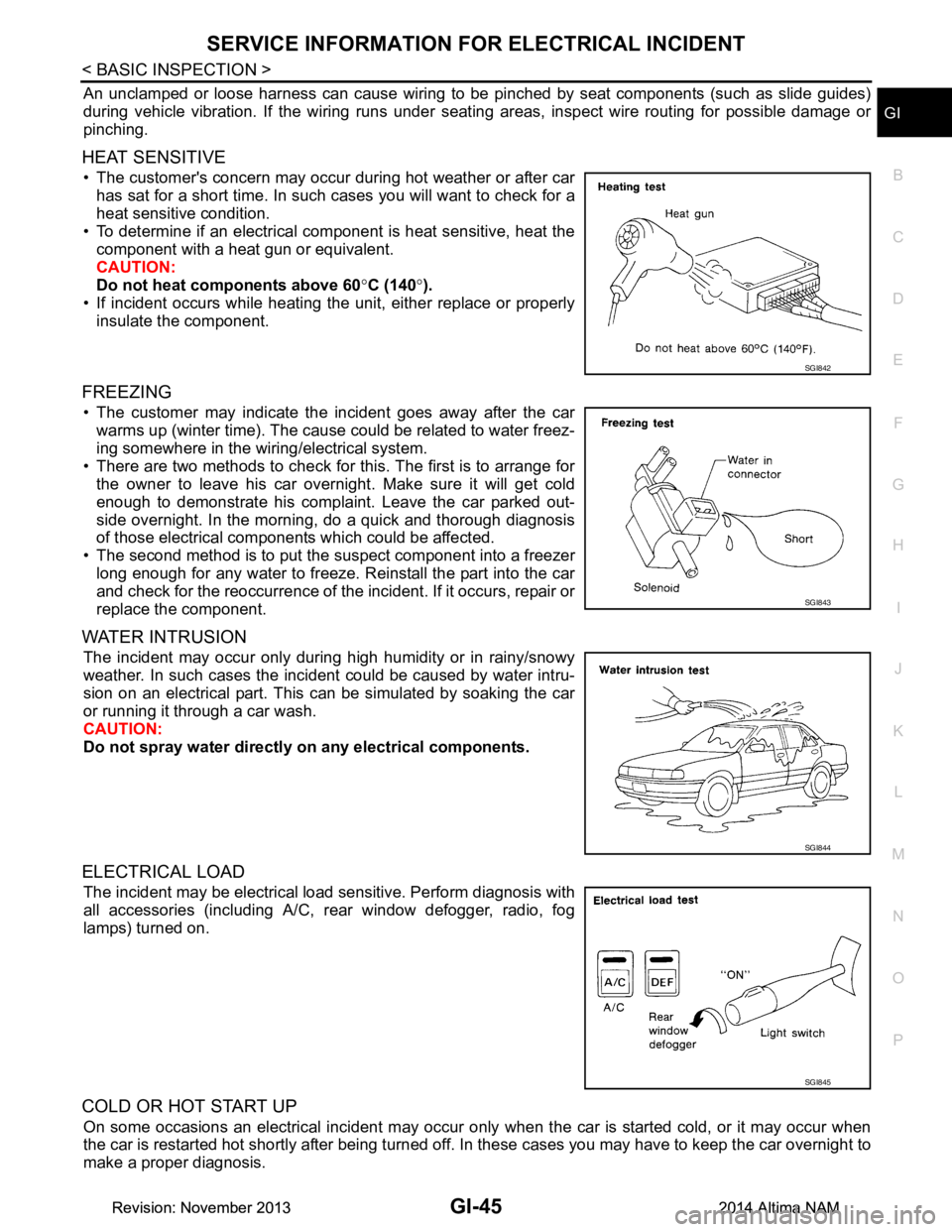
HEAT SENSITIVE
• The customer's concern may occur during hot weather or after car has sat for a short time. In such cases you will want to check for a
heat sensitive condition.
• To determine if an electrical component is heat sensitive, heat the component with a heat gun or equivalent.
CAUTION:
Do not heat components above 60 °C (140 °).
• If incident occurs while heating t he unit, either replace or properly
insulate the component.
FREEZING
• The customer may indicate the incident goes away after the car warms up (winter time). The cause could be related to water freez-
ing somewhere in the wiring/electrical system.
• There are two methods to check for this. The first is to arrange for the owner to leave his car overnight. Make sure it will get cold
enough to demonstrate his complaint. Leave the car parked out-
side overnight. In the morning, do a quick and thorough diagnosis
of those electrical components which could be affected.
• The second method is to put the suspect component into a freezer long enough for any water to freeze. Reinstall the part into the car
and check for the reoccurrence of the incident. If it occurs, repair or
replace the component.
WATER INTRUSION
The incident may occur only during high humidity or in rainy/snowy
weather. In such cases the incident could be caused by water intru-
sion on an electrical part. This c an be simulated by soaking the car
or running it through a car wash.
CAUTION:
Do not spray water directly on any electrical components.
ELECTRICAL LOAD
The incident may be electrical load sensitive. Perform diagnosis with
all accessories (including A/C, rear window defogger, radio, fog
lamps) turned on.
COLD OR HOT START UP
On some occasions an electrical incident may occur only when the car is started cold, or it may occur when
the car is restarted hot shortly after being turned off. In these cases you may have to keep the car overnight to
make a proper diagnosis.
SGI842
SGI843
SGI844
SGI845
Revision: November 20132014 Altima NAMRevision: November 20132014 Altima NAM
Page 2581 of 4801

GW-1
BODY EXTERIOR, DOORS, ROOF & VEHICLE SECURITY
C
D E
F
G H
I
J
L
M
SECTION GW
A
B
GW
N
O P
CONTENTS
GLASS & WINDOW SYSTEM
PRECAUTION ................ ...............................2
PRECAUTIONS .............................................. .....2
Precaution for Supplemental Restraint System
(SRS) "AIR BAG" and "SEAT BELT PRE-TEN-
SIONER" ............................................................. ......
2
Procedure without Cowl Top Cover .......................2
Handling for Adhesive and Primer ............................2
Precaution for Work ..................................................2
PREPARATION ............................................4
PREPARATION .............................................. .....4
Special Service Tools ........................................ ......4
Commercial Service Tools .......................................4
SYMPTOM DIAGNOSIS ...............................5
SQUEAK AND RATTLE TROUBLE DIAG-
NOSES ........................................................... .....
5
Work Flow ........................................................... ......5
Generic Squeak and Rattle Troubleshooting ............6
Diagnostic Worksheet ...............................................9
REMOVAL AND INSTALLATION ...............11
WINDSHIELD GLASS .................................... ....11
Exploded View .................................................... ....11
Removal and Installation .........................................12
FRONT DOOR GLASS .....................................14
Removal and Installation ..................................... ....14
Inspection and Adjustment ......................................15
FRONT REGULATOR .......................................16
Exploded View .........................................................16
Removal and Installation - Front Regulator .............16
Inspection and Adjustment .................................. ....18
Removal and Installation - Front Power Window
Motor ................................................................... ....
18
REAR DOOR GLASS .......................................19
Removal and Installation .........................................19
REAR REGULATOR .........................................20
Exploded View .........................................................20
Removal and Installation - Rear Regulator ..............20
Removal and Installation - Rear Power Window
Motor ................................................................... ....
22
SIDE WINDOW GLASS ....................................23
Components ............................................................23
Removal and Installation .........................................23
REAR WINDOW GLASS ..................................25
Exploded View .........................................................25
Removal and Installation .........................................25
Revision: November 20132014 Altima NAM
Page 2592 of 4801

GW-12
< REMOVAL AND INSTALLATION >
WINDSHIELD GLASS
Removal and Installation
INFOID:0000000009463661
REMOVAL
1. Partially remove the headlining (front edge). Refer to INT-30, "Removal and Installation".
2. Remove inside mirror. Refer to MIR-19, "Removal and Installation"
.
3. Remove the cowl top cover. Refer to EXT-24, "Removal and Installation"
.
4. Remove roof side moldings (LH/RH). Refer to EXT-36, "Removal and Installation"
.
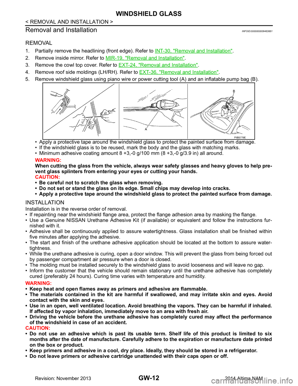
5. Remove windshield glass using piano wire or pow er cutting tool (A) and an inflatable pump bag (B).
• Apply a protective tape around the windshield gla ss to protect the painted surface from damage.
• If the windshield glass is to be reused, mark the body and the glass with matching marks.
• Minimum adhesive coating amount 8 +3,- 0 g/100 mm (8 +3,-0 g/3.9 in) all around.
WARNING:
When cutting the glass from the vehicle, always wear safety glasses and heavy gloves to help pre-
vent glass splinters from entering your eyes or cutting your hands.
CAUTION:
• Be careful not to scratch the glass when removing.
• Do not set or stand the glass on its ed ge. Small chips may develop into cracks.
• Apply a protective tape around the windshield glass to protect the painted surface from damage.
INSTALLATION
Installation is in the reverse order of removal.
• If repainting near the windshield flange area, pr otect the flange adhesion area by masking the flange.
• Use a Genuine NISSAN Urethane Adhesive Kit (if availabl e) or equivalent and follow the instructions fur-
nished with it.
• Adhesive shall be continuously applied to assure watert ightness. Glass installation shall be finished within
five minutes after applying the adhesive.
• The start and finish of the urethane adhesive application should be located at the bottom to assure water-
tightness.
• While the urethane adhesive is curing, open a door window . This will prevent the glass from being forced out
by passenger compartment air pressure when a door is closed.
• The molding must be installed securely to the windshield glass to avoid looseness and will leave no gap.
• Inform the customer that the vehicle should rema in stationary until the urethane adhesive has completely
cured (preferably 24 hours). Curing time varies with temperature and humidity.
WARNING:
• Keep heat and open flames away as primers and adhesive are flammable.
• The materials contained in the kit are harmful if swallowed, and may irritate skin and eyes. Avoid
contact with the skin and eyes.
• Use in an open, well ventilated location. Avoid br eathing the vapors. They can be harmful if inhaled.
If affected by vapor inhalation, imme diately move to an area with fresh air.
• Driving the vehicle before the urethane adhesive has completely cured may affect the performance
of the windshield in case of an accident.
CAUTION:
• Do not use an adhesive which is past its usable te rm. Shelf life of this product is limited to six
months after the date of manufacture. Carefully a dhere to the expiration or manufacture date printed
on the box or product.
• Keep primers and adhesive in a c ool, dry place. Ideally, they should be stored in a refrigerator.
• Do not leave primers or adhesive cartridge unattended with their caps open or off.
PIIB5779E
Revision: November 20132014 Altima NAM
Page 2594 of 4801

GW-14
< REMOVAL AND INSTALLATION >
FRONT DOOR GLASS
FRONT DOOR GLASS
Removal and InstallationINFOID:0000000009463662
WARNING:
• Before servicing, turn ignition sw itch OFF, disconnect both battery terminals and wait at least three
minutes.
• Do not use air tools or el ectric tools for servicing.
REMOVAL
NOTE:
LH side shown; RH side similar
1. Disconnect the battery positive and negative terminal. Refer to PG-73, "Removal and Installation (Bat-
tery)".
2. Remove the front door finisher. Refer to INT-15, "Removal and Installation"
.
3. Remove the vapor barrier. CAUTION:
Use care to not damage or tear vapor barrier during removal.
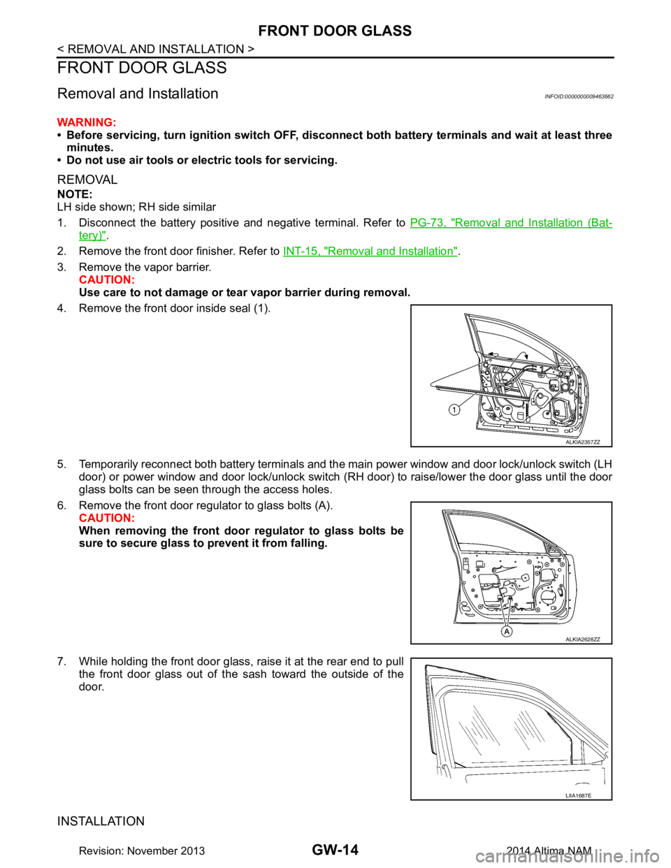
4. Remove the front door inside seal (1).
5. Temporarily reconnect both battery terminals and the main power window and door lock/unlock switch (LH door) or power window and door lock/unlock switch ( RH door) to raise/lower the door glass until the door
glass bolts can be seen through the access holes.
6. Remove the front door regul ator to glass bolts (A).
CAUTION:
When removing the front door regulator to glass bolts be
sure to secure glass to prevent it from falling.
7. While holding the front door glass, raise it at the rear end to pull the front door glass out of the sash toward the outside of the
door.
INSTALLATION
ALKIA2357ZZ
ALKIA2628ZZ
LIIA1687E
Revision: November 20132014 Altima NAM