2014 NISSAN TEANA window
[x] Cancel search: windowPage 761 of 4801

DEF-36
< SYMPTOM DIAGNOSIS >
REAR WINDOW DEFOGGER DOES NOT OPERATE BUT BOTH OF DOOR MIR-
ROR DEFOGGER OPERATE.
REAR WINDOW DEFOGGER DOES NO T OPERATE BUT BOTH OF DOOR
MIRROR DEFOGGER OPERATE.
Diagnosis ProcedureINFOID:0000000009463055
1. CHECK REAR WINDOW DEFOGGER POWER SUPPLY AND GROUND CIRCUIT
Check rear window defogger power supply and ground circuit.
Refer to DEF-28, "Component Function Check"
.
Is the inspection result normal?
YES >> Refer to GI-43, "Intermittent Incident".
NO >> Repair or replace the malfunctioning parts.
Revision: November 20132014 Altima NAMRevision: November 20132014 Altima NAM
Page 762 of 4801

BOTH DOORS MIRROR DEFOGGER DON’T OPERATE BUT REAR WINDOW DEFOGGER OPERATES
DEF-37
< SYMPTOM DIAGNOSIS >
C
D E
F
G H
I
J
K
M A
B
DEF
N
O P
BOTH DOORS MIRROR DEFOGGER DON’T OPERATE BUT REAR WIN-
DOW DEFOGGER OPERATES
Diagnosis ProcedureINFOID:0000000009463056
Regarding Wiring Diagram information, refer to DEF-11, "Wiring Diagram".
1. CHECK DOOR MIRROR DEFOGGER FUSE
Check if the following fuse in fuse block (J/B) is blown.
Is the inspection result normal?
YES >> GO TO 2.
NO >> Replace the blown fuse after repairing the affected circuit.
2. CHECK DOOR MIRROR DEF OGGER POWER SUPPLY CIRCUIT
1. Turn ignition switch ON.
2. Check voltage between fuse block (J/B) harness connector and ground.
Is the inspection result normal?
YES >> GO TO 3.
NO >> Replace fuse block (J/B).
3. CHECK BOTH DOOR MIRROR DEFOGGER
1. Check door mirror LH. Refer to DEF-30, "Component Function Check"
.
2. Check door mirror RH. Refer to DEF-32, "Component Function Check"
.
Is the inspection result normal?
YES >> Check intermittent incident. Refer to GI-43, "Intermittent Incident".
NO >> Repair or replace the malfunctioning parts.
COMPONENT PARTS AMPERE FUSE NO.
Fuse block (J/B) 10A 22
(+) (–) Condition Voltage (V)
(Approx.)
Fuse block (J/B)
Connector Terminal
M5 5P Ground Rear window de-
fogger switch ON Battery voltage
OFF 0
Revision: November 20132014 Altima NAMRevision: November 20132014 Altima NAM
Page 765 of 4801

DEF-40
< SYMPTOM DIAGNOSIS >
REAR WINDOW DEFOGGER SWITCH DOES NOT LIGHT, BUT REAR WINDOW
DEFOGGER OPERATES
REAR WINDOW DEFOGGER SWITCH DOES NOT LIGHT, BUT REAR WIN-
DOW DEFOGGER OPERATES
Diagnosis ProcedureINFOID:0000000009463059
1. CHECK REAR WINDOW DEFOGGER SWITCH
Check that the rear window defogger switch is operating normally.
Is the inspection result normal?
YES >> Refer to GI-43, "Intermittent Incident".
NO >> Refer to DEF-19, "WITH MANUAL A/C : Diagnosis Procedure"
or DEF-22, "WITH AUTO A/C :
Diagnosis Procedure".
Revision: November 20132014 Altima NAMRevision: November 20132014 Altima NAM
Page 783 of 4801

COMPONENT PARTSDLK-15
< SYSTEM DESCRIPTION >
C
D E
F
G H
I
J
L
M A
B
DLK
N
O P
POWER DOOR LOCK SYSTEM : Component DescriptionINFOID:0000000009461767
INTELLIGENT KEY SYSTEM
1. BCM (view with combination meter
removed) 2. Main power window and door lock/
unlock switch 3. Power window and door lock/unlock
switch RH
4. Front door lock actuator LH 5. Front door switch LH 6. Front door lock actuator RH
7. Front door switch RH 8. Rear door lock actuator LH 9. Rear door switch LH
10. Rear door lock actuator RH 11. Rear door switch RH 12. Trunk lamp switch and trunk release solenoid
Item Function
BCM Controls the door lock system
Door switch Inputs door open/close condition to BCM
Door lock and unlock switch • Detects if door lock and unlock switch is press/release
• Integrated in the main power window and door lock/unlock switch and power window and
door lock/unlock switch (RH)
Door lock actuator Output lock/unlock signal from BCM and locks/unlocks each door
Trunk lamp switch and release so-
lenoid Output release signal from BCM and release trunk lid
Revision: November 20132014 Altima NAMRevision: November 20132014 Altima NAM
Page 789 of 4801

SYSTEM (POWER DOOR LOCK SYSTEM)DLK-21
< SYSTEM DESCRIPTION >
C
D E
F
G H
I
J
L
M A
B
DLK
N
O P
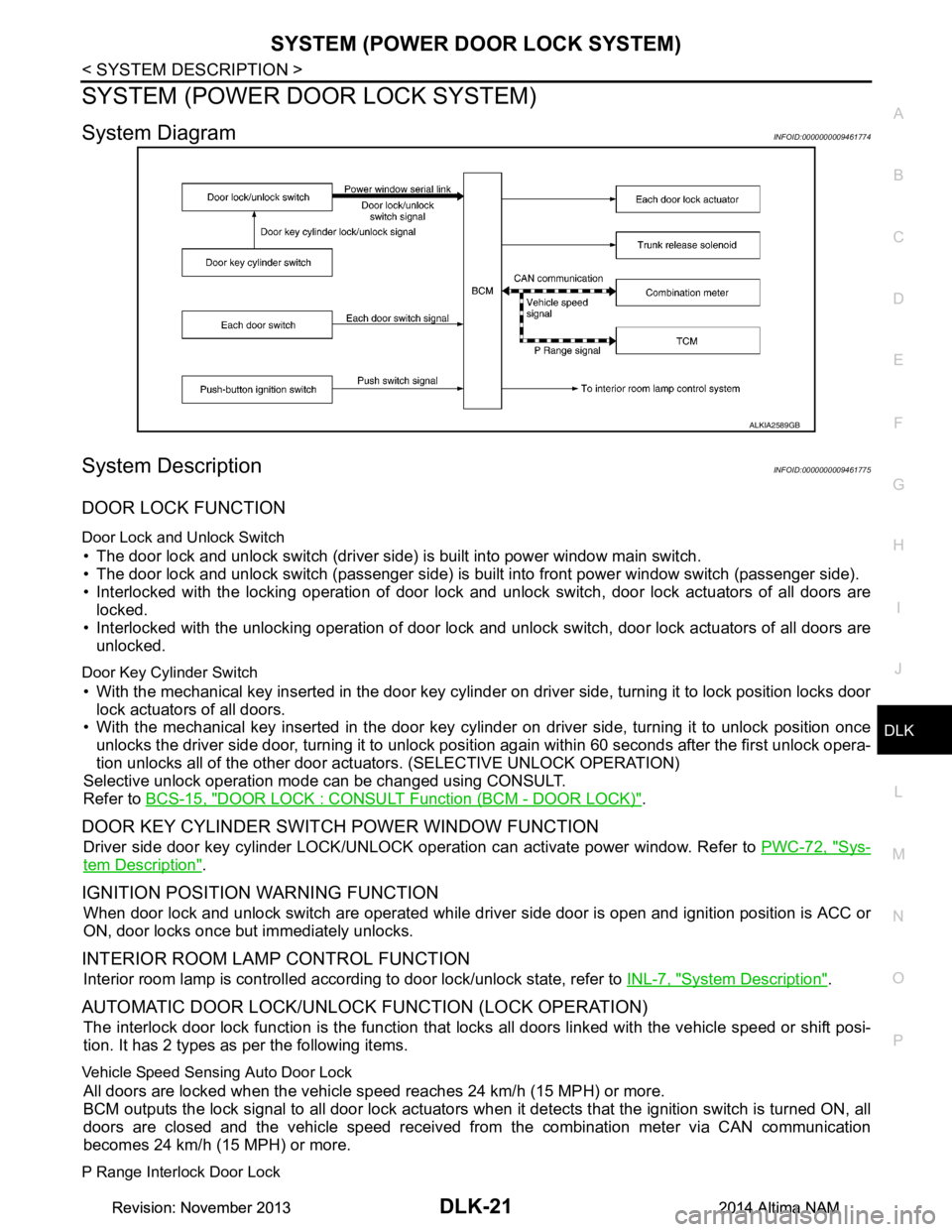
SYSTEM (POWER DOOR LOCK SYSTEM)
System DiagramINFOID:0000000009461774
System DescriptionINFOID:0000000009461775
DOOR LOCK FUNCTION
Door Lock and Unlock Switch
• The door lock and unlock switch (driver side) is built into power window main switch.
• The door lock and unlock switch (passenger side) is built into front power window switch (passenger side).
• Interlocked with the locking operation of door lock and unlock switch, door lock actuators of all doors are
locked.
• Interlocked with the unlocking operation of door lock and unlock switch, door lock actuators of all doors are
unlocked.
Door Key Cylinder Switch
• With the mechanical key inserted in the door key cylinder on driver side, turning it to lock position locks door
lock actuators of all doors.
• With the mechanical key inserted in the door key cylinder on driver side, turning it to unlock position once
unlocks the driver side door, turning it to unlock pos ition again within 60 seconds after the first unlock opera-
tion unlocks all of the other door act uators. (SELECTIVE UNLOCK OPERATION)
Selective unlock operation mode can be changed using CONSULT.
Refer to BCS-15, "DOOR LOCK : CONSULT Function (BCM - DOOR LOCK)"
.
DOOR KEY CYLINDER SWIT CH POWER WINDOW FUNCTION
Driver side door key cylinder LOCK/UNLOCK operat ion can activate power window. Refer to PWC-72, "Sys-
tem Description".
IGNITION POSITION WARNING FUNCTION
When door lock and unlock switch are operated while driv er side door is open and ignition position is ACC or
ON, door locks once but immediately unlocks.
INTERIOR ROOM LAMP CONTROL FUNCTION
Interior room lamp is controlled according to door lock/unlock state, refer to INL-7, "System Description".
AUTOMATIC DOOR LOCK/UNLOCK FUNCTION (LOCK OPERATION)
The interlock door lock function is the function that locks all doors linked with the vehicle speed or shift posi-
tion. It has 2 types as per the following items.
Vehicle Speed Sensing Auto Door Lock
All doors are locked when the vehicle speed reaches 24 km/h (15 MPH) or more.
BCM outputs the lock signal to all door lock actuators when it detects that the ignition switch is turned ON, all
doors are closed and the vehicle speed received from the combination meter via CAN communication
becomes 24 km/h (15 MPH) or more.
P Range Interlock Door Lock
ALKIA2589GB
Revision: November 20132014 Altima NAMRevision: November 20132014 Altima NAM
Page 792 of 4801

DLK-24
< SYSTEM DESCRIPTION >
SYSTEM (INTELLIGENT KEY SYSTEM)
DOOR LOCK FUNCTION
DOOR LOCK FUNCTION : System DiagramINFOID:0000000009461778
DOOR LOCK FUNCTION : System DescriptionINFOID:0000000009461779
Only when pressing the door request switch (if equipped) it is possible to lock and unlock the door by carrying
the Intelligent Key.
Remote keyless entry Lock/unlock can be performed by pressing the remote controller
button of the Intelligent Key. DLK-27
Key reminderThe key reminder buzzer sounds a warning if the door is locked
with the key left inside the vehicle. DLK-29
Welcome lightWhen the Intelligent Key is carried, and vehicle doors are ap-
proached, the BCM illuminates interior room lamps and operates
heart beat operation of the push-button ignition switch. DLK-32
WarningIf an action that does not meet the operating condition of the In-
telligent Key system is taken, the buzzer sounds to inform the
driver. DLK-33
Engine start The engine can be turned on while carrying the Intelligent Key.
DLK-30
Interior room lamp controlInterior room lamp is controlled according to door lock/unlock
state. INL-7
Power windowPower window can be operated by Intelligent Key button opera-
tion. PWC-72
Panic alarm When Intelligent Key panic alarm button is pressed, horn sounds.
SEC-16
Intelligent Key interlockSetting of air conditioning system can be set according to key ID
of Intelligent Key to the setting value that is set before turning ig-
nition switch OFF. HAC-13Setting of multi AV system can be set according to key ID of In-
telligent Key to the setting value that is set before turning ignition
switch OFF. AV- 3 1 8
Function Description Refer
AWKIA2690GB
Revision: November 20132014 Altima NAMRevision: November 20132014 Altima NAM
Page 810 of 4801

DLK-42
< SYSTEM DESCRIPTION >
DIAGNOSIS SYSTEM (BCM)
DIAGNOSIS SYSTEM (BCM)
COMMON ITEM
COMMON ITEM : CONSULT Function (BCM - COMMON ITEM)INFOID:0000000009952500
CAUTION:
After disconnecting the CONSULT vehicle interface (VI) from the data link connector, the ignition must
be cycled OFF → ON (for at least 5 seconds) → OFF. If this step is not performed, the BCM may not go
to ”sleep mode”, potentially causing a di scharged battery and a no-start condition.
APPLICATION ITEM
CONSULT performs the following functions via CAN communication with BCM.
SYSTEM APPLICATION
BCM can perform the following functions.
Direct Diagnostic Mode Description
Ecu Identification The BCM part number is displayed.
Self Diagnostic Result The BCM self diagnostic results are displayed.
Data Monitor The BCM input/output data is displayed in real time.
Active Test The BCM activates outputs to test components.
Work support The settings for BCM functions can be changed.
Configuration • The vehicle specification can be read and saved.
• The vehicle specification can be written when replacing BCM.
CAN Diag Support Mntr The result of transmit/receive diagnosis of CAN communication is displayed.
System Sub System Direct Diagnostic Mode
Ecu Identification
Self Diagnostic Result
Data Monitor
Active Test
Work support
Configuration
CAN Diag Su pport Mntr
Door lock DOOR LOCK ××××
Rear window defogger REAR DEFOGGER ×××
Warning chime BUZZER ××
Interior room lamp timer INT LAMP ×××
Remote keyless entry system MULTI REMOTE ENT ×××
Exterior lamp HEADLAMP ×××
Wiper and washer WIPER ×××
Turn signal and hazard warning lamps FLASHER ××
Air conditioner AIR CONDITIONER ×
Intelligent Key system INTELLIGENT KEY ××××
Combination switch COMB SW ×
BCM BCM × × ×××
Immobilizer IMMU ×××
Interior room lamp battery saver BATTERY SAVER ××
Trunk open TRUNK ×
Vehicle security system THEFT ALM ×××
Revision: November 20132014 Altima NAMRevision: November 20132014 Altima NAM
Page 871 of 4801

DOOR LOCK AND UNLOCK SWITCHDLK-103
< DTC/CIRCUIT DIAGNOSIS >
C
D E
F
G H
I
J
L
M A
B
DLK
N
O P
DOOR LOCK AND UNLOCK SWITCH
DRIVER SIDE
DRIVER SIDE : DescriptionINFOID:0000000009461830
Transmits door lock/unlock operation to BCM.
DRIVER SIDE : Comp onent Function CheckINFOID:0000000009461831
1.CHECK FUNCTION
With CONSULT
Check CDL LOCK SW, CDL UNLOCK SW in Data Monitor mode with CONSULT.
Is the inspection result normal?
YES >> Door lock and unlock switch is OK.
NO >> With LH and RH anti-pinch, refer to DLK-103, "DRIVER SIDE : Diagnosis Procedure (With LH and
RH Anti-Pinch)".
NO >> With LH anti-pinch only, refer to DLK-104, "DRIVER SIDE : Diagnosis Procedure (With LH Anti-
Pinch Only)".
DRIVER SIDE : Diagnosis Procedure (With LH and RH Anti-Pinch)INFOID:0000000009461832
Regarding Wiring Diagram information, refer to DLK-51, "Wiring Diagram".
1.CHECK POWER WINDOW SWITCH OUTPUT SIGNAL
1. Read voltage signal between BCM connector and ground with oscilloscope when door lock and unlock switch (driver side) is turned “LOCK” or “UNLOCK”.
2. Check that signals which are shown in the figure below can be detected during 10 second just after door lock and unlock switch (driver side) is turned “LOCK” or “UNLOCK”.
Is the inspection result normal?
YES >> GO TO 4
NO >> GO TO 2
2.CHECK POWER WINDOW SWITCH GROUND
1. Turn ignition switch OFF.
Monitor item Condition
CDL LOCK SW LOCK : ON
UNLOCK : OFF
CDL UNLOCK SW LOCK : OFF
UNLOCK : ON
Te r m i n a l Condition Signal
(Reference value)
(+)
(–)
BCM connector Terminal
M18 54 Ground Door is closed
PIIA1297E
Revision: November 20132014 Altima NAMRevision: November 20132014 Altima NAM