2014 NISSAN TEANA window
[x] Cancel search: windowPage 2604 of 4801

GW-24
< REMOVAL AND INSTALLATION >
SIDE WINDOW GLASS
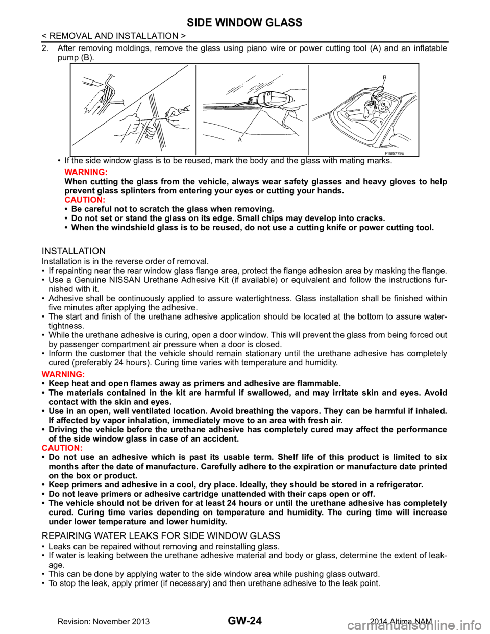
2. After removing moldings, remove the glass using piano wire or power cutting tool (A) and an inflatablepump (B).
• If the side window glass is to be reused, mark the body and the glass with mating marks. WARNING:
When cutting the glass from the vehicle, al ways wear safety glasses and heavy gloves to help
prevent glass splinters from entering your eyes or cutting your hands.
CAUTION:
• Be careful not to scratch the glass when removing.
• Do not set or stand the glass on its edge. Small chips may develop into cracks.
• When the windshield glass is to be reused, do not use a cutting knife or power cutting tool.
INSTALLATION
Installation is in the reverse order of removal.
• If repainting near the rear window glass flange area, protect the flange adhesion area by masking the flange.
• Use a Genuine NISSAN Urethane Adhesive Kit (if availabl e) or equivalent and follow the instructions fur-
nished with it.
• Adhesive shall be continuously applied to assure watert ightness. Glass installation shall be finished within
five minutes after applying the adhesive.
• The start and finish of the urethane adhesive application should be located at the bottom to assure water-
tightness.
• While the urethane adhesive is curing, open a door window . This will prevent the glass from being forced out
by passenger compartment air pressure when a door is closed.
• Inform the customer that the vehicle should rema in stationary until the urethane adhesive has completely
cured (preferably 24 hours). Curing time varies with temperature and humidity.
WARNING:
• Keep heat and open flames away as primers and adhesive are flammable.
• The materials contained in the kit are harmful if swallowed, and may irritate skin and eyes. Avoid
contact with the skin and eyes.
• Use in an open, well ventilated location. Avoid br eathing the vapors. They can be harmful if inhaled.
If affected by vapor inhalation, imme diately move to an area with fresh air.
• Driving the vehicle before the urethane adhesive has completely cured may affect the performance
of the side window gl ass in case of an accident.
CAUTION:
• Do not use an adhesive which is past its usable te rm. Shelf life of this product is limited to six
months after the date of manufacture. Carefully a dhere to the expiration or manufacture date printed
on the box or product.
• Keep primers and adhesive in a c ool, dry place. Ideally, they should be stored in a refrigerator.
• Do not leave primers or adhesive cartridge unattended with their caps open or off.
• The vehicle should not be driven for at least 24 hours or until the urethane adhesive has completely
cured. Curing time varies depe nding on temperature and humidity . The curing time will increase
under lower temperature and lower humidity.
REPAIRING WATER LEAKS FOR SIDE WINDOW GLASS
• Leaks can be repaired without removing and reinstalling glass.
• If water is leaking between the urethane adhesive material and body or glass, determine the extent of leak-
age.
• This can be done by applying water to the side window area while pushing glass outward.
• To stop the leak, apply primer (if necessary) and then urethane adhesive to the leak point.
PIIB5779E
Revision: November 20132014 Altima NAM
Page 2605 of 4801

REAR WINDOW GLASSGW-25
< REMOVAL AND INSTALLATION >
C
D E
F
G H
I
J
L
M A
B
GW
N
O P
REAR WINDOW GLASS
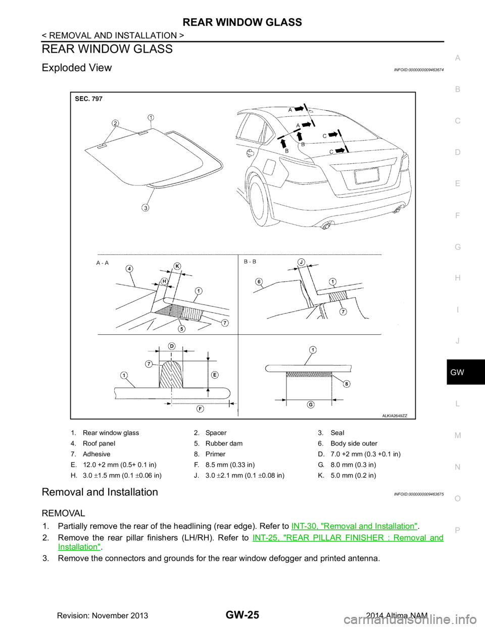
Exploded ViewINFOID:0000000009463674
Removal and InstallationINFOID:0000000009463675
REMOVAL
1. Partially remove the rear of the headlining (rear edge). Refer to INT-30, "Removal and Installation".
2. Remove the rear pillar finishers (LH/RH). Refer to INT-25, "REAR PILLAR FINISHER : Removal and
Installation".
3. Remove the connectors and grounds for the rear window defogger and printed antenna.
1. Rear window glass 2. Spacer 3. Seal
4. Roof panel 5. Rubber dam 6. Body side outer
7. Adhesive 8. Primer D. 7.0 +2 mm (0.3 +0.1 in)
E. 12.0 +2 mm (0.5+ 0.1 in) F. 8.5 mm (0.33 in) G. 8.0 mm (0.3 in)
H. 3.0 ±1.5 mm (0.1 ±0.06 in) J. 3.0 ±2.1 mm (0.1 ±0.08 in) K. 5.0 mm (0.2 in)
ALKIA2649ZZ
Revision: November 20132014 Altima NAM
Page 2606 of 4801

GW-26
< REMOVAL AND INSTALLATION >
REAR WINDOW GLASS
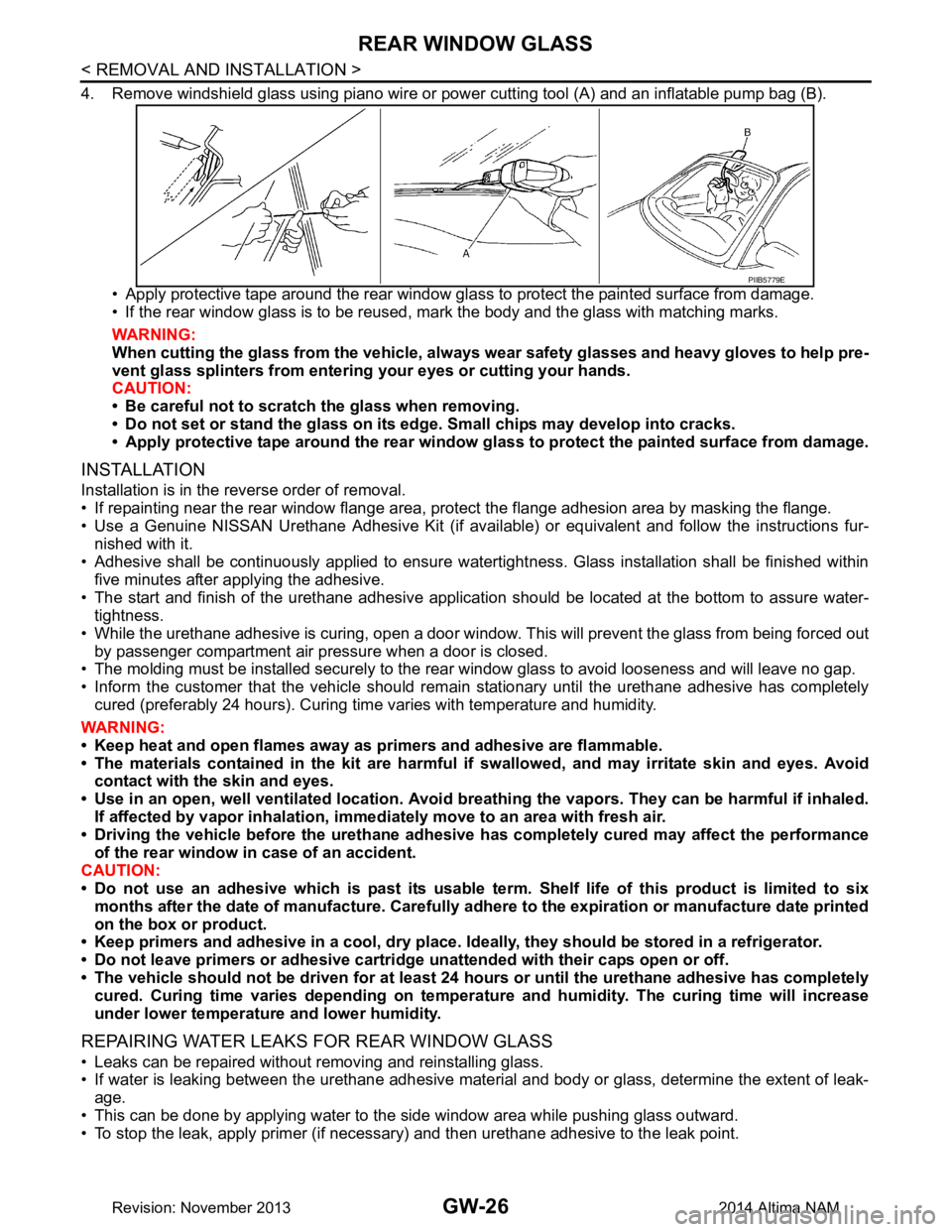
4. Remove windshield glass using piano wire or power cutting tool (A) and an inflatable pump bag (B).
• Apply protective tape around the rear window gla ss to protect the painted surface from damage.
• If the rear window glass is to be reused, mark the body and the glass with matching marks.
WARNING:
When cutting the glass from the vehicle, always wear safety glasses and heavy gloves to help pre-
vent glass splinters from entering your eyes or cutting your hands.
CAUTION:
• Be careful not to scratch the glass when removing.
• Do not set or stand the glass on its ed ge. Small chips may develop into cracks.
• Apply protective tape around th e rear window glass to protect the painted surface from damage.
INSTALLATION
Installation is in the reverse order of removal.
• If repainting near the rear window flange area, protect the flange adhesion area by masking the flange.
• Use a Genuine NISSAN Urethane Adhesive Kit (if availabl e) or equivalent and follow the instructions fur-
nished with it.
• Adhesive shall be continuously applied to ensure watert ightness. Glass installation shall be finished within
five minutes after applying the adhesive.
• The start and finish of the urethane adhesive application should be located at the bottom to assure water-
tightness.
• While the urethane adhesive is curing, open a door window . This will prevent the glass from being forced out
by passenger compartment air pressure when a door is closed.
• The molding must be installed securely to the rear window glass to avoid looseness and will leave no gap.
• Inform the customer that the vehicle should rema in stationary until the urethane adhesive has completely
cured (preferably 24 hours). Curing time varies with temperature and humidity.
WARNING:
• Keep heat and open flames away as primers and adhesive are flammable.
• The materials contained in the kit are harmful if swallowed, and may irritate skin and eyes. Avoid
contact with the skin and eyes.
• Use in an open, well ventilated location. Avoid br eathing the vapors. They can be harmful if inhaled.
If affected by vapor inhalation, imme diately move to an area with fresh air.
• Driving the vehicle before the urethane adhesive has completely cured may affect the performance
of the rear window in case of an accident.
CAUTION:
• Do not use an adhesive which is past its usable te rm. Shelf life of this product is limited to six
months after the date of manufacture. Carefully a dhere to the expiration or manufacture date printed
on the box or product.
• Keep primers and adhesive in a c ool, dry place. Ideally, they should be stored in a refrigerator.
• Do not leave primers or adhesive cartridge unattended with their caps open or off.
• The vehicle should not be driven for at least 24 hours or until the urethane adhesive has completely
cured. Curing time varies depe nding on temperature and humidity . The curing time will increase
under lower temperature and lower humidity.
REPAIRING WATER LEAKS FOR REAR WINDOW GLASS
• Leaks can be repaired without removing and reinstalling glass.
• If water is leaking between the urethane adhesive material and body or glass, determine the extent of leak-
age.
• This can be done by applying water to the side window area while pushing glass outward.
• To stop the leak, apply primer (if necessary) and then urethane adhesive to the leak point.
PIIB5779E
Revision: November 20132014 Altima NAM
Page 2670 of 4801
![NISSAN TEANA 2014 Service Manual
OPERATIONHAC-21
< SYSTEM DESCRIPTION > [AUTOMATIC AIR CONDITIONER]
C
D E
F
G H
J
K L
M A
B
HAC
N
O P
OPERATION
Switch Name and FunctionINFOID:0000000009463102
CONTROL OPERATION
A/C Switch Assembly NISSAN TEANA 2014 Service Manual
OPERATIONHAC-21
< SYSTEM DESCRIPTION > [AUTOMATIC AIR CONDITIONER]
C
D E
F
G H
J
K L
M A
B
HAC
N
O P
OPERATION
Switch Name and FunctionINFOID:0000000009463102
CONTROL OPERATION
A/C Switch Assembly](/manual-img/5/57390/w960_57390-2669.png)
OPERATIONHAC-21
< SYSTEM DESCRIPTION > [AUTOMATIC AIR CONDITIONER]
C
D E
F
G H
J
K L
M A
B
HAC
N
O P
OPERATION
Switch Name and FunctionINFOID:0000000009463102
CONTROL OPERATION
A/C Switch Assembly
Switch Operation
1. Defroster switch 2. Rear window defogger switch 3. Temperature control dial (driver side)
4. ON/OFF switch 5. Fan control switch 6. Mode switch
7. A/C switch 8. Temperature control dial (passen- ger side)9. Recirculation switch
10. Fresh air switch 11. DUAL switch 12. Display
13. AUTO switch
ALIIA0603ZZ
Revision: November 20132014 Altima NAMRevision: November 20132014 Altima NAM
Page 2702 of 4801
![NISSAN TEANA 2014 Service Manual
CONFIGURATION (HVAC)HAC-53
< BASIC INSPECTION > [AUTOMATIC AIR CONDITIONER]
C
D E
F
G H
J
K L
M A
B
HAC
N
O P
CONFIGURATION (HVAC)
DescriptionINFOID:0000000009463118
Vehicle specification needs to NISSAN TEANA 2014 Service Manual
CONFIGURATION (HVAC)HAC-53
< BASIC INSPECTION > [AUTOMATIC AIR CONDITIONER]
C
D E
F
G H
J
K L
M A
B
HAC
N
O P
CONFIGURATION (HVAC)
DescriptionINFOID:0000000009463118
Vehicle specification needs to](/manual-img/5/57390/w960_57390-2701.png)
CONFIGURATION (HVAC)HAC-53
< BASIC INSPECTION > [AUTOMATIC AIR CONDITIONER]
C
D E
F
G H
J
K L
M A
B
HAC
N
O P
CONFIGURATION (HVAC)
DescriptionINFOID:0000000009463118
Vehicle specification needs to be written with CONSULT because it is not written after replacing A/C auto amp.
Configuration has three functions as follows:
CAUTION:
• When replacing A/C auto amp., you must perform “Select Saved Data List” or "After Replace ECU"
with CONSULT.
• Complete the procedure of “Select Saved Da ta List” or "After Replace ECU" in order.
• If you set incorrect “Select Saved Data List” or "After Replace ECU", incidents might occur.
• Configuration is different for each vehicle model. Confirm conf iguration of each vehicle model.
• Never perform “Select Saved Data List” or "A fter Replace ECU" except for new A/C auto amp.
Work ProcedureINFOID:0000000009463119
1.WRITING MODE SELECTION
CONSULT
Select “Reprogramming, Configuration” of A/C auto amp.
When writing saved data>>GO TO 2.
When writing manually>>GO TO 3.
2.PERFORM “SAVED DATA LIST”
CONSULT
Automatically “Operation Log Selection” window will disp lay if “Before Replace ECU” was performed. Select
applicable file from the “Saved Data List” and press “Confirm”.
>> Work End.
3.PERFORM “AFTER REPLACE ECU” OR “MANUAL CONFIGURATION”
CONSULT
1. Select “After Replace ECU” or “Manual Configuration”.
2. Identify the correct model and configuration list. Refer to HAC-54, "Configuration List"
.
3. Confirm and/or change setting value for each item.
CAUTION:
Thoroughly read and understand the vehicle speci fication. ECU control may not operate normally
if the setting is not correct.
4. Select “Next”. CAUTION:
Make sure to select “Next”, confirm each setting value and press “OK” even if the indicated con-
figuration of brand new A/C auto am p. is same as the desirable configuration. If not, configuration
which is set automatically by selecti ng vehicle model cannot be memorized.
5. When "Completed", select "End".
>> GO TO 4.
4.OPERATION CHECK
Confirm that each function controlled by A/C auto amp. operates normally.
Function Description
"Before Replace ECU" • Reads the vehicle configuration of current A/C auto amp.
• Saves the read vehicle configuration.
"After Replace ECU" Writes the vehicle configuration with manual selection.
"Select Saved Data List" Writes the vehicle configuration with saved data.
Revision: November 20132014 Altima NAMRevision: November 20132014 Altima NAM
Page 2773 of 4801
![NISSAN TEANA 2014 Service Manual
HAC-124
< SYSTEM DESCRIPTION >[MANUAL AIR CONDITIONER]
DIAGNOSIS SYSTEM (BCM)
DIAGNOSIS SYSTEM (BCM)
CONSULT Function (BCM - COMMON ITEM)INFOID:0000000009958322
CAUTION:
After disconnecting the CONS NISSAN TEANA 2014 Service Manual
HAC-124
< SYSTEM DESCRIPTION >[MANUAL AIR CONDITIONER]
DIAGNOSIS SYSTEM (BCM)
DIAGNOSIS SYSTEM (BCM)
CONSULT Function (BCM - COMMON ITEM)INFOID:0000000009958322
CAUTION:
After disconnecting the CONS](/manual-img/5/57390/w960_57390-2772.png)
HAC-124
< SYSTEM DESCRIPTION >[MANUAL AIR CONDITIONER]
DIAGNOSIS SYSTEM (BCM)
DIAGNOSIS SYSTEM (BCM)
CONSULT Function (BCM - COMMON ITEM)INFOID:0000000009958322
CAUTION:
After disconnecting the CONSULT vehicle interface (VI) from the data link connector, the ignition must
be cycled OFF → ON (for at least 5 seconds) → OFF. If this step is not performed, the BCM may not go
to ”sleep mode”, potentially causing a di scharged battery and a no-start condition.
APPLICATION ITEM
CONSULT performs the following functions via CAN communication with BCM.
SYSTEM APPLICATION
BCM can perform the following functions.
Direct Diagnostic Mode Description
Ecu Identification The BCM part number is displayed.
Self Diagnostic Result The BCM self diagnostic results are displayed.
Data Monitor The BCM input/output data is displayed in real time.
Active Test The BCM activates outputs to test components.
Work support The settings for BCM functions can be changed.
Configuration • The vehicle specification can be read and saved.
• The vehicle specification can be written when replacing BCM.
CAN Diag Support Mntr The result of transmit/receive diagnosis of CAN communication is displayed.
System Sub System Direct Diagnostic Mode
Ecu Identification
Self Diagnostic Result
Data Monitor
Active Test
Work support
Configuration
CAN Diag Support Mntr
Door lock DOOR LOCK ××××
Rear window defogger REAR DEFOGGER ×××
Warning chime BUZZER ××
Interior room lamp timer INT LAMP ×××
Remote keyless entry system MULTI REMOTE ENT ×××
Exterior lamp HEADLAMP ×××
Wiper and washer WIPER ×××
Turn signal and hazard warning lamps FLASHER ××
Air conditioner AIR CONDITIONER ×
Intelligent Key system INTELLIGENT KEY ××××
Combination switch COMB SW ×
BCM BCM × × ×××
Immobilizer IMMU ×××
Interior room lamp battery saver BATTERY SAVER ××
Trunk open TRUNK ×
Vehicle security system THEFT ALM ×××
RAP system RETAINED PWR ×
Revision: November 20132014 Altima NAMRevision: November 20132014 Altima NAM
Page 2826 of 4801

COMPONENT PARTSINL-5
< SYSTEM DESCRIPTION >
C
D E
F
G H
I
J
K
M A
B
INL
N
O P
SYSTEM DESCRIPTION
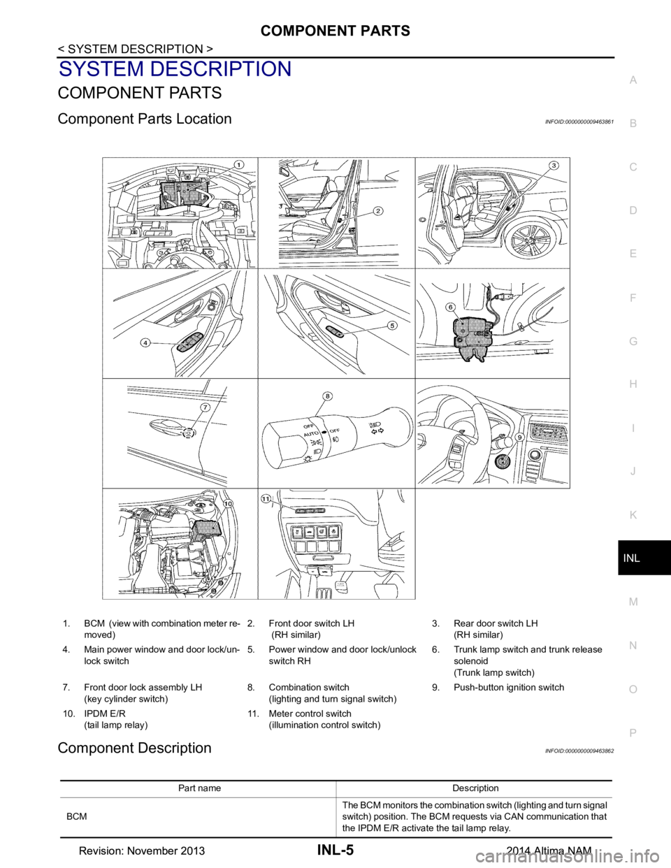
COMPONENT PARTS
Component Parts LocationINFOID:0000000009463861
Component DescriptionINFOID:0000000009463862
1. BCM (view with combination meter re- moved) 2. Front door switch LH
(RH similar) 3. Rear door switch LH
(RH similar)
4. Main power window and door lock/un- lock switch 5. Power window and door lock/unlock
switch RH 6. Trunk lamp switch and trunk release
solenoid
(Trunk lamp switch)
7. Front door lock assembly LH (key cylinder switch) 8. Combination switch
(lighting and turn signal switch) 9. Push-button ignition switch
10. IPDM E/R (tail lamp relay) 11. Meter control switch
(illumination control switch)
Part name Description
BCM The BCM monitors the combination switch (lighting and turn signal
switch) position. The BCM requests via CAN communication that
the IPDM E/R activate the tail lamp relay.
Revision: November 20132014 Altima NAMRevision: November 20132014 Altima NAM
Page 2827 of 4801

INL-6
< SYSTEM DESCRIPTION >
COMPONENT PARTS
IPDM E/RThe IPDM E/R activates the tail lamp relay based on inputs re-
ceived from the BCM via the CAN communication.
Push button ignition switch Provides ignition switch status to the BCM.
Door switches Provides door OPEN/CLOSED status to the BCM.
Combination switch
(lighting and turn signal switch) The combination switch (lighting and turn signal switch) provides
input to the BCM. The BCM then sends a tail lamp relay request
signal to the IPDM E/R via CAN communication to operate the il-
lumination system.
Trunk lamp switch and release solenoid
(trunk lamp switch) Provides trunk lamp switch OP
EN/CLOSED status to the BCM.
Power window and door lock/unlock switch RH Provides door lock/unlock position switch RH status to the BCM.
Main power window and door lock/unlock switch Provides door lock/unlock position switch LH status to the BCM.
Meter control switch
(illumination control switch) • Adjusts the illumination system and combination meter illumina-
tion brightness (with multiple illumination control).
• Only adjusts the combination meter illumination brightness
(with meter illumination control only).
Front door lock assembly LH (key cylinder switch) Provides front door lock assembly LH (key cylinder switch) door
lock/unlock switch position status to the BCM.
Revision: November 20132014 Altima NAMRevision: November 20132014 Altima NAM