Page 2595 of 4801
FRONT DOOR GLASSGW-15
< REMOVAL AND INSTALLATION >
C
D E
F
G H
I
J
L
M A
B
GW
N
O P
Installation is in the reverse order of removal.
• Tighten the front door regulator to glass bolts to specification.
FRONT DOOR GLASS INSPECTION AFTER INSTALLATION
• Check that the door glass is securely set into the glass run groove.
• Lower the door glass slightly [approximately 10 to 20 mm (0.4 to 0.8 in)] and check that the clearance to the
sash is parallel. If the clearance between the door gla ss and sash is not parallel, loosen the regulator bolts,
guide rail bolts, and door glass and guide rail bolts to correct the glass position.
Inspection and AdjustmentINFOID:0000000009463663
SYSTEM INITIALIZATION (IF NECESSARY)
• If any of the following occur, syst em initialization must be performed.
- Electric power supply to power window switch or motor is interrupted by blown fuse or disconnecting battery cable, etc.
- Removal and installation of the regulator assembly.
- Removal and installation of the motor from the regulator assembly.
- Removal and installation of the harness connector of the power window switch.
- Operation of the regulator assembly as a unit.
- Removal and installation of the door glass.
- Removal and installation of the door glass run.
- Window is partly opened and or closed multiple times with out being fully closed.
• To perform system initialization, refer to the following:
- For LH ONLY ANTI-PINCH, refer to PWC-27, "ADDITIONAL SERVICE WHEN REMOVING BATTERY
NEGATIVE TERMINAL : Special Repair Requirement".
- For LH&RH FRONT ANTI-PINCH, refer to PWC-93, "ADDITIONAL SERVICE WHEN REMOVING BAT-
TERY NEGATIVE TERMINAL : Special Repair Requirement".
INSPECT THE FUNCTION OF THE ANTI-PINCH SYSTEM.
To inspect the anti-pinch system, refer to the following:
• For LH ONLY ANTI-PINCH, refer to PWC-27, "ADDITIONAL SERVICE WHEN REMOVING BATTERY
NEGATIVE TERMINAL : Special Repair Requirement".
• For LH&RH FRONT ANTI-PINCH, refer to PWC-93, "ADDITIONAL SERVICE WHEN REMOVING BAT-
TERY NEGATIVE TERMINAL : Special Repair Requirement".
Front door regulator to glass bol
ts : 6.1 N·m (0.62 kg-m, 54 in-lb)
Revision: November 20132014 Altima NAM
Page 2596 of 4801
GW-16
< REMOVAL AND INSTALLATION >
FRONT REGULATOR
FRONT REGULATOR
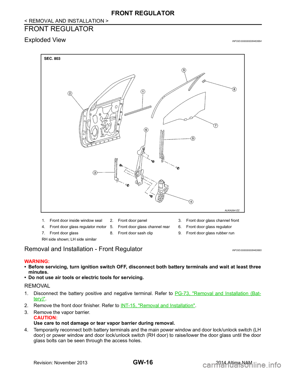
Exploded ViewINFOID:0000000009463664
Removal and Installation - Front RegulatorINFOID:0000000009463665
WARNING:
• Before servicing, turn ignition sw itch OFF, disconnect both battery terminals and wait at least three
minutes.
• Do not use air tools or el ectric tools for servicing.
REMOVAL
1. Disconnect the battery positive and negative terminal. Refer to PG-73, "Removal and Installation (Bat-
tery)".
2. Remove the front door finisher. Refer to INT-15, "Removal and Installation"
.
3. Remove the vapor barrier. CAUTION:
Use care to not damage or tear vapor barrier during removal.
4. Temporarily reconnect both battery terminals and the main power window and door lock/unlock switch (LH door) or power window and door lock/unlock switch ( RH door) to raise/lower the door glass until the door
glass bolts can be seen through the access holes.
1. Front door inside window seal 2. Front door panel 3. Front door glass channel front
4. Front door glass regulator motor 5. Front door glass channel rear 6. Front door glass regulator
7. Front door glass 8. Front door sash clip 9. Front door glass rubber run
RH side shown; LH side similar
ALKIA2641ZZ
Revision: November 20132014 Altima NAM
Page 2598 of 4801
GW-18
< REMOVAL AND INSTALLATION >
FRONT REGULATOR
Inspection and Adjustment
INFOID:0000000009463666
SYSTEM INITIALIZATION (IF NECESSARY)
• If any of the following occur, sy stem initialization must be performed.
- Electric power supply to power window switch or moto r is interrupted by blown fuse or disconnecting battery
cable, etc.
- Removal and installation of the regulator assembly.
- Removal and installation of the motor from the regulator assembly.
- Removal and installation of the harness connector of the power window switch.
- Operation of the regulator assembly as a unit.
- Removal and installation of the door glass.
- Removal and installation of the door glass run.
- Window is partly opened and or closed multiple times with out being fully closed.
• To perform system initialization, refer to the following:
- For LH ONLY ANTI-PINCH, refer to PWC-27, "ADDITIONAL SERVICE WHEN REMOVING BATTERY
NEGATIVE TERMINAL : Special Repair Requirement".
- For LH&RH FRONT ANTI-PINCH, refer to PWC-93, "ADDITIONAL SERVICE WHEN REMOVING BAT-
TERY NEGATIVE TERMINAL : Special Repair Requirement".
INSPECT THE FUNCTION OF THE ANTI-PINCH SYSTEM.
To inspect the anti-pinch system, refer to the following:
• For LH ONLY ANTI-PINCH, refer to PWC-27, "ADDITIONAL SERVICE WHEN REMOVING BATTERY
NEGATIVE TERMINAL : Special Repair Requirement".
• For LH&RH FRONT ANTI-PINCH, refer to PWC-93, "ADDITIONAL SERVICE WHEN REMOVING BAT-
TERY NEGATIVE TERMINAL : Special Repair Requirement".
Removal and Installation - Front Power Window MotorINFOID:0000000009463667
REMOVAL
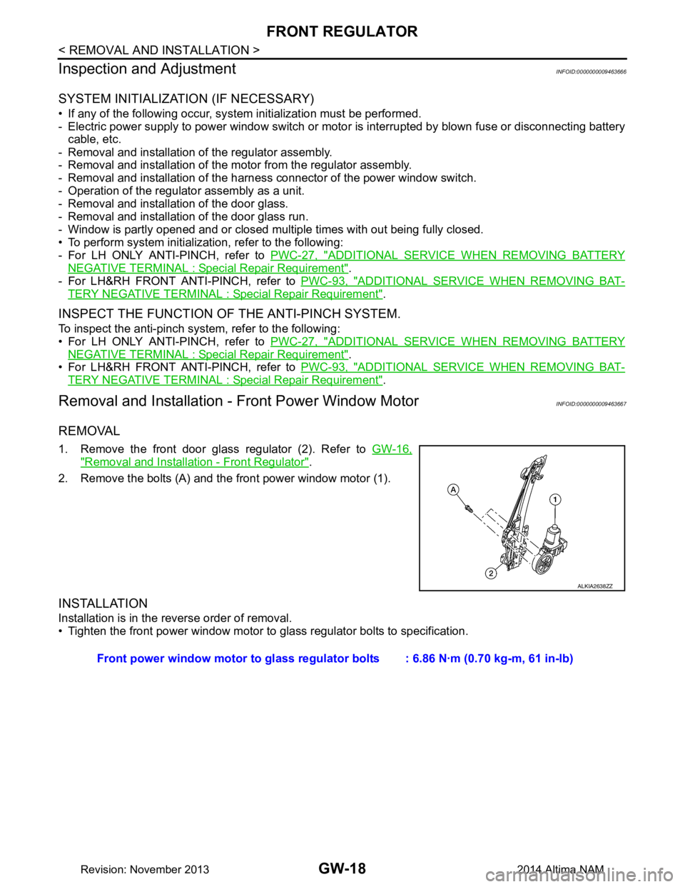
1. Remove the front door glass regulator (2). Refer to GW-16,
"Removal and Installation - Front Regulator".
2. Remove the bolts (A) and the front power window motor (1).
INSTALLATION
Installation is in the reverse order of removal.
• Tighten the front power window motor to glass regulator bolts to specification.
ALKIA2638ZZ
Front power window motor to glass regulator bolts : 6.86 N·m (0.70 kg-m, 61 in-lb)
Revision: November 20132014 Altima NAM
Page 2599 of 4801
REAR DOOR GLASSGW-19
< REMOVAL AND INSTALLATION >
C
D E
F
G H
I
J
L
M A
B
GW
N
O P
REAR DOOR GLASS
Removal and InstallationINFOID:0000000009463668
REMOVAL
1. Remove the rear door finisher. Refer to INT-18, "Removal and Installation".
2. Remove the vapor barrier. CAUTION:
Use care to not damage or tear vapor barrier during removal.
3. Remove the rear door window inside seal.
4. Remove the rear door window run rubber.
5. Remove bolts (A) and rear door glass rear run channel (1).
6. Temporarily reconnect the rear power window switch to raise/ lower the rear door glass until the rear door regulator to glass
bolts (A) can be seen through the access holes.
7. Remove the rear door glass to regulator bolts (A). CAUTION:
When removing the door regula tor to glass bolts be sure to
secure glass to prevent it from falling.
8. Remove the door glass.
INSTALLATION
Installation is in the reverse order of removal.
• After installation inspect and adjust as necessary.
• Tighten the rear door regulator to glass bolts to specification.
REAR DOOR GLASS INSPECTION AFTER INSTALLATION
• Check that the door glass is securely set into the glass run groove.
• Lower the glass slightly [approx. 10 to 20 mm (0.4 to 0.8 in)], and make sure the clearance to the sash is par-
allel. If the clearance between the glass and sash is not parallel, loosen the regulator mounting bolts, guide
rail mounting bolts, and glass and carrier plate mounting bolts to correct the glass position.
ALKIA2636ZZ
ALKIA2635ZZ
Rear door regulator to glass bolts : 7.0 N·m (0.7 kg-m, 62 in-lb)
Revision: November 20132014 Altima NAM
Page 2600 of 4801
GW-20
< REMOVAL AND INSTALLATION >
REAR REGULATOR
REAR REGULATOR
Exploded ViewINFOID:0000000009463669
Removal and Installation - Rear RegulatorINFOID:0000000009463670
NOTE:
RH side shown; LH side similar
REMOVAL
1. Remove the rear door finisher. Refer to INT-18, "Removal and Installation".
2. Remove the vapor barrier. CAUTION:
Use care to not damage or tear vapor barrier during removal.
1. Rear door panel 2. Rear door glass regulator motor 3. Rear door glass regulator
4. Rear door glass 5. Rear door sash clip 6. Rear door inside window seal
7. Rear door glass rubber run 8. Rear door glass rear run channel
ALKIA2643ZZ
Revision: November 20132014 Altima NAM
Page 2601 of 4801
REAR REGULATORGW-21
< REMOVAL AND INSTALLATION >
C
D E
F
G H
I
J
L
M A
B
GW
N
O P
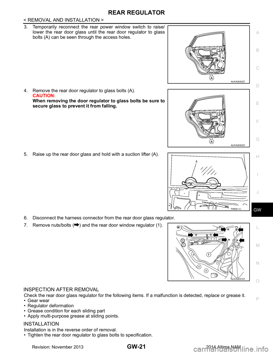
3. Temporarily reconnect the rear power window switch to raise/ lower the rear door glass until the rear door regulator to glass
bolts (A) can be seen through the access holes.
4. Remove the rear door regulator to glass bolts (A). CAUTION:
When removing the door regula tor to glass bolts be sure to
secure glass to prevent it from falling.
5. Raise up the rear door glass and hold with a suction lifter (A).
6. Disconnect the harness connector from the rear door glass regulator.
7. Remove nuts/bolts ( ) and the rear door window regulator (1).
INSPECTION AFTER REMOVAL
Check the rear door glass regul ator for the following items. If a malf unction is detected, replace or grease it.
• Gear wear
• Regulator deformation
• Grease condition for each sliding part
• Apply multi-purpose grease at sliding points.
INSTALLATION
Installation is in the reverse order of removal.
• Tighten the rear door regulator to glass bolts to specification.
ALKIA2635ZZ
ALKIA2635ZZ
PIIB3511J
ALKIA2637ZZ
Revision: November 20132014 Altima NAM
Page 2602 of 4801
GW-22
< REMOVAL AND INSTALLATION >
REAR REGULATOR
Removal and Installation - Rear Power Window Motor
INFOID:0000000009463671
REMOVAL
1. Remove the rear door glass regulator (1). Refer to GW-20,
"Removal and Installation - Rear Regulator"
2. Remove the bolts and the rear power window motor (2).
INSTALLATION
Installation is in the reverse order of removal.
• Tighten the rear power window motor to glass regulator bolts to specification. Rear door regulator to glass bolts : 7.0 N·m (0.7 kg-m, 62 in-lb)
ALKIA2640ZZ
Rear power window motor to glass regulat
or bolts : 6.86 N·m (0.70 kg-m, 61 in-lb)
Revision: November 20132014 Altima NAM
Page 2603 of 4801
SIDE WINDOW GLASSGW-23
< REMOVAL AND INSTALLATION >
C
D E
F
G H
I
J
L
M A
B
GW
N
O P
SIDE WINDOW GLASS
ComponentsINFOID:0000000009463672
Removal and InstallationINFOID:0000000009463673
REMOVAL
1. Remove the rear pillar finisher. Refer to INT-25, "REAR PILLAR FINISHER : Removal and Installation".
ALKIA2646ZZ
1. Side window glass 2. Spacer 3. Rear pillar finisher
4. Rear body pillar 5. Seal A. Primer
B. Adhesive C. 7 mm (0.3 in) D. 12 mm (0.5 in)
E. 20 mm (0.8 in)
Revision: November 20132014 Altima NAM