2011 SKODA OCTAVIA TOUR Owner's Manual
-
 1
1 -
 2
2 -
 3
3 -
 4
4 -
 5
5 -
 6
6 -
 7
7 -
 8
8 -
 9
9 -
 10
10 -
 11
11 -
 12
12 -
 13
13 -
 14
14 -
 15
15 -
 16
16 -
 17
17 -
 18
18 -
 19
19 -
 20
20 -
 21
21 -
 22
22 -
 23
23 -
 24
24 -
 25
25 -
 26
26 -
 27
27 -
 28
28 -
 29
29 -
 30
30 -
 31
31 -
 32
32 -
 33
33 -
 34
34 -
 35
35 -
 36
36 -
 37
37 -
 38
38 -
 39
39 -
 40
40 -
 41
41 -
 42
42 -
 43
43 -
 44
44 -
 45
45 -
 46
46 -
 47
47 -
 48
48 -
 49
49 -
 50
50 -
 51
51 -
 52
52 -
 53
53 -
 54
54 -
 55
55 -
 56
56 -
 57
57 -
 58
58 -
 59
59 -
 60
60 -
 61
61 -
 62
62 -
 63
63 -
 64
64 -
 65
65 -
 66
66 -
 67
67 -
 68
68 -
 69
69 -
 70
70 -
 71
71 -
 72
72 -
 73
73 -
 74
74 -
 75
75 -
 76
76 -
 77
77 -
 78
78 -
 79
79 -
 80
80 -
 81
81 -
 82
82 -
 83
83 -
 84
84 -
 85
85 -
 86
86 -
 87
87 -
 88
88 -
 89
89 -
 90
90 -
 91
91 -
 92
92 -
 93
93 -
 94
94 -
 95
95 -
 96
96 -
 97
97 -
 98
98 -
 99
99 -
 100
100 -
 101
101 -
 102
102 -
 103
103 -
 104
104 -
 105
105 -
 106
106 -
 107
107 -
 108
108 -
 109
109 -
 110
110 -
 111
111 -
 112
112 -
 113
113 -
 114
114 -
 115
115 -
 116
116 -
 117
117 -
 118
118 -
 119
119 -
 120
120 -
 121
121 -
 122
122 -
 123
123 -
 124
124 -
 125
125 -
 126
126 -
 127
127 -
 128
128 -
 129
129 -
 130
130 -
 131
131 -
 132
132 -
 133
133 -
 134
134 -
 135
135 -
 136
136 -
 137
137 -
 138
138 -
 139
139 -
 140
140 -
 141
141 -
 142
142 -
 143
143 -
 144
144 -
 145
145 -
 146
146 -
 147
147 -
 148
148 -
 149
149 -
 150
150 -
 151
151 -
 152
152 -
 153
153 -
 154
154 -
 155
155 -
 156
156 -
 157
157 -
 158
158 -
 159
159 -
 160
160 -
 161
161 -
 162
162 -
 163
163 -
 164
164 -
 165
165 -
 166
166 -
 167
167 -
 168
168 -
 169
169 -
 170
170 -
 171
171 -
 172
172 -
 173
173 -
 174
174 -
 175
175 -
 176
176 -
 177
177 -
 178
178 -
 179
179 -
 180
180 -
 181
181 -
 182
182
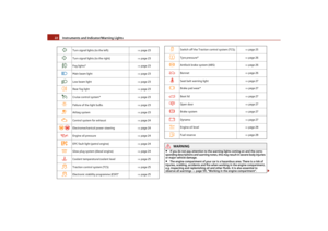
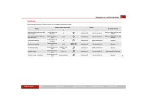
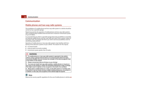
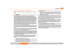
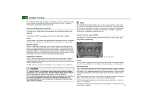
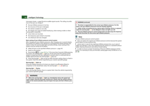
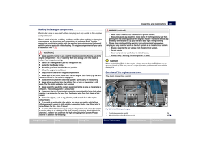
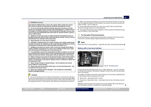
 Owners Manual Cockpit
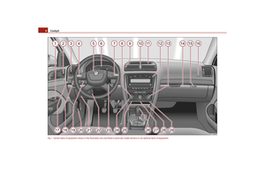
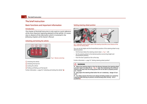
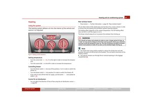
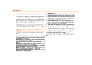
8Fig. 1 Certain items of equipment shown in the illustration are on ly fitted to particular model versions or are optional items of equipment.s2lk.2.book Page 8 Monday, April 18, 2011 7:4")
 Owners Manual Cockpit9
Using the system
Safety
Driving Tips
General Maintenance
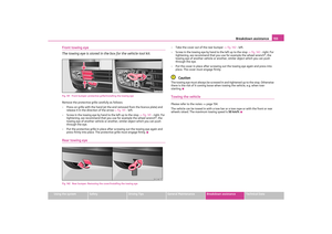
Breakdown assistance
Technical Data
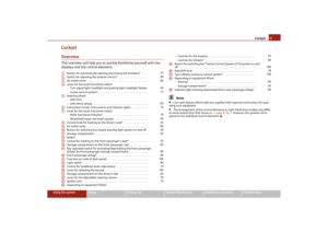
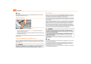
CockpitOverviewThis overview will help you to quickly familiarise yourself with the
displays and")
 Owners Manual The brief instruction
10
The brief instructionBasic functions and important informationIntroduction
The chapter of the brief instruction is only used as a quick reference
of the most important operat")
 Owners Manual The brief instruction11
Using the system
Safety
Driving Tips
General Maintenance
Breakdown assistance
Technical Data
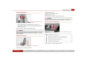
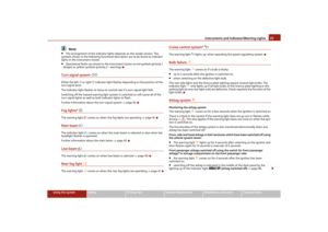
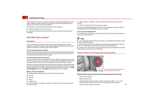
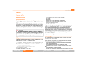
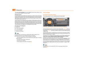
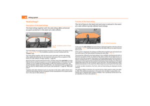
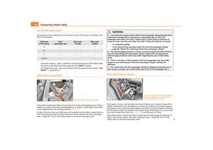
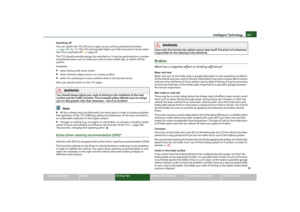
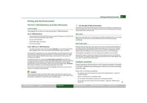
Seat belt height adjuster– Move the height adjuster in the desired direction up o")
 Owners Manual The brief instruction
12
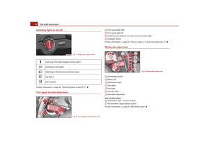
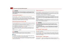
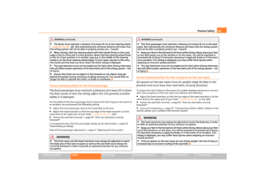
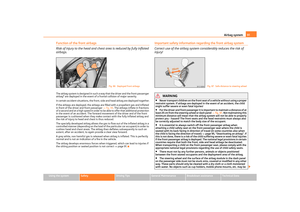
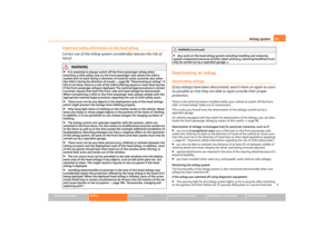
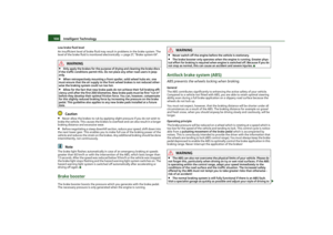
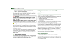
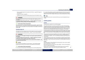
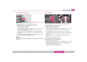
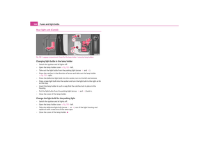
Switching lights on and offFurther information page 40, “Switching lights on and off ”.Turn signal and main beam lever
Turn signal light right
Turn signal light")
 Owners Manual The brief instruction13
Using the system
Safety
Driving Tips
General Maintenance
Breakdown assistance
Technical Data
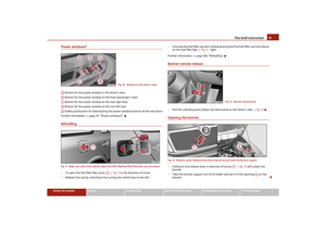
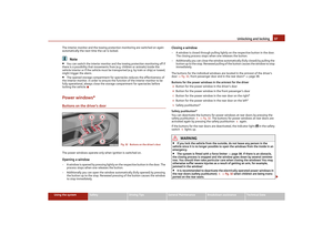
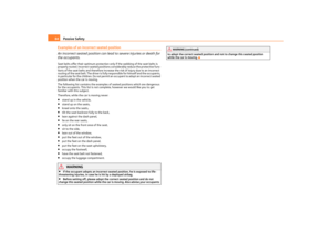
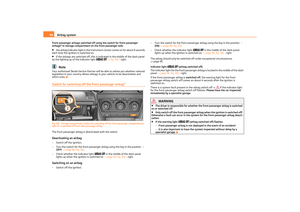
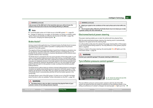
Power windows* Button for the power window in the drivers door
Button for the pow")
 Owners Manual The brief instruction
14
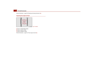
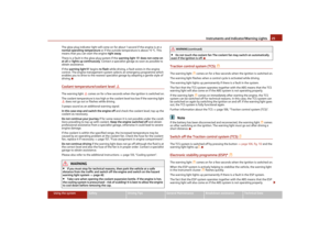
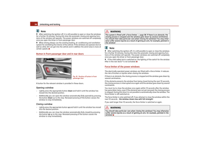
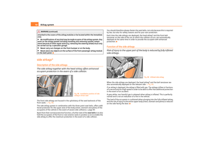
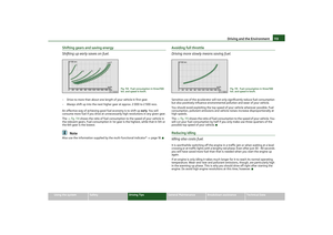
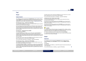
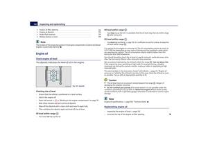
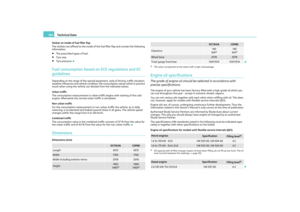
Further information page 130, “Opening and closing the bonnet.”.Inspecting the engine oil level Engine oil must not be refilled.
Engine oil can be refilled.
Engin")
 Owners Manual Instruments and Indicator/Warning Lights15
Using the system
Safety
Driving Tips
General Maintenance
Breakdown assistance
Technical Data
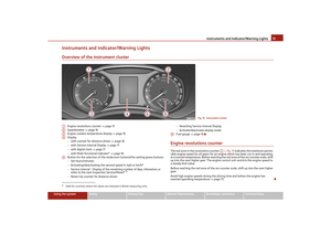
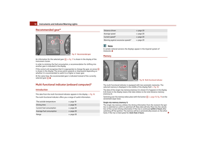
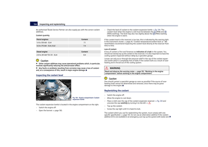
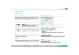
Instruments and Indicator/Warning LightsOverview of the instrume")