Page 153 of 183
 Owners Manual Breakdown assistance
152
Raise vehicle
You have to raise the vehicle with the lifting jack* in order to be able
to take off the wheel.Position the lifting jack* by selecting the jacking point which i")
Breakdown assistance
152
Raise vehicle
You have to raise the vehicle with the lifting jack* in order to be able
to take off the wheel.Position the lifting jack* by selecting the jacking point which is closest to the wheel
to be removed fig. 138 . The jacking point is located directly below the engraving
in the lower sill. The engraving is only visible after opening the door.
– Position the lifting jack* below the jacking point and move it up until its claw is positioned directly below the vertical web of the lower sill.
– Align the* lifting jack* so that its claw grasps the web of the lower sill and the base plate is resting flat on the floor.
– Turn the lifting jack* up further until the wheel is just clear of the ground.
Ground which is soft and slippery below the base plate of the lifting jack* can cause
the vehicle to slip off the lifting jack*. It is therefore always necessary to place the
lifting jack* on a solid surface or use a wide and stable base. Use a non-slip base (e.g.
a rubber foot mat) if the surface is smooth, such as cobbled stones, a tiled floor, etc.
WARNING
•
Always raise the vehicle with the doors closed - risk of injury!
•
Take suitable measures to prevent the base of the lifting jack* from slipping
off - risk of injury!
•
Not positioning the lifting jack* at the specified points can result in damage
to the vehicle. The jack can also slip off if it does not have sufficient grip - risk of
injury!
•
It is important to support the vehicle wi th suitable supporting blocks if you
wish to work under the lifted vehicle - risk of injury!
Securing wheels against being stolen*
You need a special adapter for slackening the safety wheel bolts.– Pull off the full wheel trim/cap from the wheel hub or cap from the safety wheel bolt.
– Insert the adapter with its toothed side fully into the inner toothing of the safety wheel bolt right down in such a way that only the outer hexagon is
jutting out fig. 139 .
– Insert the wheel wrench* fully onto the adapter .
– Slacken the wheel bolt, or tighten it firmly page 151.
– Reinstall the full wheel trim/wheel cap after removing the adapter or place the cap onto the safety wheel bolt.
–Have the tightening torque checked with a torque wrench as soon as possible.
Steel and light alloy wheels must be ti ghtened to a tightening torque of 120 Nm.
The safety wheel bolts on vehicles fitted with them (one safety wheel bolt per
wheel) can only be loosened or tighten up by using the adapter provided.
It is meaningful to note the code numb er hammered into the rear side of the
adapter or the rear side of the safety wheel bolts. You can obtain a replacement
adapter from an authorised Škoda Service Partner, if necessary, by quoting this
number.
We recommend that you always carry the adapter for the wheel bolts with you in
the vehicle. It should be stowed in the vehicle tool kit.
Caution
Damage can occur to the adapter and safety wheel bolt if the safety wheel bolt is
tightened up too much.
Fig. 138 Changing a wheel: Jacking
points for positioning lifting jack
A
B
Fig. 139 Safety wheel bolt with adapter
BA
B
s2lk.2.book Page 152 Monday, April 18, 2011 7:41 AM
Page 154 of 183
 Owners Manual Breakdown assistance153
Using the system
Safety
Driving Tips
General Maintenance
Breakdown assistance
Technical Data
Note
The set of safety wheel bolts can be obta ined from an authorised Škoda Servi")
Breakdown assistance153
Using the system
Safety
Driving Tips
General Maintenance
Breakdown assistance
Technical Data
Note
The set of safety wheel bolts can be obta ined from an authorised Škoda Service
Partner.Jump-startingInitial stepsYou can use the battery of another vehicl e for jump-starting yours if the engine
does not start because the battery on your ve hicle is flat. You will require jump-start
cables for this purpose.
Both batteries must have a rated voltage of 12 V. The capacity (Ah) of the battery
supplying the power must not be signific antly less than the capacity of the
discharged battery in your vehicle.
Jump-start cables
Only use jump-start cables which have an adequately large cross-section and insu-
lated terminal clamps. Please pay attent ion to the manufacturer's instructions.
Positive cable - colour coding in the majority of cases red.
Negative cable - colour coding in the majority of cases black.
WARNING
•
A discharged battery may already freeze at temperatures just below 0 °C. In
case of frozen battery carry out no jump-starting - risk of explosion!
•
Please pay attention to the warning instructions relating to working in the
engine compartment page 131, “Working in the engine compartment”.Note
•
There must not be any contact between the two vehicles otherwise current may
flow as soon as the negati ve terminals are connected.
•
The discharged battery must be properly connected to the system of the
vehicle.
•
Switch off any mobile phone, pay attention to the instructions for use of the
mobile phone in such a situation.
•
We recommend you buy jump-start cables from a car battery specialist.
Start engineIt is important to connect the jump -start cables in the correct order.Connecting positive terminals– Attach one end to the positive terminal fig. 140 of the discharged battery
.
– Attach the other end to the positive terminal of the battery supplying the
power .Connecting negative terminal and engine block– Attach one end to the negative termin al of the battery supplying the power
.
– Attach the other end to a solid metal part which is connected firmly to the engine block, or to the engine block itself.Starting the engine– Start the engine of the vehicle providing current and run the engine at idling
speed.
– Now start the engine of the vehicle with the discharged battery.
– Interrupt the attempt at starting an engine after 10 seconds if it does not start right away and wait for about 30 seconds before repeating the attempt.
– Disconnect the cables on the engine in exactly the reverse order they were
connected up.
Fig. 140 Jump-starting using the battery
from another vehicle: A - flat vehicle
battery, B - battery providing current
1
A
2
B
3
B
4
s2lk.2.book Page 153 Monday, April 18, 2011 7:41 AM
Page 155 of 183
 Owners Manual Breakdown assistance
154WARNING
•
The non-insulated parts of the termi nal clamps must never make contact
with each other. Furthermore, the cable connected to the positive terminal of
the battery")
Breakdown assistance
154WARNING
•
The non-insulated parts of the termi nal clamps must never make contact
with each other. Furthermore, the cable connected to the positive terminal of
the battery must not come into contact with electrically conducting parts of the
vehicle - risk of a short circuit!
•
Do not affix the jump starting cables to the negative terminal of the
discharged battery. There is the risk of detonating gas seeping out the battery
being ignited by the strong spark which results from the engine being started.
•
Run the jump-start cables so that they cannot be caught by any rotating
parts in the engine compartment.
•
Do not bend over the batteries - risk of caustic burns!
•
The vent screws of the battery cells must be tightened firmly.
•
Keep any sources of ignition (naked fl ame, smouldering cigarettes etc.) away
from the battery - risk of an explosion!
•
Never jump-start the batteries which have a too low electrolyte level - risk
of explosion and caustic burns!
Tow-starting and towing vehicleGeneralPlease pay attention to the following instru ctions if you are going to use a tow rope:Driver of the towing vehicle– Do not drive off until the tow rope is taught.
– Release the clutch particularly gently when starting off.Driver of the towed vehicle– Switch the ignition on so that the steering wheel is not blocked and you can also
operate the turn signal lights, the headli ght flasher, the windscreen wipers and
windscreen washer system.
–Move the gearshift lever into Neutral.
– Note that the brake servo unit and power steering only operate if the engine is running. You will require significantly greater physical force to depress the brake
pedal and to steer the vehicle if the engine is not running.
– Ensure that the tow rope is always kept taught. Tow rope or tow bar
A tow
bar is safest way of towing a vehicle and also minimizes any shocks. You can
use a tow rope only if a suitable tow bar is not available.
The tow rope must be elastic to protect the vehicle. Thus one should only use
plastic fibre rope or a rope made out of a similarly elastic material.
Only attach the tow rope to the towing eyes provided for this purpose page 155
and page 155.
Driving style
Towing another vehicle requires a certain amount of practice. Both drivers should
be familiar with the particular points about towing a vehicle. Unskilled drivers
should not attempt to tow in another vehicle or to be towed in.
One should be constantly vigilant not to allow impermissibly high towing forces or
jerky loadings. There is always a risk of excessive stresses and damage resulting at
the points to which you attach the tow rope or tow bar when you attempt to tow a
vehicle which is not standing on a paved road.
Caution
If the gearbox of your vehicle no longer contains any oil because of a defect, your
vehicle must only be towed in with the driven wheels raised clear of the ground, or
on a special vehicle tr ansporter or trailer.
Note
•
Please comply with any national legal provisions particularly regarding the
switched on signal systems, when towing in or tow-starting another vehicle.
•
The tow rope must not be twisted as it ma y in certain circumstances result in the
front towing eye being unsc rewed out of your vehicle.
s2lk.2.book Page 154 Monday, April 18, 2011 7:41 AM
Page 156 of 183
 Owners Manual Breakdown assistance155
Using the system
Safety
Driving Tips
General Maintenance
Breakdown assistance
Technical Data
Front towing eye
The towing eye is stored in the box for the vehicle tool kit.Fig.")
Breakdown assistance155
Using the system
Safety
Driving Tips
General Maintenance
Breakdown assistance
Technical Data
Front towing eye
The towing eye is stored in the box for the vehicle tool kit.Fig. 141 Front bumper: protective grille/installing the towing eyeRemove the protective grille carefully as follows:
– Press on grille with the hand (at the end removed from the licence plate) and
release it in the direction of the arrow fig. 141 - left.
– Screw in the towing eye by hand to the left up to the stop fig. 141 - right. For
tightening, we recommend that you use for example the wheel wrench*, the
towing eye of another vehicle or anothe r, similar object which you can push
through the eye.
– Put the protective grille in place after screwing out the towing eye again and press firmly into place. The protective grille must engage firmly.Rear towing eyeFig. 142 Rear bumper: Removing the cover/installing the towing eye
– Take the cover out of the rear bumper fig. 142 - left.
– Screw in the towing eye by hand to the left up to the stop fig. 142 - right. For
tightening, we recommend that you use for example the wheel wrench*, the
towing eye of another vehicle or anothe r, similar object which you can push
through the eye.
– Put the cover in place after screwing out the towing eye again and press into
place. The cover must engage firmly.
Caution
The towing eye must always be screwed in and tightened up to the stop. Otherwise
there is the risk of it coming loose when towing the vehicle, e.g. when tow-
starting.Towing the vehiclePlease refer to the notes page 154.
The vehicle can be towed in with a tow bar or a tow rope or with the front or rear
wheels raised. The maximum towing speed is 50 km/h.
s2lk.2.book Page 155 Monday, April 18, 2011 7:41 AM
Page 157 of 183
 Owners Manual Fuses and light bulbs
156
Fuses and light bulbsElectric fusesReplacing fuses
Defect fuses must be replaced.Individual electrical circuits are protected by fuses. The fuses are located on the left
sid")
Fuses and light bulbs
156
Fuses and light bulbsElectric fusesReplacing fuses
Defect fuses must be replaced.Individual electrical circuits are protected by fuses. The fuses are located on the left
side of the dash panel behind the safety cover and under the cover in the engine
compartment on the left.
– Switch the ignition off and also the electrical component affected.
– Use a screwdriver to take off the fuse cover on the side of the dash panel
fig. 143 or the fuse cover in the engine compartment page 157.
– Find out which fuse belongs to the relevant component page 158, “Fuse
assignment in the dash panel” or page 157, “Fuse assignment in engine
compartment”.
– Take the plastic clip out of its fixture in the fuse cover, insert it onto the respec- tive fuse and pull out this fuse.
– Defect fuses can be detected by their melted metal strips. Replace the defect fuse by a new fuse of the same ampere number.
– Fit on the fuse cover again.
We recommend that you always have the small box of replacement fuses in your
vehicle. You can obtain replacement fuses from Škoda original accessories or from
a specialist garage
8). Colour coding of fuses
Caution
•
Never attempt to “repair” fuses and also
do not replace them with a fuse of a
higher amperage - risk of fire! This may also cause damage at another part of the
electrical system.
•
Have the electrical system checked as quickly as possible by a specialist garage
if a newly inserted fuse bl ows again after a short time.
Fig. 143 Fuse cover: left side of the dash
panel
8)The small box with replacement fuses is part of the basic equipping of the vehicle in some
countries.
Colour
Maximum amperage
light brown
5
brown
7.5
red
10
blue
15
yellow
20
white
25
green
30
orange
40
red
50
s2lk.2.book Page 156 Monday, April 18, 2011 7:41 AM
Page 158 of 183
 Owners Manual Fuses and light bulbs157
Using the system
Safety
Driving Tips
General Maintenance
Breakdown assistance
Technical Data
Fuse cover in engine compartmentOn some vehicles, the battery cover must be remove")
Fuses and light bulbs157
Using the system
Safety
Driving Tips
General Maintenance
Breakdown assistance
Technical Data
Fuse cover in engine compartmentOn some vehicles, the battery cover must be removed before removing the fuse
cover page 136.Removing fuse cover–Move the circlips fig. 144 as far as the stop, the symbol
appears behind
the circlip and remove the cover.
Installing fuse cover– Position the fuse cover on the fuse box and push the circlips as far as the stop - the symbol
is visible behind the circlip.
Caution
•
When unlocking and locking the fuse cover, it must be pressed on the sides to
the box, otherwise damage can occur to the locking mechanism.
•
Carefully position the fuse cover in the engine compartment. If the cover was
not correctly positioned, water can get into the fuses and this results in a damage
to the vehicle!
Fuse assignment in engine compartmentCertain electrical components are only st andard on certain vehicle model versions
or only suppliable as optional equipment for certain models.
Fig. 144 Fuse cover in engine compart-
ment
A
A
No.
Power consumer
Amperes
F1
Not assigned
F2
Control unit for automatic gearbox DQ 200
30
F3
Measuring circuit
5
F4
Valves for ABS
30/20
F5
Control unit for automatic gearbox
15
F6
Instrument cluster, windshield wiper lever and turn sig-
nal light lever
5
F7
Power supply for terminal 15 (ignition on), starter
40
F8
Radio
15
F9
Phone
5
F10
Engine control unit, Main relay
5/10
F11
Control unit for auxiliary heating
20
F12
Control unit for CAN databus
5
F13
Engine control unit
15/30
F14
Ignition
20
Fig. 145 Schematic representation of
fuse carrier in engine compartment
s2lk.2.book Page 157 Monday, April 18, 2011 7:41 AM
Page 159 of 183
 Owners Manual Fuses and light bulbs
158
Fuse assignment in the dash panelCertain electrical components are only st andard on certain vehicle model versions
or only suppliable as optional equipment for certain mod")
Fuses and light bulbs
158
Fuse assignment in the dash panelCertain electrical components are only st andard on certain vehicle model versions
or only suppliable as optional equipment for certain models.
F15
Lambda probe
glow plug system relay
10
5
F16
Central control unit, right main headlight, right rear light
unit
30
F17
Horn
15
F18
Amplifier for digital sound processor
30
F19
Front window wiper
30
F20
Water pump
valve for fuel dosing
High-pressure pump
10
20
15
F21
Lambda probe
Vacuum pump
10/15 20
F22
Clutch pedal switch, brake pedal switch
5
F23
Secondary air pump
Air mass meter
Fuel high pressure pump
5
10
15
F24
Activated charcoal filter, exha ust gas recirculation valve,
radiator fan
10
F25
Pump for ABS
30/40
F26
Central control unit, left main headlight, left rear light
unit
30
F27
Secondary air pump
Glow plug system
40 50
F28
Not assigned
F29
Power supply terminal 30 (continuous current supply
from the battery)
50
F30
Terminal X
a)
50
a)In order not to drain the battery unnecessarily when starting the engine, the electrical com-
ponents of this terminal are automatically switched off.No.
Power consumer
Amperes
No.
Power consumer
Amperes
1
Diagnostic socket, Engine control unit, Electrical fuel
pump
10
2
Control unit for ABS, ESP
5
3
Airbag
5
4
Heating, air conditioning, reversing lights, interior rear
view mirror dimming, telephone preinstallation
5
5
Control unit for headlamp beam adjustment
5
6
Instrument cluster, Control unit for automatic gearbox,
Control unit for electromechanical power steering, Park-
ing aid; Haldex clutch
5
7
Not assigned
8
Not assigned
9
Not assigned
10
Not assigned
11
Not assigned
12
Central locking control unit
10
13
Diagnostic socket, light switch, rain sensor
10
Fig. 146 Schematic representation of the
fuse carrier in the dash panel
s2lk.2.book Page 158 Monday, April 18, 2011 7:41 AM
Page 160 of 183
 Owners Manual Fuses and light bulbs159
Using the system
Safety
Driving Tips
General Maintenance
Breakdown assistance
Technical Data
BulbsChanging bulbsThe relevant lamp must always be switched off before a light bu")
Fuses and light bulbs159
Using the system
Safety
Driving Tips
General Maintenance
Breakdown assistance
Technical Data
BulbsChanging bulbsThe relevant lamp must always be switched off before a light bulb is replaced.
Defect light bulbs should only be replaced with light bulbs of the same type. The
designation is located on the light socket or the glass bulb.
Changing certain bulbs is not something which you can do yourself, but requires to
be done by a specialist. Other parts of the vehicle must be removed in order to
change the light bulbs. This applies, in particular, to bulbs which can only be reached
from the engine compartment.
We therefore recommend that you have an y bulbs changed by an authorised Škoda
Service Partner or, in exceptional cases, by calling on other professional assistance.
Please note that the engine compartment is a hazardous area page 131, “Working
in the engine compartment”.
We recommend that you always have a sm all box of replacement bulbs in your
vehicle. You can obtain replacement bulbs from Škoda original accessories or from
a specialist garage
9).
14
Control unit for automatic gearbox, Selector lever lock
5
15
Central control unit - interior lights
5
16
Heating, air conditioning, Climatronic
10
17
Park Assist
5
18
Not assigned
19
Control unit for trailer detection
5
20
Not assigned
21
Cornering lights for the left and right side
10
22
Air blower for Climatronic
40
23
Front power window
30
24
Cigarette lighter
25
25
Rear window heater
Rear window heater, Auxiliary heating (auxiliary heating
and ventilation)
25
30
26
Power socket in the luggage compartment
20
27
Fuel pump relay, Injection valves (diesel engine)
15
28
Not assigned
29
Engine control unit, Crankcase ventilation heater
10
30
Control unit for automatic gearbox
20
31
Vacuum pump
20
32
Rear power window
30
33
Electric sliding/tilting roof
25
34
Control unit for convenience functions
20
35
Anti-theft alarm system
5
36
Headlight cleaning system
20
37
Front seat heating
30
38
Heated rear seats
30
No.
Power consumer
Amperes
39
Not assigned
40
Air blower for heating and air conditioning
40
41
Rear window wiper
15
42
Not assigned
43
Towing device
15
44
Towing device
20
45
Towing device
15
46
Controlling the seat heating, heated windscreen washer
nozzles
5
47
Relay for auxiliary heating
5
48
Not assigned
49
Light switch
5
No.
Power consumer
Amperes
s2lk.2.book Page 159 Monday, April 18, 2011 7:41 AM
 1
1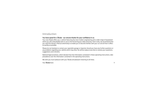 2
2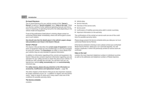 3
3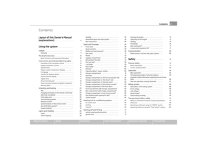 4
4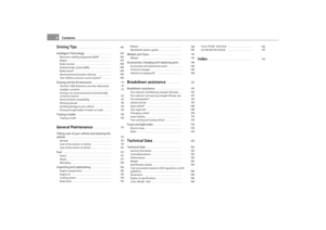 5
5 6
6 7
7 8
8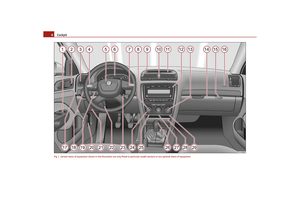 9
9 10
10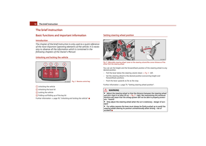 11
11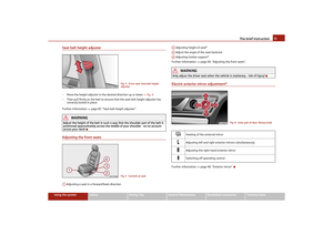 12
12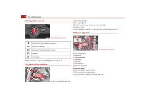 13
13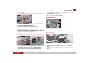 14
14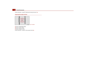 15
15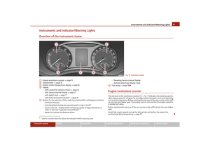 16
16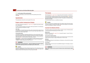 17
17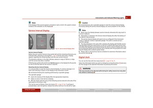 18
18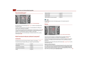 19
19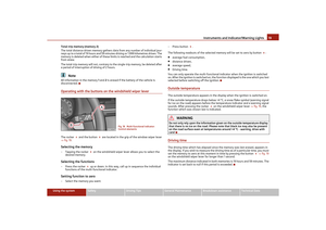 20
20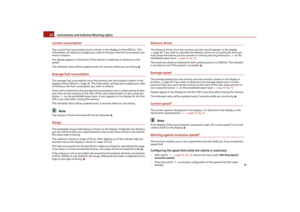 21
21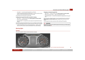 22
22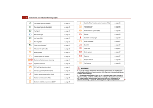 23
23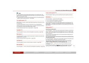 24
24 25
25 26
26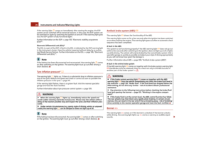 27
27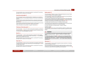 28
28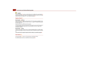 29
29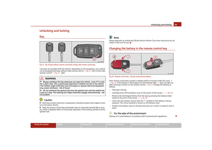 30
30 31
31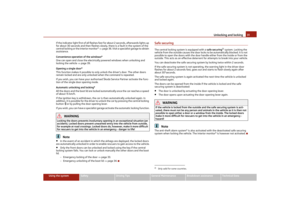 32
32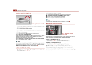 33
33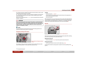 34
34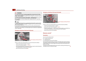 35
35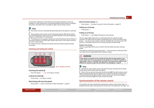 36
36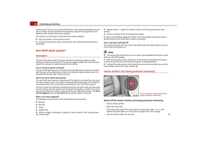 37
37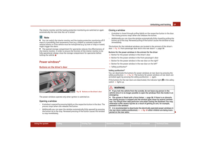 38
38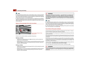 39
39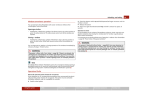 40
40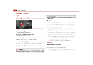 41
41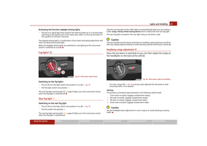 42
42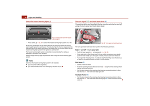 43
43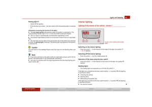 44
44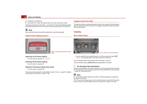 45
45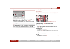 46
46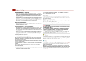 47
47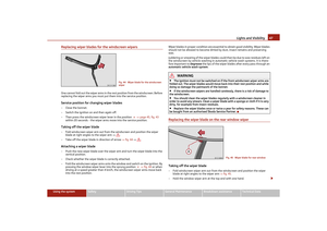 48
48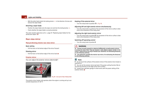 49
49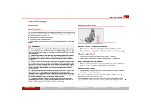 50
50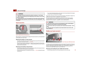 51
51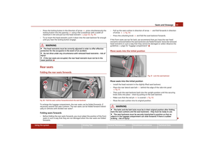 52
52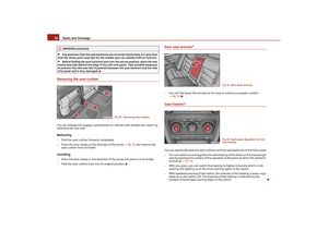 53
53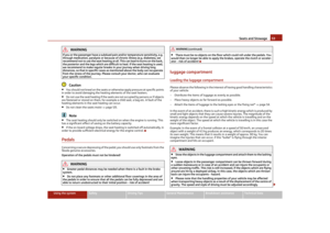 54
54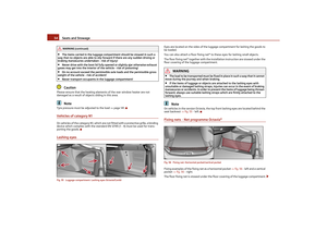 55
55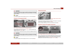 56
56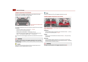 57
57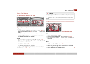 58
58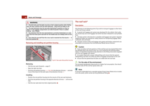 59
59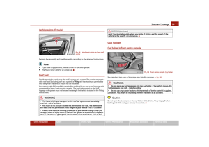 60
60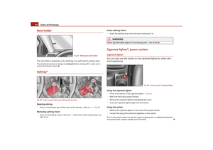 61
61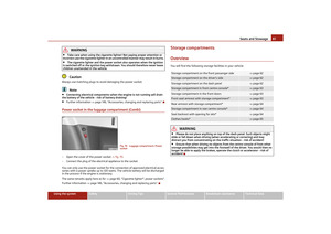 62
62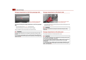 63
63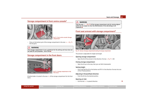 64
64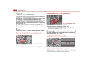 65
65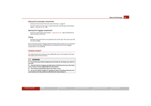 66
66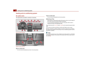 67
67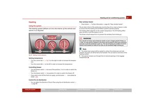 68
68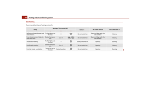 69
69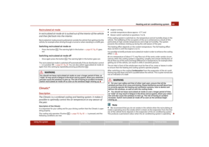 70
70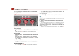 71
71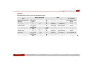 72
72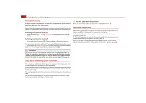 73
73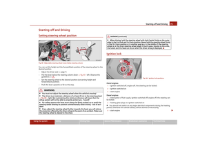 74
74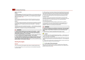 75
75 76
76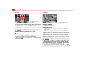 77
77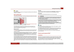 78
78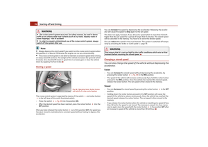 79
79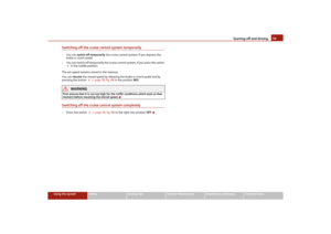 80
80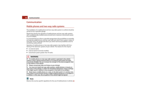 81
81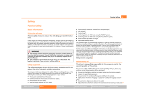 82
82 83
83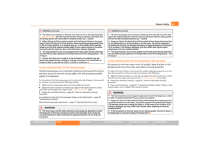 84
84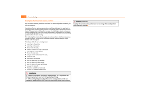 85
85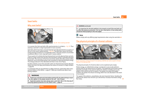 86
86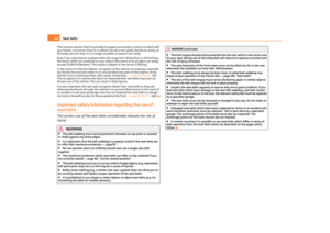 87
87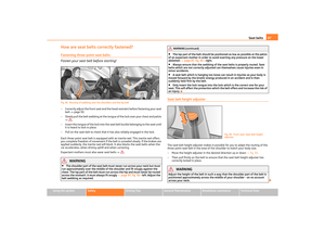 88
88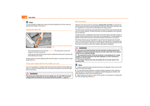 89
89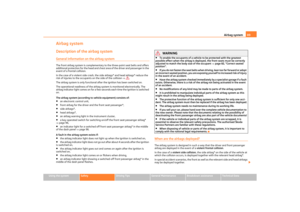 90
90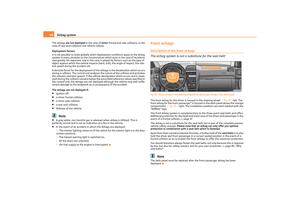 91
91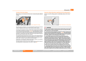 92
92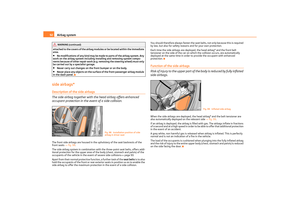 93
93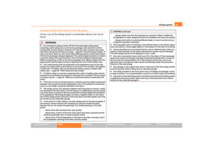 94
94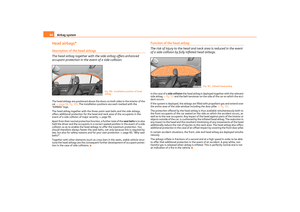 95
95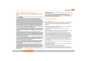 96
96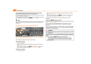 97
97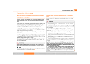 98
98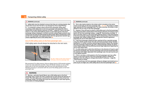 99
99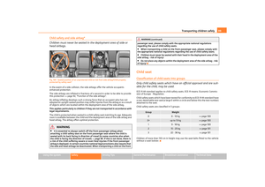 100
100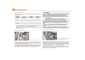 101
101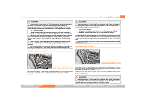 102
102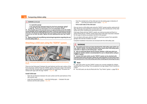 103
103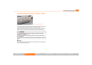 104
104 105
105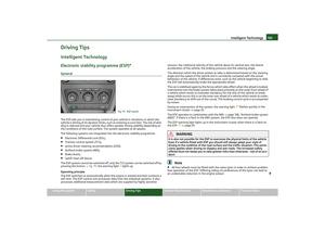 106
106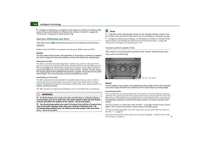 107
107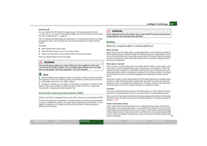 108
108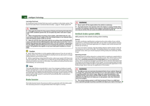 109
109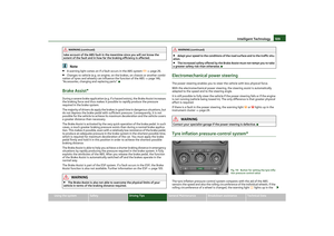 110
110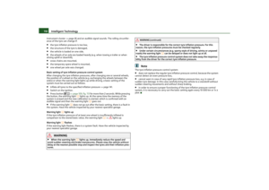 111
111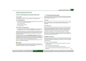 112
112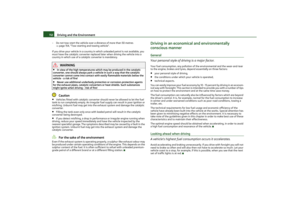 113
113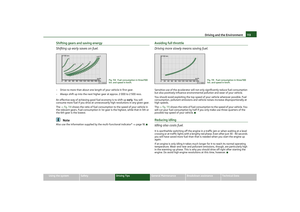 114
114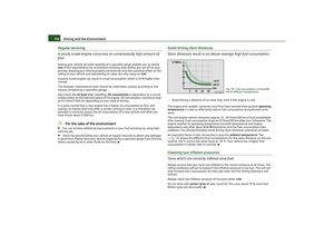 115
115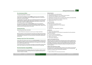 116
116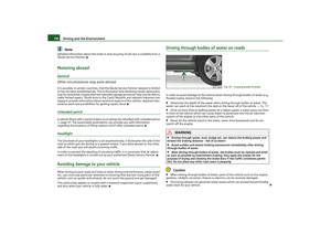 117
117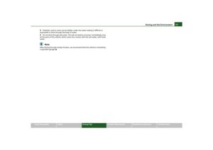 118
118 119
119 120
120 121
121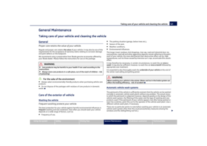 122
122 123
123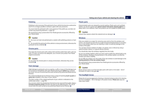 124
124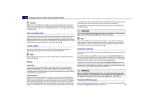 125
125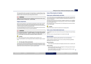 126
126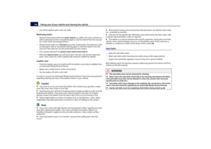 127
127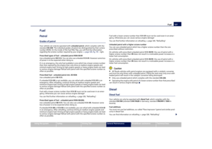 128
128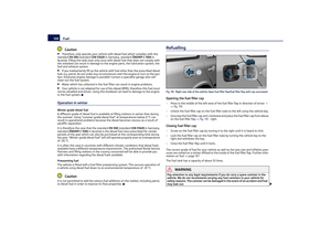 129
129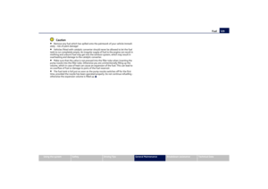 130
130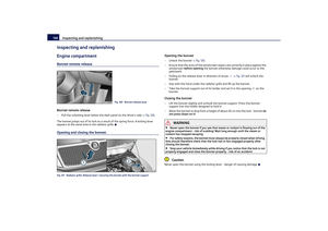 131
131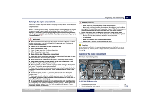 132
132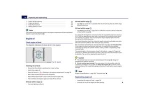 133
133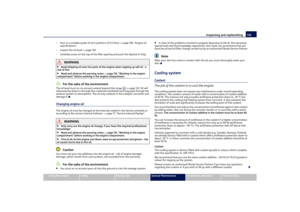 134
134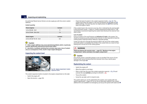 135
135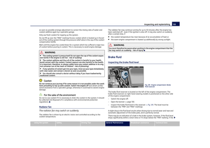 136
136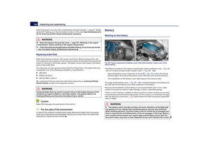 137
137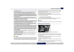 138
138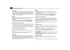 139
139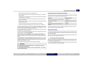 140
140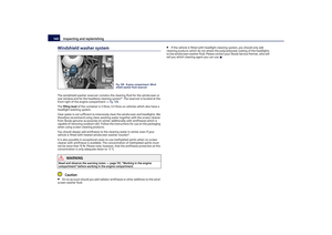 141
141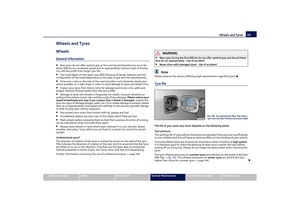 142
142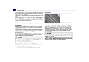 143
143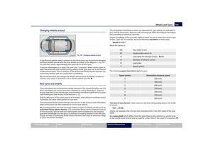 144
144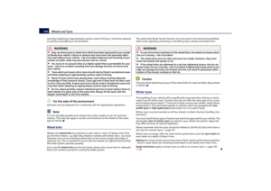 145
145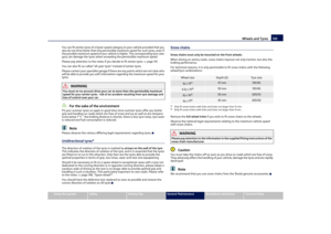 146
146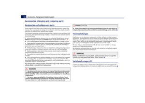 147
147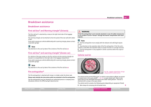 148
148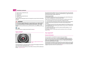 149
149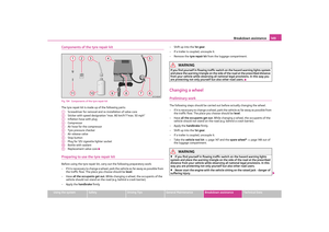 150
150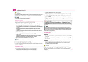 151
151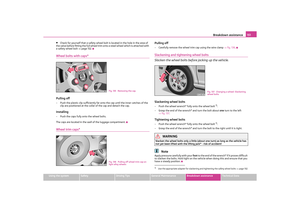 152
152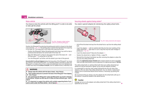 153
153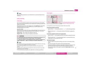 154
154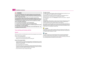 155
155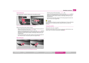 156
156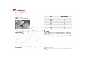 157
157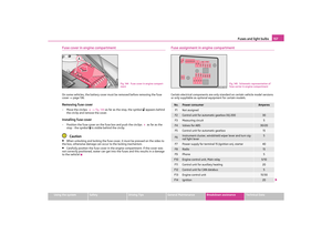 158
158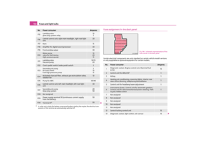 159
159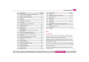 160
160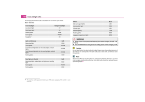 161
161 162
162 163
163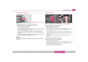 164
164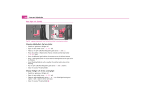 165
165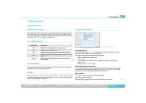 166
166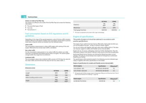 167
167 168
168 169
169 170
170 171
171 172
172 173
173 174
174 175
175 176
176 177
177 178
178 179
179 180
180 181
181 182
182