2011 SKODA OCTAVIA Owner's Manual
-
 1
1 -
 2
2 -
 3
3 -
 4
4 -
 5
5 -
 6
6 -
 7
7 -
 8
8 -
 9
9 -
 10
10 -
 11
11 -
 12
12 -
 13
13 -
 14
14 -
 15
15 -
 16
16 -
 17
17 -
 18
18 -
 19
19 -
 20
20 -
 21
21 -
 22
22 -
 23
23 -
 24
24 -
 25
25 -
 26
26 -
 27
27 -
 28
28 -
 29
29 -
 30
30 -
 31
31 -
 32
32 -
 33
33 -
 34
34 -
 35
35 -
 36
36 -
 37
37 -
 38
38 -
 39
39 -
 40
40 -
 41
41 -
 42
42 -
 43
43 -
 44
44 -
 45
45 -
 46
46 -
 47
47 -
 48
48 -
 49
49 -
 50
50 -
 51
51 -
 52
52 -
 53
53 -
 54
54 -
 55
55 -
 56
56 -
 57
57 -
 58
58 -
 59
59 -
 60
60 -
 61
61 -
 62
62 -
 63
63 -
 64
64 -
 65
65 -
 66
66 -
 67
67 -
 68
68 -
 69
69 -
 70
70 -
 71
71 -
 72
72 -
 73
73 -
 74
74 -
 75
75 -
 76
76 -
 77
77 -
 78
78 -
 79
79 -
 80
80 -
 81
81 -
 82
82 -
 83
83 -
 84
84 -
 85
85 -
 86
86 -
 87
87 -
 88
88 -
 89
89 -
 90
90 -
 91
91 -
 92
92 -
 93
93 -
 94
94 -
 95
95 -
 96
96 -
 97
97 -
 98
98 -
 99
99 -
 100
100 -
 101
101 -
 102
102 -
 103
103 -
 104
104 -
 105
105 -
 106
106 -
 107
107 -
 108
108 -
 109
109 -
 110
110 -
 111
111 -
 112
112 -
 113
113 -
 114
114 -
 115
115 -
 116
116 -
 117
117 -
 118
118 -
 119
119 -
 120
120 -
 121
121 -
 122
122 -
 123
123 -
 124
124 -
 125
125 -
 126
126 -
 127
127 -
 128
128 -
 129
129 -
 130
130 -
 131
131 -
 132
132 -
 133
133 -
 134
134 -
 135
135 -
 136
136 -
 137
137 -
 138
138 -
 139
139 -
 140
140 -
 141
141 -
 142
142 -
 143
143 -
 144
144 -
 145
145 -
 146
146 -
 147
147 -
 148
148 -
 149
149 -
 150
150 -
 151
151 -
 152
152 -
 153
153 -
 154
154 -
 155
155 -
 156
156 -
 157
157 -
 158
158 -
 159
159 -
 160
160 -
 161
161 -
 162
162 -
 163
163 -
 164
164 -
 165
165 -
 166
166 -
 167
167 -
 168
168 -
 169
169 -
 170
170 -
 171
171 -
 172
172 -
 173
173 -
 174
174 -
 175
175 -
 176
176 -
 177
177 -
 178
178 -
 179
179 -
 180
180 -
 181
181 -
 182
182 -
 183
183 -
 184
184 -
 185
185 -
 186
186 -
 187
187 -
 188
188 -
 189
189 -
 190
190 -
 191
191 -
 192
192 -
 193
193 -
 194
194 -
 195
195 -
 196
196 -
 197
197 -
 198
198 -
 199
199 -
 200
200 -
 201
201 -
 202
202 -
 203
203 -
 204
204 -
 205
205 -
 206
206 -
 207
207 -
 208
208 -
 209
209 -
 210
210 -
 211
211 -
 212
212 -
 213
213 -
 214
214 -
 215
215 -
 216
216 -
 217
217 -
 218
218 -
 219
219 -
 220
220 -
 221
221 -
 222
222 -
 223
223 -
 224
224 -
 225
225 -
 226
226 -
 227
227 -
 228
228 -
 229
229 -
 230
230 -
 231
231 -
 232
232 -
 233
233 -
 234
234 -
 235
235 -
 236
236 -
 237
237 -
 238
238 -
 239
239 -
 240
240 -
 241
241 -
 242
242 -
 243
243 -
 244
244 -
 245
245 -
 246
246 -
 247
247
 Owners Manual WARNING
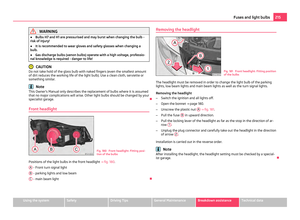
ŌŚÅ Bulbs H7 and H1 are pressurised and may burst when changing the bulb -
risk of injury!
ŌŚÅ It is recommended to wear gloves and safety glasses when changing a
bulb.
ŌŚÅ Gas discharge bulbs")
 Owners Manual Turn signal light (at the front)
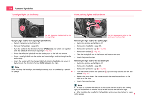
Fig. 182 Removing the light bulb for the
turn signal light
Changing light bulb for turn signal light (at the front)
ŌĆō Switch the ignition and all lights off.
ŌĆō Re")
 Owners Manual Main beam
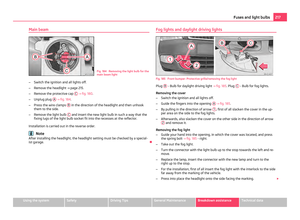
Fig. 184 Removing the light bulb for the
main beam light
ŌĆō Switch the ignition and all lights off.
ŌĆō Remove the headlight ŌćÆŌĆŖpage 215.
ŌĆō Remove the protective cap C
ŌćÆ ŌĆŖfig.")
 Owners Manual ŌĆō
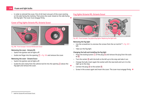
In order to reinstall the cover, first of all insert one part of the cover starting
on the side facing the marking. Then press the cover closed on the side facing
the fog light. The cover must eng")
 Owners Manual Licence plate light
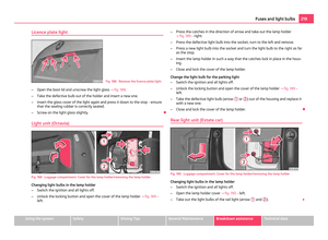
Fig. 188 Remove the licence plate light
ŌĆō Open the boot lid and unscrew the light glass ŌćÆ ŌĆŖfig. 188 .
ŌĆō Take the defective bulb out of the holder and insert a new one.
ŌĆ")
 Owners Manual ŌĆō
Press the catch in the direction of arrow and take out the lamp ŌćÆŌĆŖfig. 190 -
right.
ŌĆō Press the defective light bulb into the socket, turn to the left and remove.
ŌĆō Press a new light bulb")
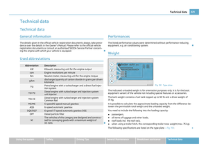
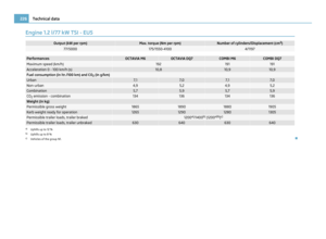
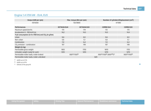
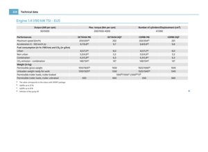
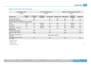
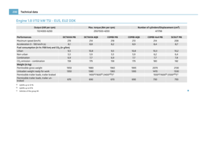
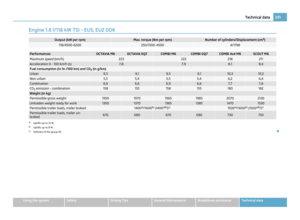
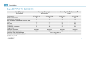
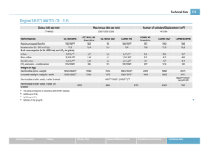
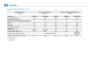
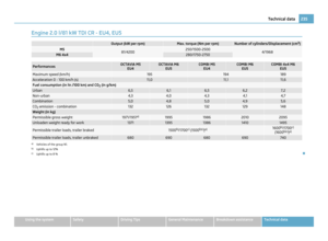
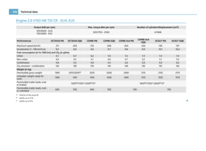
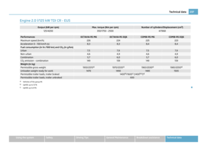
 Owners Manual Technical data
Technical data General information The details given in the official vehicle registration documents always take prece-
dence over the details in the Owners Manual. Please refer to the")
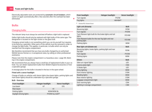
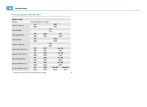
 Owners Manual Permissible gross weight
The permissible overall weight of the vehicle/trailer combination when the
vehicle is being operated with a trailer
Maximum permissible front axle load
Maximum permissible rea")