Page 209 of 248
 Owners Manual WARNING
● A discharged battery may already freeze at temperatures just below 0 °C.
In case of frozen battery carry out no jump-starting - risk of explosion!
● Please pay attention to the warning")
WARNING
● A discharged battery may already freeze at temperatures just below 0 °C.
In case of frozen battery carry out no jump-starting - risk of explosion!
● Please pay attention to the warning instructions relating to working in the
engine compartment ⇒ page 181, Working in the engine compartment
.Note
● There must not be any contact between the two vehicles otherwise current
may flow as soon as the negative terminals are connected.
● The discharged battery must be properly connected to the system of the vehi-
cle.
● Switch off any mobile phone, pay attention to the instructions for use of the
mobile phone in such a situation.
● We recommend you buy jump-start cables from a car battery specialist.
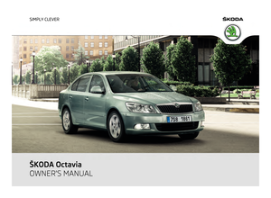
Start engine Fig. 171 Jump-starting using the battery
from another vehicle: A - flat vehicle bat-
tery, B - battery providing current
It is important to connect the jump-start cables in the correct order.
Connecting positive terminals
– Attach one end 1
⇒
fig. 171 to the positive terminal of the discharged battery
A .
– Attach the other end 2 to the positive terminal of the battery supplying the
power B . Connecting negative terminal and engine block
– Attach one end 3 to the negative terminal of the battery supplying the power
B .
– Attach the other end 4 to a solid metal part which is connected firmly to the
engine block, or to the engine block itself.
Starting engine
– Start the engine of the vehicle providing current and run the engine at idling
speed.
– Now start the engine of the vehicle with the discharged battery.
– Interrupt the attempt at starting an engine after 10 seconds if it does not start
right away and wait for about 30 seconds before repeating the attempt.
– Disconnect the cables on the engine in exactly the reverse order they were
connected up. WARNING
● The non-insulated parts of the terminal clamps must never make contact
with each other. In addition, the jump-start cable connected to the positive
terminal of the battery must not come into contact with electrically conduct-
ing parts of the vehicle - risk of short circuit!
● Do not affix the jump starting cables to the negative terminal of the dis-
charged battery. There is the risk of detonating gas seeping out the battery
being ignited by the strong spark which results from the engine being started.
● Run the jump-start cables so that they cannot be caught by any rotating
parts in the engine compartment.
● Do not bend over the batteries - risk of caustic burns!
● The vent screws of the battery cells must be tightened firmly.
● Keep any sources of ignition (naked flame, smouldering cigarettes etc.)
away from the battery - risk of an explosion!
● Never jump-start the batteries which have a too low electrolyte level - risk
of explosion and caustic burns! 207
Breakdown assistance Using the system Safety Driving Tips General Maintenance Breakdown assistance Technical data
Page 210 of 248
 Owners Manual Jump-starting in vehicles with the “START-STOP” system
Fig. 172 Jump-starting on vehicles with
the START-STOP system
On vehicles with the “START STOP” system, the negative cable of the charge")
Jump-starting in vehicles with the “START-STOP” system
Fig. 172 Jump-starting on vehicles with
the START-STOP system
On vehicles with the “START STOP” system, the negative cable of the charger
must never be connected directly to the negative pole of the vehicle battery, but
only to the engine earth ⇒ fig. 172.
Towing the vehicle General Vehicles with manual transmission can be towed in with a tow bar or a tow rope
or with the front or rear wheels raised.
Vehicles with automatic transmission can be towed in with a tow bar or a tow
rope or with the front wheels raised. If the vehicle is raised at rear, the automatic
gearbox is damaged!
Vehicles with four-wheel drive can be towed in with a tow bar or a tow rope or
with the front wheels raised.
A tow bar
is safest way of towing a vehicle and also minimizes any shocks. You
can use a tow rope only if a suitable tow bar is not available.
Refer to the following guidelines when towing:
Driver of the towing vehicle
– Release the clutch particularly gently when starting off or depress the acceler-
ator particularly gently if your vehicle is fitted with an automatic gearbox.
– On vehicles with manual transmission, only push down on the accelerator ped-
al once the rope is taught. The maximum towing speed is
50 km/h.
Driver of the towed vehicle
– Switch the ignition on so that the steering wheel is not blocked and you can
also operate the turn signal lights, the headlight flasher, the windscreen wip-
ers and windscreen washer system.
– Take the vehicle out of gear or move the selector lever into position N if your
vehicle is fitted with an automatic gearbox.
Note that the brake servo unit and power steering only operate if the engine is
running. You will require significantly greater physical force to depress the brake
pedal and to steer the vehicle if the engine is not running.
When using a tow rope, always ensure that the tow rope is always kept taught. CAUTION
● Do not tow start the engine - danger of damaging the engine. On vehicles with
a catalytic converter, unburnt fuel may get into the catalytic converter where it
may ignite. This in turn may damage or destroy the catalytic converter. You can
use the battery of another vehicle as a jump-start aid ⇒ page 206, Jump-starting
.
● If the gearbox of your vehicle no longer contains any oil because of a defect,
your vehicle must only be towed in with the driven wheels raised clear of the
ground, or on a special vehicle transporter or trailer.
● The vehicle must be transported on a special vehicle or trailer if it is not possi-
ble to tow in the vehicle in the way described or if the towing distance is greater
than 50
km.
● To protect both vehicles when tow-starting or towing, the tow rope should be
elastic. Thus one should only use plastic fibre rope or a rope made out of a similar-
ly elastic material.
● One should be constantly vigilant not to allow impermissibly high towing
forces or jerky loadings. There is always a risk of excessive stresses and damage
resulting at the points to which you attach the tow rope or tow bar when you at-
tempt to tow a vehicle which is not standing on a paved road.
● Attach the tow rope or the tow bar only to the towing eyes provided for this
purpose ⇒ page 209
, Front towing eye and ⇒ page 210, Rear towing eye. £208
Breakdown assistance
Page 211 of 248
 Owners Manual Note
● We recommend a tow rope from the range of ŠKODA Original Accessories that
you can purchase from an authorised ŠKODA Service Partner.
● Towing another vehicle requires a certain amount of")
Note
● We recommend a tow rope from the range of ŠKODA Original Accessories that
you can purchase from an authorised ŠKODA Service Partner.
● Towing another vehicle requires a certain amount of practice. Both drivers
should be familiar with the particular points about towing a vehicle. Unskilled driv-
ers should not attempt to tow in another vehicle or to be towed in.
● When towing, respect the national legal provisions, especially those which re-
late to the identification of the towing vehicle and the vehicle being towed.
● The tow rope must not be twisted as it may in certain circumstances result in
the front towing eye being unscrewed out of your vehicle.
Front towing eye The towing eye is stored in the box of the vehicle tool kit.
Fig. 173 Front bumper: protective grille/installing the towing eye
Carefully remove the cover as follows.
–
Guide the fingers into the opening A
⇒
fig. 173.
– By pulling in the direction of arrow 1 , first of all slacken the cover in the up-
per area on the side to the fog lights.
– Afterwards, also slacken the cover on the other side in the direction of arrow
2 and remove it.
– Screw in the towing eye by hand to the left up to the stop ⇒ fig. 173 - right and
tighten. For tightening, we recommend that you use for example the wheel
wrench, the lashing eye of another vehicle or a similar object which you can
push through the eye. –
In order to reinstall the cover after screwing out the towing eye, first of all in-
sert it starting on the side facing the marking. Then press the cover closed on
the side facing the fog light. The cover must engage firmly. CAUTION
The towing eye must always be screwed in fully and firmly tightened, otherwise
the towing eye can tear when towing in or tow-starting!
Front towing eye for Octavia RS and Octavia Scout The towing eye is stored in the box of the vehicle tool kit.
Fig. 174 Front bumper Octavia RS: Protective grille/Octavia Scout: Cover
Octavia RS
–
Guide one finger into the opening A of the grille
⇒ fig. 174 .
– Unlock the cover by pulling it in direction 1 and remove it.
– Screw in the towing eye by hand to the left up to the stop ⇒ fig. 173 - right and
tighten it as much as possible.
– Put the cover in place after screwing out the towing eye again and press into
place. The cover must engage firmly.
Octavia Scout
– Press on the upper part of the cover B and remove it.
– Screw in the towing eye by hand to the left up to the stop ⇒ fig. 173 - right and
tighten it as much as possible. For tightening, we recommend that you use for
example the wheel wrench, the lashing eye of another vehicle or a similar ob-
ject which you can push through the eye. £ 209
Breakdown assistance Using the system Safety Driving Tips General Maintenance Breakdown assistance Technical data
Page 212 of 248
 Owners Manual –
Put the cover in place after screwing out the towing eye again and press into
place. The cover must engage firmly. CAUTION
The towing eye must always be screwed in fully and firmly tightened, othe")
–
Put the cover in place after screwing out the towing eye again and press into
place. The cover must engage firmly. CAUTION
The towing eye must always be screwed in fully and firmly tightened, otherwise
the towing eye can tear when towing in or tow-starting.
Rear towing eye Fig. 175 Rear bumper: Remove cover/rear bumper: Installing the towing eye
–
Unlock the bottom part of the cover by pulling it downwards in direction of ar-
row 1
⇒ fig. 175.
– Unlock the upper part of the cover by pulling it in direction of arrow 2 and re-
move it.
– Screw in the towing eye by hand to the left up to the stop ⇒ fig. 175 - right and
tighten it as much as possible. For tightening, we recommend that you use for
example the wheel wrench, the lashing eye of another vehicle or a similar ob-
ject which you can push through the eye.
– In order to reinstall the cover after screwing out the towing eye, first of all in-
sert the upper part of the cover and then press in the lower part. The cover
must engage firmly. CAUTION
The towing eye must always be screwed in fully and firmly tightened, otherwise
the towing eye can tear when towing in or tow-starting. 210
Breakdown assistance
Page 213 of 248
 Owners Manual Fuses and light bulbs
Electric fuses Replacing fuses in the dash panel Defect fuses must be replaced.
Fig. 176 Fuse cover: left side of the dash
panel
Individual electrical circuits are protected by")
Fuses and light bulbs
Electric fuses Replacing fuses in the dash panel Defect fuses must be replaced.
Fig. 176 Fuse cover: left side of the dash
panel
Individual electrical circuits are protected by fuses. The fuses are located on the
left side of the dash panel behind the safety cover and under the cover in the en-
gine compartment on the left.
– Switch the ignition off and also the electrical component affected.
– Use a screwdriver to take off the fuse cover on the side of the dash panel
⇒ fig. 176 or the fuse cover in the engine compartment ⇒ page 211.
– Find out which fuse belongs to the relevant component ⇒ page 213, Fuse as-
signment in the dash panel or ⇒ page 212, Fuse assignment in engine compart-
ment.
– Take the plastic clip out of its fixture in the fuse cover, insert it onto the re-
spective fuse and pull out this fuse.
– Defect fuses can be detected by their melted metal strips. Replace the defect
fuse by a new fuse of the same ampere number.
– Fit on the fuse cover again.
We recommend that you always have the small box of replacement fuses in your
vehicle. You can obtain replacement fuses from the range of
ŠKODA Original Parts
or from a specialist garage. Colour coding of fuses Colour Maximum amperage
light brown 5
brown 7,5
red 10
blue 15
yellow 20
white 25
green 30
orange 40
red 50
CAUTION
● Never attempt to
“repair” fuses and also do not replace them with a fuse of a
higher amperage - risk of fire! This may also cause damage at another part of the
electrical system.
● Have the electrical system checked as quickly as possible by a specialist ga-
rage if a newly inserted fuse blows again after a short time.
Fuse cover in engine compartment Fig. 177 Fuse cover in engine compart-
ment
On some vehicles, the battery cover must be removed before removing the fuse
cover ⇒ page 188
. £ 211
Fuses and light bulbs Using the system Safety Driving Tips General Maintenance Breakdown assistance Technical data
Page 214 of 248
 Owners Manual Removing fuse cover
–
Move the circlips A ⇒
fig. 177 as far as the stop, the symbol appears behind
the circlip and remove the cover.
Installing fuse cover
– Position the fuse cover on t")
Removing fuse cover
–
Move the circlips A ⇒
fig. 177 as far as the stop, the symbol appears behind
the circlip and remove the cover.
Installing fuse cover
– Position the fuse cover on the fuse box and push the circlips A as far as the
stop - the symbol is visible behind the circlip. CAUTION
● When unlocking and locking the fuse cover, it must be pressed on the sides to
the box, otherwise damage can occur to the locking mechanism.
● Carefully position the fuse cover in the engine compartment. If the cover was
not correctly positioned, water can get into the fuses and this results in a damage
to the vehicle!
Fuse assignment in engine compartment Fig. 178 Schematic representation of
fuse carrier in engine compartment
Certain electrical components are only standard on certain vehicle model versions
or only available as optional equipment for certain models. No. Power consumer
F1 Not assigned
F2 Control unit for automatic gearbox DQ 200
F3 Measuring circuit
F4 Valves for ABS
F5 Control unit for automatic gearbox
F6 Instrument cluster, windshield wiper lever and turn signal light lever
F7 Power supply terminal 15, Starter No. Power consumer
F8 Radio
F9 Not assigned
F10 Engine control unit, Main relay
F11 Control unit for auxiliary heating
F12 Control unit for CAN databus
F13 Engine control unit
F14 Ignition
F15 Lambda probe
glow plug system relay
F16 Central control unit, right main headlight, right rear light unit
F17 Horn
F18 Amplifier for digital sound processor
F19 Front window wiper
F20 Water pump
valve for fuel dosing
F21 Lambda probe
F22 Clutch pedal switch, brake pedal switch
F23 Secondary air pump
Air mass meter
Fuel high pressure pump
F24 Activated charcoal filter, exhaust gas recirculation valve
F25 Pump for ABS
F26 Central control unit, left main headlight, left rear light unit
F27 Secondary air pump
Glow plug system
F28 Not assigned
F29 Power supply terminal 30
F30 Terminal X
a) a)
In order not to drain the battery unnecessarily when starting the engine, the electrical components
of this terminal are automatically switched off. 212
Fuses and light bulbs
Page 215 of 248
 Owners Manual Fuse assignment in the dash panel
Fig. 179 Schematic representation of
the fuse carrier in the dash panel
Certain electrical components are only standard on certain vehicle model versions
or only ava")
Fuse assignment in the dash panel
Fig. 179 Schematic representation of
the fuse carrier in the dash panel
Certain electrical components are only standard on certain vehicle model versions
or only available as optional equipment for certain models. No. Power consumer
1 Diagnostic socket, Engine control unit, Electrical fuel pump
2 Control unit for ABS, ESP
3 Airbag
4 Heating, Air conditioning system, Reversing lights
5 Control unit for headlamp beam adjustment
6 Instrument cluster, control unit for automatic gearbox, control unit for
electromechanical power steering, parking aid, Haldex coupling 7 Not assigned
8 Not assigned
9 Not assigned
10 Not assigned
11 Not assigned
12 Central locking control unit
13 Diagnostic socket, Light switch
14 Control unit for automatic gearbox, Selector lever lock
15 Central control unit - interior lights
16 Climatronic
17 Not assigned
18 Rear window wiper
19 Control unit for trailer detection No. Power consumer
20 Not assigned
21 Cornering lights for the left and right side
22 Air blower for Climatronic
23 Front power window
24 Cigarette lighter
25 Rear window heater
Rear window heater, Auxiliary heating (auxiliary heating and ventila-
tion)
26 Power socket in the luggage compartment
27 Fuel pump relay, Injection valves (diesel engine)
28 Radio
29 Engine control unit, Crankcase ventilation heater
30 Control unit for automatic gearbox
31 Vacuum pump
32 Rear power window
33 Electric sliding/tilting roof
34 Control unit for convenience functions
35 Anti-theft alarm system
36 Headlight cleaning system
37 Front seat heating
38 Heated rear seats
39 Instrument cluster, windshield wiper lever and turn signal light lever
40 Air blower for heating and air conditioning
41 Not assigned
42 Not assigned
43 Towing device
44 Towing device
45 Towing device
46 Seat heaters
47 Relay for auxiliary heating
48 Phone
49 Light switch
£ 213
Fuses and light bulbs Using the system Safety Driving Tips General Maintenance Breakdown assistance Technical data
Page 216 of 248
 Owners Manual Electrically adjustable seats are protected by
automatic circuit breakers, which
switch on again automatically after a few seconds after the overload has been
eliminated.
Bulbs Changing bulbs The")
Electrically adjustable seats are protected by
automatic circuit breakers, which
switch on again automatically after a few seconds after the overload has been
eliminated.
Bulbs Changing bulbs The relevant lamp must always be switched off before a light bulb is replaced.
Defect light bulbs should only be replaced with light bulbs of the same type. The
designation is located on the light socket or the glass bulb.
Changing certain bulbs is not something which you can do yourself, but requires
to be done by a specialist. Other parts of the vehicle must be removed in order to
change the light bulbs. This applies, in particular, to bulbs which can only be
reached from the engine compartment.
We therefore recommend that you have any bulbs changed by an authorised
ŠKODA
Service Partner or, in exceptional cases, by calling on other professional
assistance.
Please note that the engine compartment is a hazardous area ⇒ page 181, Work-
ing in the engine compartment.
We recommend that you always have a small box of replacement bulbs in your ve-
hicle. You can obtain replacement bulbs from ŠKODA Original Accessories or from
a specialist garage.
A stowage place for the bulbs is located in the box in the spare wheel.
Fitted with a xenon headlight
Change of bulbs on vehicles with Xenon lights (low beam lights, parking lights and
main beam lights) should be undertaken by a specialist garage.
Bulb - Overview Front headlight Halogen headlight Xenon headlight
Low beam H7 D1S
Main beam H1
Parking lights W5W/W5W BL
Daylight driving lights PY21W SLL/LED
a) Front headlight Halogen headlight Xenon headlight
Turn signals PY21W
Fog lights H8/HB4
a) a)
Octavia RS, Octavia Scout Light unit (Octavia) Bulb
Reversing light P21W
Turn signals PY21W
Twin filament light bulb for the brake lights and tail
lights
P21/4W
Twin filament bulbs for the rear fog light and rear
parking light. P21/4W
Parking lights W3W
Rear light unit (Estate car) Bulb
Reversing lights, brake lights, parking light and rear
fog light
P21W
Turn signals PY21W
Parking lights W3W
Others Bulb
Side turn signal lights LED
Licence plate light C5W
3. Brake light LED
Entry lighting W5W
front interior lighting C10W
Reading lights W5W
Rear interior lighting C10W
Luggage compartment light W5W
Door warning light C5W
Lighting in storage compartment C3W
£214
Fuses and light bulbs
 1
1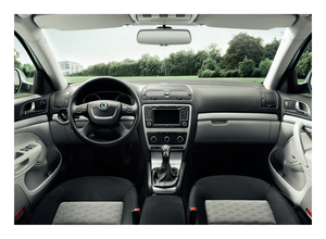 2
2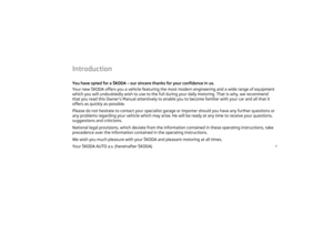 3
3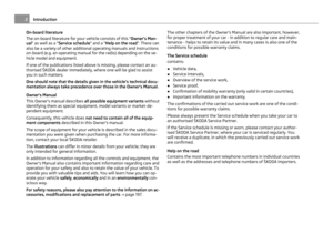 4
4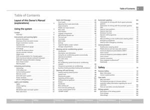 5
5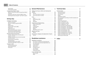 6
6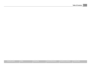 7
7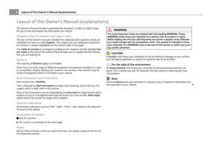 8
8 9
9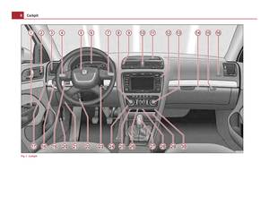 10
10 11
11 12
12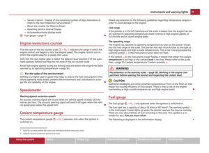 13
13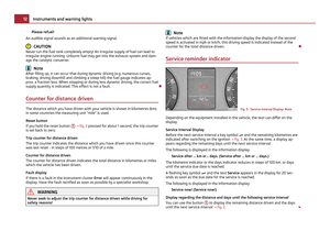 14
14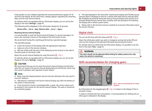 15
15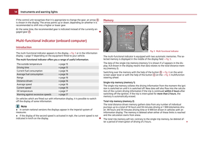 16
16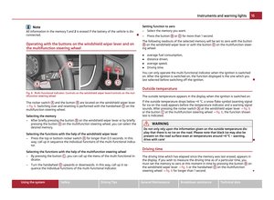 17
17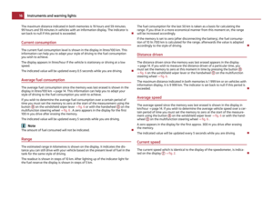 18
18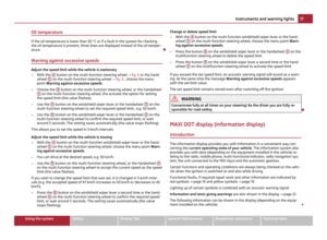 19
19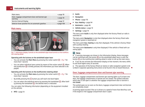 20
20 21
21 22
22 23
23 24
24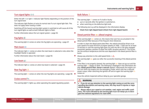 25
25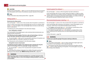 26
26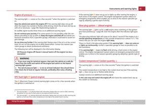 27
27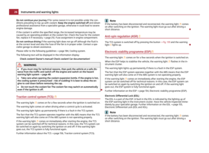 28
28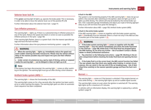 29
29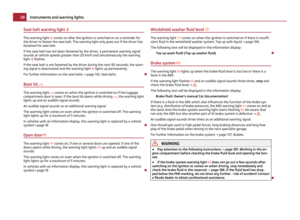 30
30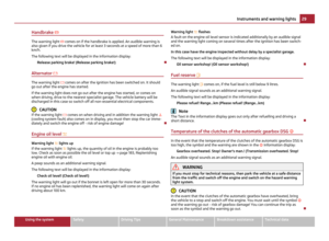 31
31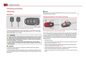 32
32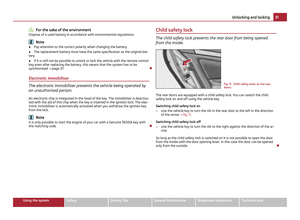 33
33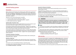 34
34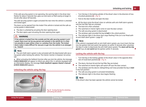 35
35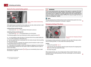 36
36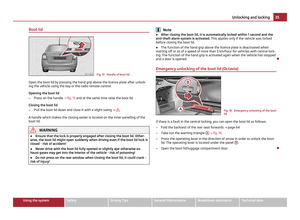 37
37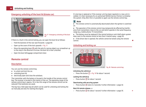 38
38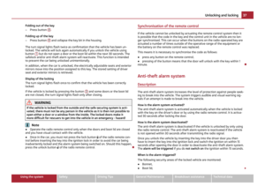 39
39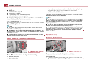 40
40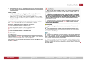 41
41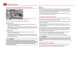 42
42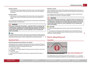 43
43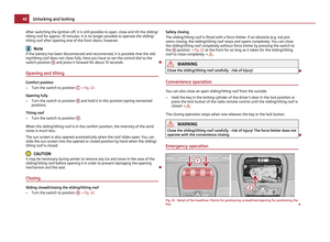 44
44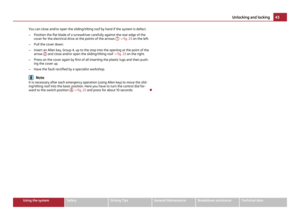 45
45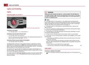 46
46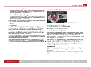 47
47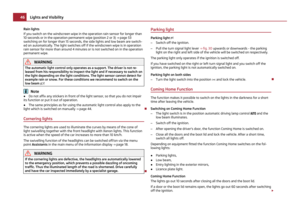 48
48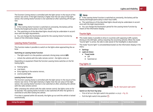 49
49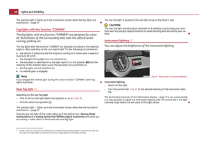 50
50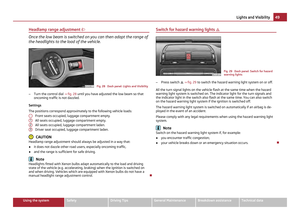 51
51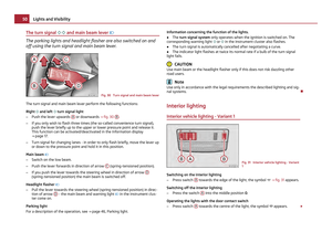 52
52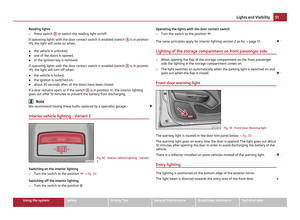 53
53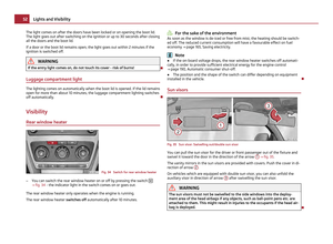 54
54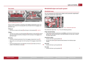 55
55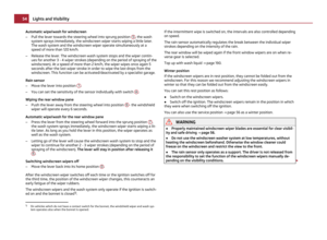 56
56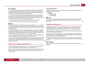 57
57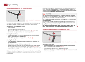 58
58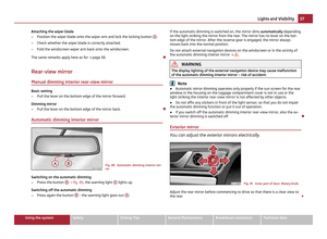 59
59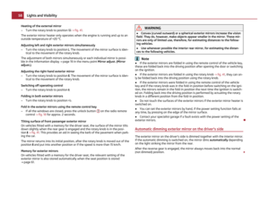 60
60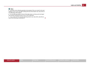 61
61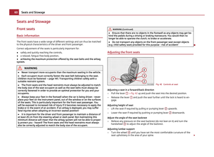 62
62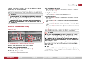 63
63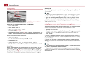 64
64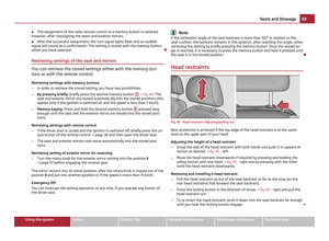 65
65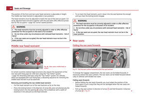 66
66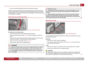 67
67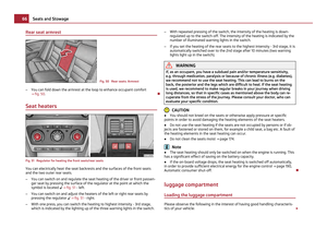 68
68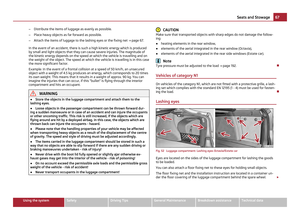 69
69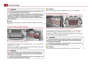 70
70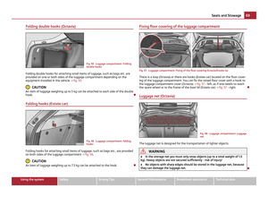 71
71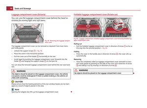 72
72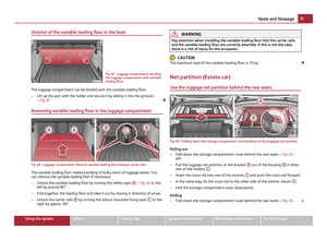 73
73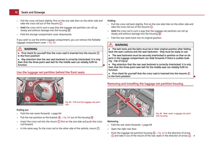 74
74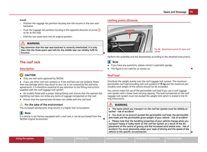 75
75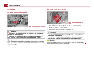 76
76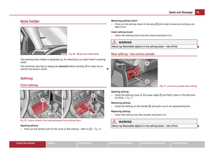 77
77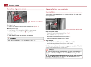 78
78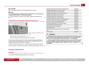 79
79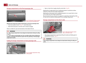 80
80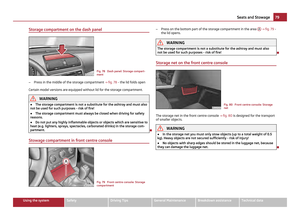 81
81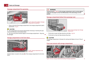 82
82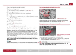 83
83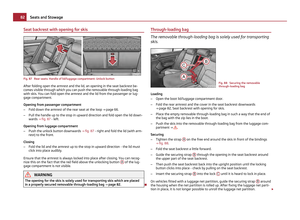 84
84 85
85 86
86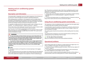 87
87 88
88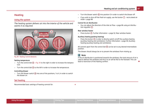 89
89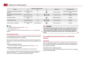 90
90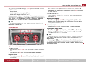 91
91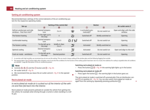 92
92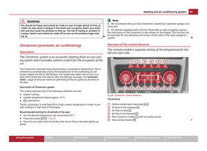 93
93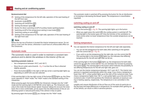 94
94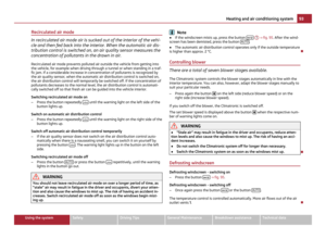 95
95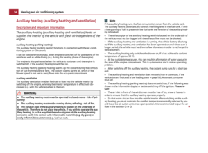 96
96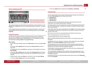 97
97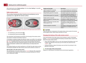 98
98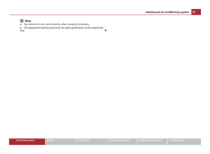 99
99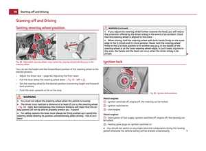 100
100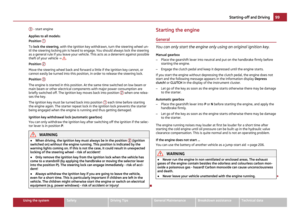 101
101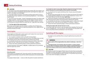 102
102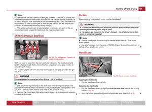 103
103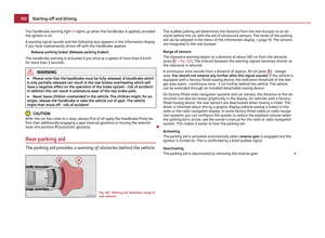 104
104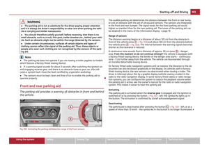 105
105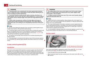 106
106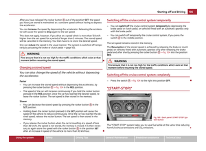 107
107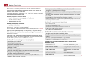 108
108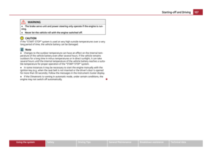 109
109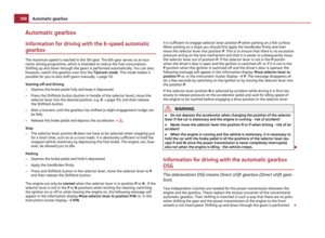 110
110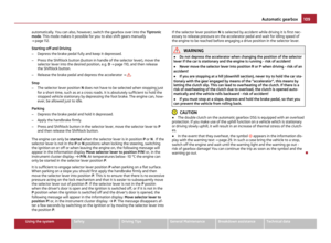 111
111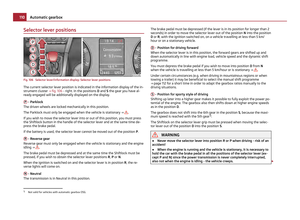 112
112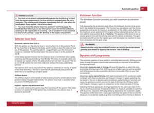 113
113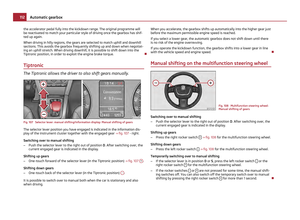 114
114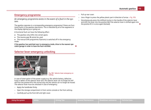 115
115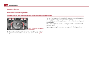 116
116 117
117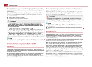 118
118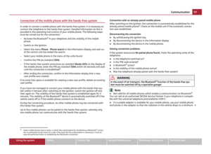 119
119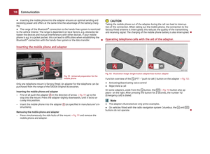 120
120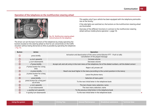 121
121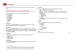 122
122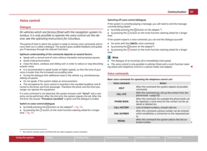 123
123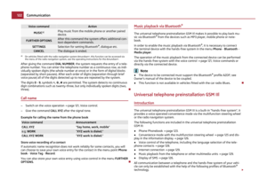 124
124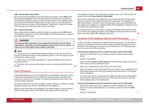 125
125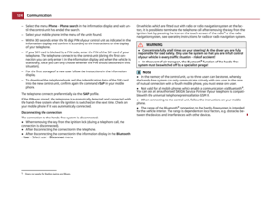 126
126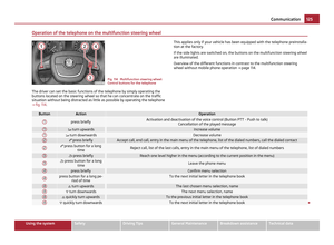 127
127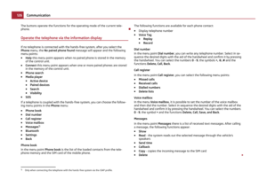 128
128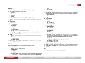 129
129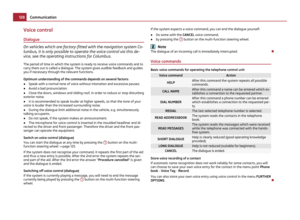 130
130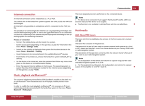 131
131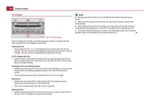 132
132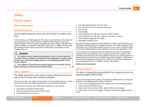 133
133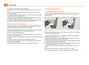 134
134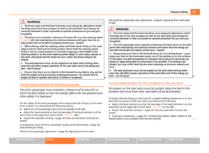 135
135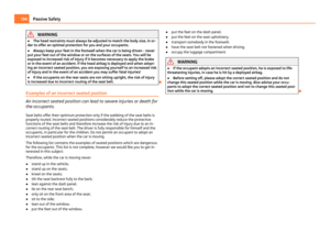 136
136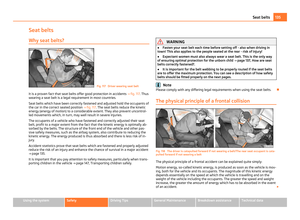 137
137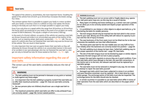 138
138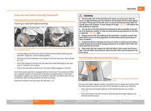 139
139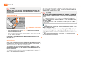 140
140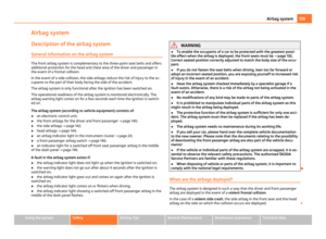 141
141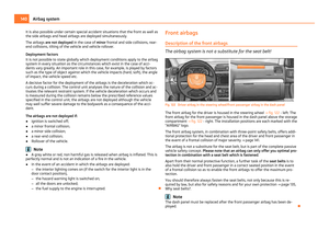 142
142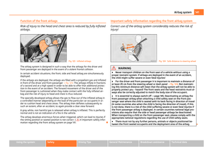 143
143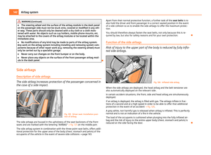 144
144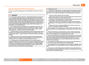 145
145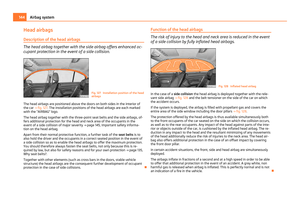 146
146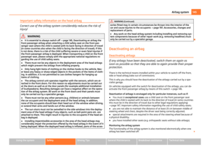 147
147 148
148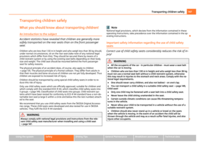 149
149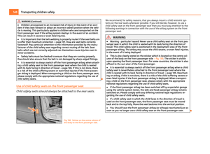 150
150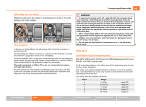 151
151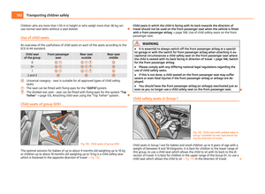 152
152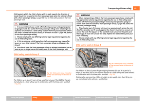 153
153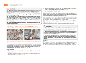 154
154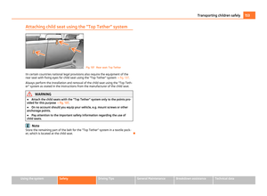 155
155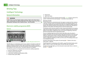 156
156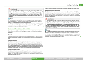 157
157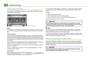 158
158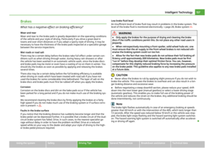 159
159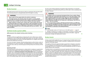 160
160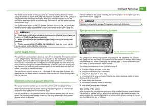 161
161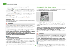 162
162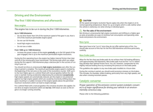 163
163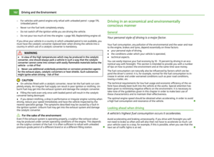 164
164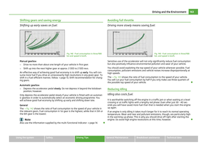 165
165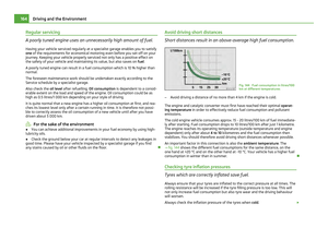 166
166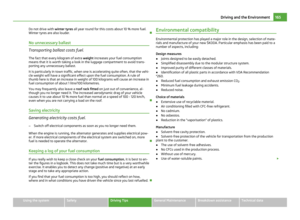 167
167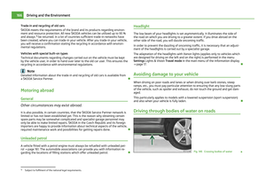 168
168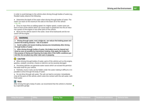 169
169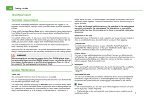 170
170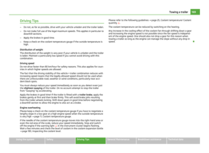 171
171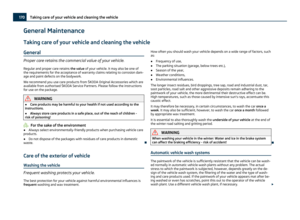 172
172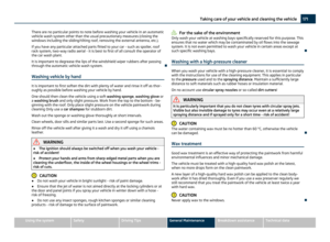 173
173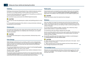 174
174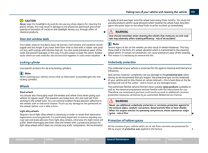 175
175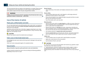 176
176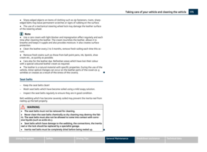 177
177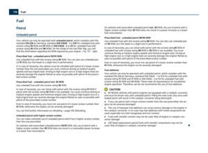 178
178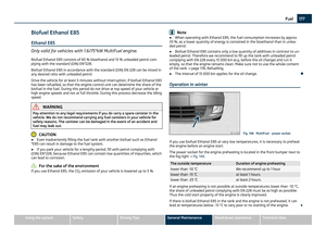 179
179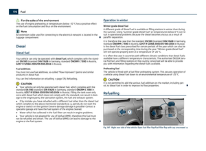 180
180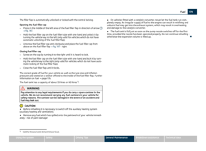 181
181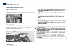 182
182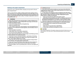 183
183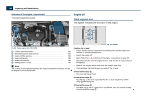 184
184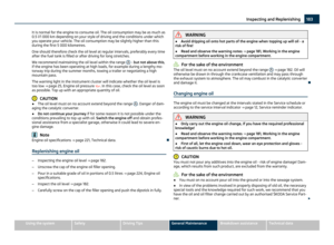 185
185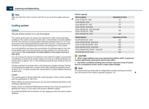 186
186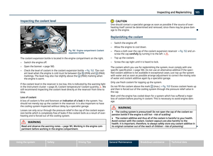 187
187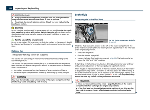 188
188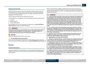 189
189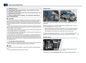 190
190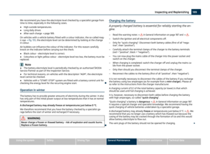 191
191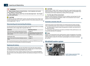 192
192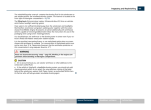 193
193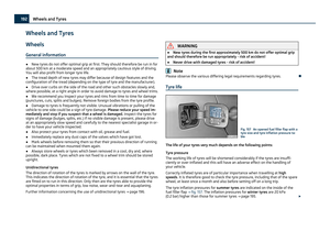 194
194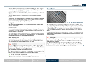 195
195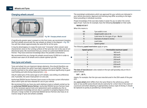 196
196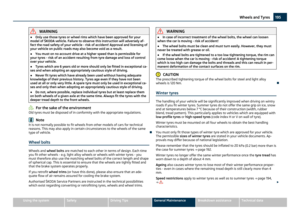 197
197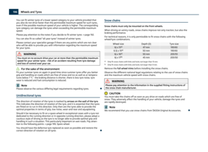 198
198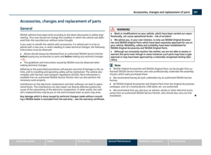 199
199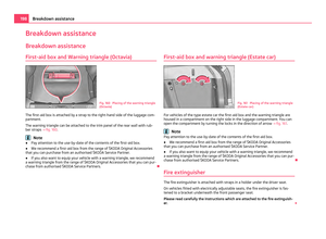 200
200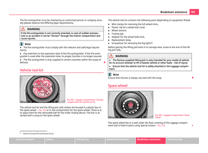 201
201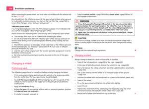 202
202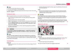 203
203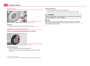 204
204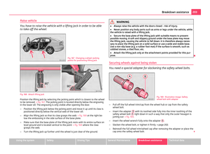 205
205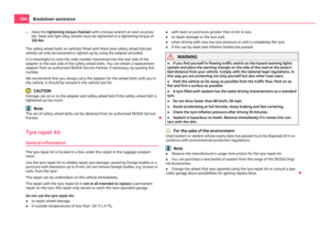 206
206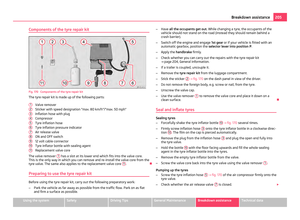 207
207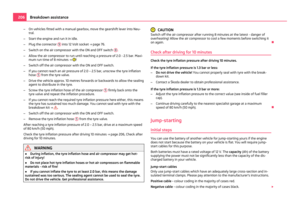 208
208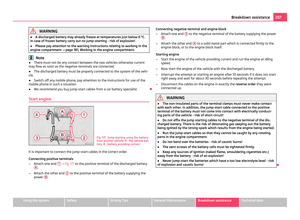 209
209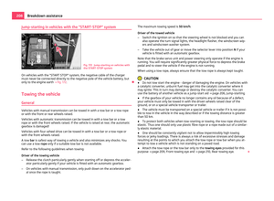 210
210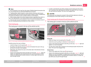 211
211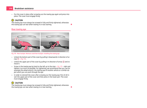 212
212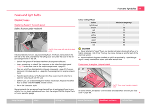 213
213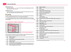 214
214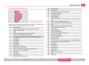 215
215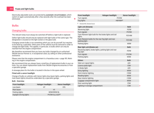 216
216 217
217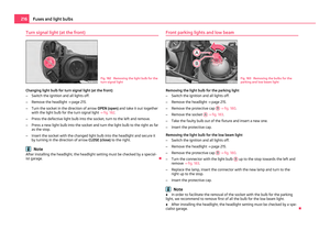 218
218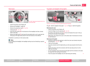 219
219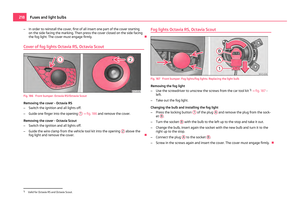 220
220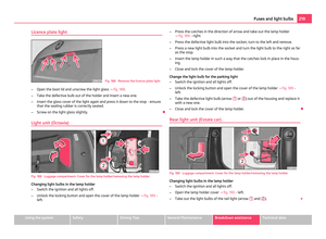 221
221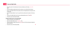 222
222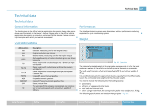 223
223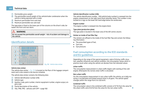 224
224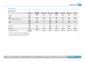 225
225 226
226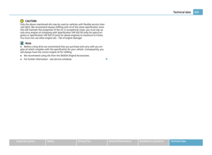 227
227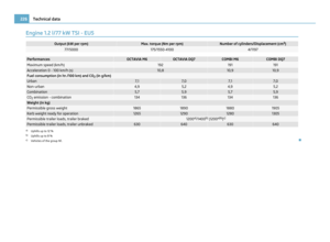 228
228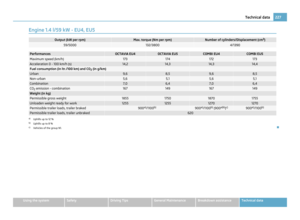 229
229 230
230 231
231 232
232 233
233 234
234 235
235 236
236 237
237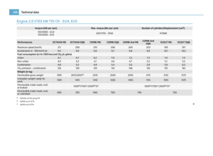 238
238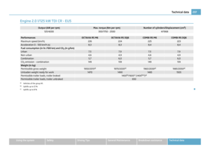 239
239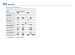 240
240 241
241 242
242 243
243 244
244 245
245 246
246 247
247