2011 INFINITI QX56 sensor
[x] Cancel search: sensorPage 1757 of 5598
RADIATOR CORE SUPPORTDLK-221
< REMOVAL AND INSTALLATION >
C
DE
F
G H
I
J
L
M A
B
DLK
N
O P
6. Disconnect all harness clips.
7. Remove hood lock assembly. Refer to DLK-238, "
Removal and Installation".
8. Remove fixing clips of air guide seal.
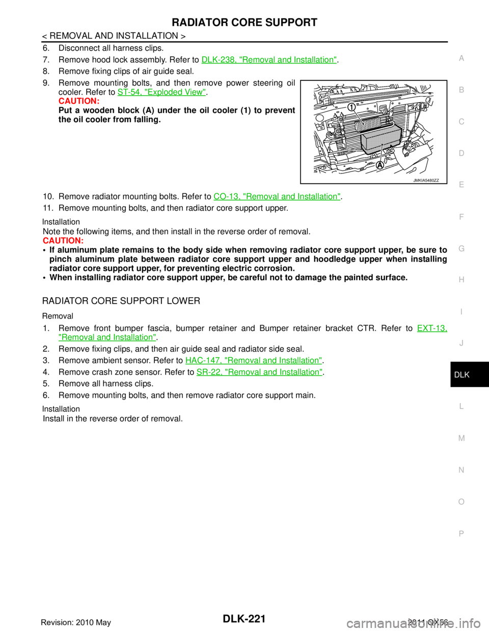
9. Remove mounting bolts, and then remove power steering oil cooler. Refer to ST-54, "
Exploded View".
CAUTION:
Put a wooden block (A) under the oil cooler (1) to prevent
the oil cooler from falling.
10. Remove radiator mounting bolts. Refer to CO-13, "
Removal and Installation".
11. Remove mounting bolts, and then radiator core support upper.
Installation
Note the following items, and then install in the reverse order of removal.
CAUTION:
If aluminum plate remains to the body side when removing radiator core support upper, be sure to
pinch aluminum plate between radiator core support upper and hoodledge upper when installing
radiator core support upper, for preventing electric corrosion.
When installing radiator core support upper, be careful not to damage the painted surface.
RADIATOR CORE SUPPORT LOWER
Removal
1. Remove front bumper fascia, bumper retainer and Bumper retainer bracket CTR. Refer to EXT-13,
"Removal and Installation".
2. Remove fixing clips, and then air guide seal and radiator side seal.
3. Remove ambient sensor. Refer to HAC-147, "
Removal and Installation".
4. Remove crash zone sensor. Refer to SR-22, "
Removal and Installation".
5. Remove all harness clips.
6. Remove mounting bolts, and then remove radiator core support main.
Installation
Install in the reverse order of removal.
JMKIA5480ZZ
Revision: 2010 May2011 QX56
Page 1782 of 5598
DLK-246
< REMOVAL AND INSTALLATION >
BACK DOOR LOCK
BACK DOOR LOCK
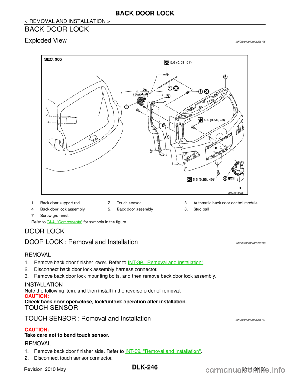
Exploded ViewINFOID:0000000006226105
DOOR LOCK
DOOR LOCK : Removal and InstallationINFOID:0000000006226106
REMOVAL
1. Remove back door finisher lower. Refer to INT-39, "Removal and Installation".
2. Disconnect back door lock assembly harness connector.
3. Remove back door lock mounting bolts, and then remove back door lock assembly.
INSTALLATION
Note the following item, and then install in the reverse order of removal.
CAUTION:
Check back door open/close, lock/unlo ck operation after installation.
TOUCH SENSOR
TOUCH SENSOR : Removal and InstallationINFOID:0000000006226107
CAUTION:
Take care not to bend touch sensor.
REMOVAL
1. Remove back door finisher side. Refer to INT-39, "Removal and Installation".
2. Disconnect touch sensor connector.
1. Back door support rod 2. Touch sensor 3. Automatic back door control module
4. Back door lock assembly 5. Back door assembly 6. Stud ball
7. Screw grommet
Refer to GI-4, "
Components" for symbols in the figure.
JMKIA5484GB
Revision: 2010 May2011 QX56
Page 1783 of 5598
BACK DOOR LOCKDLK-247
< REMOVAL AND INSTALLATION >
C
DE
F
G H
I
J
L
M A
B
DLK
N
O P
3. Remove clips and TORX screws of touch sensor.
4. Pull harness of touch sensor out of back door and remove touch sensor.
INSTALLATION
Note the following item, and then install in the reverse order of removal.
CAUTION:
Check back door open/close operation after installation.
BACK DOOR SUPPORT ROD
BACK DOOR SUPPORT ROD : Removal and InstallationINFOID:0000000006226108
REMOVAL
1. Remove cap of back door finisher side (LH). Refer to INT-39, "Exploded View".
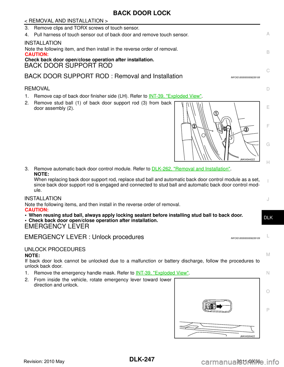
2. Remove stud ball (1) of back door support rod (3) from back door assembly (2).
3. Remove automatic back door control module. Refer to DLK-262, "
Removal and Installation".
NOTE:
When replacing back door support rod, replace stud ba ll and automatic back door control module as a set,
since back door support rod is engaged and connected to stud ball and automatic back door control mod-
ule.
INSTALLATION
Note the following items, and then install in the reverse order of removal.
CAUTION:
When reusing stud ball, always a pply locking sealant before installing stud ball to back door.
Check back door open/close opera tion after installation.
EMERGENCY LEVER
EMERGENCY LEVER : Unlock proceduresINFOID:0000000006226109
UNLOCK PROCEDURES
NOTE:
If back door lock cannot be unlocked due to a malfuncti on or battery discharge, follow the procedures to
unlock back door.
1. Remove the emergency handle mask. Refer to INT-39, "
Exploded View".
2. From inside the vehicle, rotate emergency lever toward lower direction and unlock.
JMKIA5442ZZ
JMKIA5264ZZ
Revision: 2010 May2011 QX56
Page 1788 of 5598
DLK-252
< REMOVAL AND INSTALLATION >
CAB MOUNTING INSULATOR
Drain brake fluid from brake line. Refer to BR-10, "Draining".
Release fuel pressure. Refer to EC-153, "
Work Procedure".
Disconnect both battery cables. Refer to PG-164, "
Removal and Installation".
Drain engine coolant from radiator. Refer to CO-8, "
Draining".
Discharge refrigerant from A/C circuit. Refer to HA-20, "
Recycle Refrigerant".
Drain power steering fluid from reservoir tank.
4. Remove parts relating to connection of body assembly and frame assembly. Tire and wheel: Refer to WT-64, "
Removal and Installation" (with TPMS).
Front fender protector (LH and RH): Refer to EXT-23, "
FENDER PROTECTOR : Removal and Installa-
tion".
Front bumper: Refer to EXT-13, "
Removal and Installation".
Radiator core support upper: Refer to DLK-220, "
Removal and Installation".
Fan shroud: Refer to CO-16, "
Removal and Installation".
Battery and battery case: Refer to PG-164, "
Removal and Installation".
Air cleaner case (upper and lower): Refer to EM-27, "
Removal and Installation".
Engine cover: Refer to EM-25, "
Removal and Installation".
Rear wheel house protector (LH and RH): EXT-24, "
REAR WHEEL HOUSE PROTECTOR : Removal
and Installation".
Rear bumper: Refer to EXT-17, "
Removal and Installation".
Fuel filler tube: Remove to FL-8, "
Exploded View".
Spare tire
Towing hook bracket.
5. Separate parts relating to connection of body assembly and frame assembly. Vehicle front
Disconnect ICC sensor connector. (models with ICC) Refer to CCS-176, "
Removal and Installation".
Remove radiator upper hose and radiator lower hose from radiator assembly. Refer to CO-13,
"Exploded View".
Remove A/T fluid cooler hose B and A/T fluid cooler hose E from A/T fluid cooler tubes. Refer to TM-
202, "Exploded View".
Remove power steering return hose from oil cooler, and then power steering return hose clamp bolt from frame assembly. Refer to ST-54, "
Exploded View".
Remove power steering suction hose from reservoir tank. Refer to ST-54, "
Exploded View".
CAUTION:
Never spill power steering fluid in engine room.
Remove A/C low-presser flexible hose from A/C low-presser pipe. Refer to HA-35, "
LOW-PRESSURE
FLEXIBLE HOSE : Removal and Installation".
Remove A/C hi-presser flexible hose from condenser. Refer to HA-34, "
HIGH-PRESSURE FLEXIBLE
HOSE : Removal and Installation".
Remove all engine Control Harness connectors, har ness clips and others that are connected to the
body assembly side of the engine room. (engine room LH and RH side). Refer to PG-148, "
Engine Con-
trol Harness".
NOTE:
Separate harness connectors from ECM (engine control module). Refer to EC-10, "
General Precau-
tions".
CAUTION:
When pulling out harnesses, never damage harnesses or connectors.
After temporarily securing connectors, cover th em with vinyl or similar material to protect
against adhesion of foreign materials.
Disconnect engine room harness connectors and remo ve harness clips from engine assembly (engine
RH side). Refer to PG-146, "
Engine Room Harness".
Remove heater hoses from front water outlet tube (engine room RH side). Refer to HA-33, "
Exploded
View".
Disconnect front wheel sensor connectors (LH and RH). Refer to BRC-134, "
FRONT WHEEL SENSOR
: Exploded View".
Disconnect fuel feed tube and EVAP hos e (front wheel well LH side).
Remove steering lower shaft from steering gear side assembly. Refer to ST-37, "
Removal and Installa-
tion"
CAUTION:
Spiral cable may be cut if steering wheel turns while separating steering column assembly and
steering gear assembly.
Revision: 2010 May2011 QX56
Page 1803 of 5598
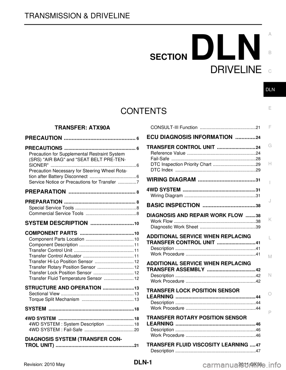
DLN-1
TRANSMISSION & DRIVELINE
CEF
G H
I
J
K L
M
SECTION DLN
A
B
DLN
N
O P
CONTENTS
DRIVELINE
TRANSFER: ATX90A
PRECAUTION ................ ...............................
6
PRECAUTIONS .............................................. .....6
Precaution for Supplemental Restraint System
(SRS) "AIR BAG" and "SEAT BELT PRE-TEN-
SIONER" ............................................................. ......
6
Precaution Necessary for Steering Wheel Rota-
tion after Battery Disconnect .....................................
6
Service Notice or Precautions for Transfer ...............7
PREPARATION ............................................8
PREPARATION .............................................. .....8
Special Service Tools .......................................... ......8
Commercial Service Tools ........................................8
SYSTEM DESCRIPTION .............................10
COMPONENT PARTS ................................... ....10
Component Parts Location .................................. ....10
Component Description ...........................................11
Transfer Control Unit ...............................................11
Transfer Control Actuator ........................................11
Transfer Hi-Lo Position Sensor ...............................12
Transfer Rotary Position Sensor .............................12
Transfer Lock Position Sensor ................................12
Transfer Fluid Temperature Sensor ........................12
STRUCTURE AND OPERATION .......................13
Sectional View ..................................................... ....13
Torque Split Mechanism .........................................13
SYSTEM .............................................................18
4WD SYSTEM ...........................................................18
4WD SYSTEM : System De scription ......................18
4WD SYSTEM : Fail-Safe ......................... ..............20
DIAGNOSIS SYSTEM (TRANSFER CON-
TROL UNIT) .................................................... ....
21
CONSULT-III Function ........................................ ....21
ECU DIAGNOSIS INFORMATION ..............24
TRANSFER CONTROL UNIT ...........................24
Reference Value .................................................. ....24
Fail-Safe ..................................................................28
DTC Inspection Priority Chart ..................................29
DTC Index ...............................................................29
WIRING DIAGRAM ......................................31
4WD SYSTEM .. ................................ .................31
Wiring Diagram .................................................... ....31
BASIC INSPECTION ...................................38
DIAGNOSIS AND REPAIR WORK FLOW .......38
Work Flow ............................................................ ....38
Diagnostic Work Sheet ............................................39
ADDITIONAL SERVICE WHEN REPLACING
TRANSFER CONTROL UNIT ...........................
41
Description ...............................................................41
Work Procedure .......................................................41
ADDITIONAL SERVICE WHEN REPLACING
TRANSFER ASSEMBLY ..................................
42
Description ...............................................................42
Work Procedure .......................................................42
TRANSFER LOCK POSITION SENSOR
LEARNING ....................................... .................
44
Description ........................................................... ....44
Work Procedure .......................................................44
TRANSFER ROTARY POSITION SENSOR
LEARNING ....................................... .................
46
Description ........................................................... ....46
Work Procedure .......................................................46
TRANSFER FLUID VISCOSITY LEARNING ....47
Description ...............................................................47
Revision: 2010 May2011 QX56
Page 1804 of 5598

DLN-2
Work Procedure ......................................................47
CONFIGURATION (TRANSFER CONTROL
UNIT) ..................................................................
48
Description ........................................................... ...48
Work Procedure ......................................................48
DTC/CIRCUIT DIAGNOSIS ...................... ...51
P1802, P1803, P1804, P1809 TRANSFER
CONTROL UNIT ............................................. ...
51
DTC Logic ............................................................ ...51
Diagnosis Procedure ..............................................51
P1807 OUT PUT SHAFT SPEED SENSOR ......52
DTC Logic ............................................................ ...52
Diagnosis Procedure ..............................................52
P1808 WHEEL SPEED SENSOR ......................53
DTC Logic ............................................................ ...53
Diagnosis Procedure ..............................................53
P180C SENSOR POWER SUPPLY (5V) ..........54
Description ........................................................... ...54
DTC Logic ...............................................................54
Diagnosis Procedure ..............................................54
P180D TRANSFER ROTARY POSITION
SENSOR ............................................................
57
DTC Logic ............................................................ ...57
Diagnosis Procedure ..............................................57
P180E SENSOR POWER SUPPLY (8V) ...........59
Description ........................................................... ...59
DTC Logic ...............................................................59
Diagnosis Procedure ..............................................59
P180F TRANSFER INTERNAL SPEED SEN-
SOR ....................................................................
61
DTC Logic ............................................................ ...61
Diagnosis Procedure ..............................................61
P1811 POWER SUPPLY CIRCUIT FOR
TRANSFER CONTROL UNIT ............................
64
Description ........................................................... ...64
DTC Logic ...............................................................64
Diagnosis Procedure ..............................................64
P1813 4WD MODE SWITCH .............................67
DTC Logic ............................................................ ...67
Diagnosis Procedure ..............................................67
Component Inspection ............................................68
P1816 PARKING/NEUTRAL POSITION
SWITCH .............................................................
69
DTC Logic ............................................................ ...69
Diagnosis Procedure ..............................................69
P1817 TRANSFER MOTOR ..............................70
DTC Logic ............................................................ ...70
Diagnosis Procedure ..............................................70
Component Inspection ......................................... ...71
P181A TRANSFER MOTOR TEMPERATURE
SENSOR ............................................................
72
DTC Logic ............................................................ ...72
Diagnosis Procedure ...............................................72
Component Inspection ............................................73
P181B INCOMPLETE SELFSHUT ....................74
DTC Logic ............................................................ ...74
Diagnosis Procedure ...............................................74
P181C TRANSFER MOTOR POWER SUP-
PLY ....................................................................
76
Description ........................................................... ...76
DTC Logic ...............................................................76
Diagnosis Procedure ...............................................76
P181E STEERING ANGLE SENSOR ...............77
DTC Logic ............................................................ ...77
Diagnosis Procedure ...............................................77
P181F INCOMPLETE CALIBRATION ..............78
DTC Logic ............................................................ ...78
Diagnosis Procedure ...............................................78
P1820 ENGINE SPEED SIGNAL ......................79
DTC Logic ............................................................ ...79
Diagnosis Procedure ...............................................79
P1826 TRANSFER FLUID TEMPERATURE ....80
DTC Logic ............................................................ ...80
Diagnosis Procedure ...............................................80
Component Inspection ............................................81
P1829 ACCELERATOR PEDAL POSITION
SENSOR ............................................................
82
DTC Logic ............................................................ ...82
Diagnosis Procedure ...............................................82
P182A TRANSFER HI-LO POSITION SEN-
SOR ...................................................................
83
DTC Logic ............................................................ ...83
Diagnosis Procedure ...............................................83
P182B TRANSFER LOCK POSITION SEN-
SOR ...................................................................
85
DTC Logic ............................................................ ...85
Diagnosis Procedure ...............................................85
P1830 ABS OPERATION SIGNAL ...................88
DTC Logic ............................................................ ...88
Diagnosis Procedure ...............................................88
P1831 VDC OPERATION SIGNAL ...................89
DTC Logic ............................................................ ...89
Diagnosis Procedure ...............................................89
P1832 TCS OPERATION SIGNAL ....................90
DTC Logic ............................................................ ...90
Diagnosis Procedure ...............................................90
Revision: 2010 May2011 QX56
Page 1805 of 5598
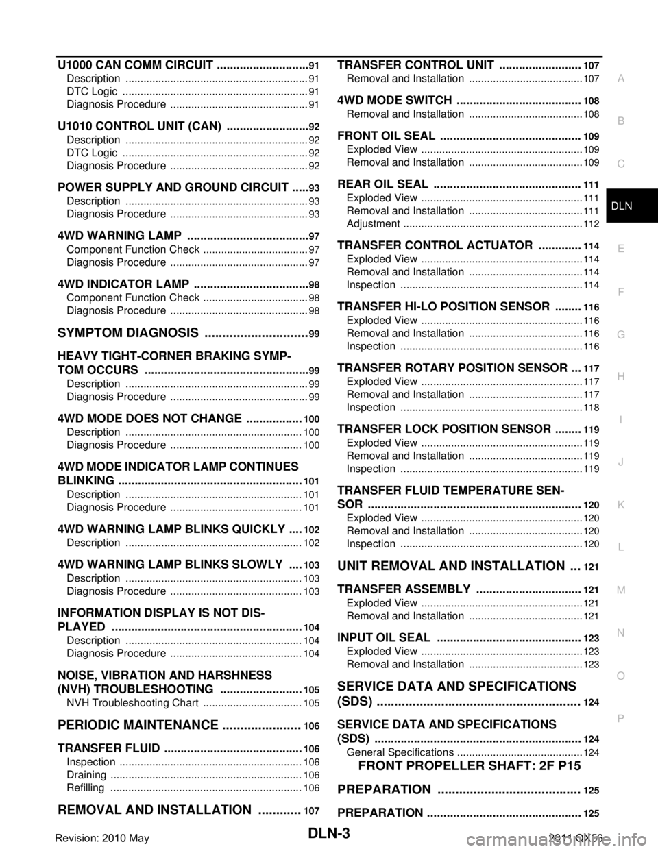
DLN-3
CEF
G H
I
J
K L
M A
B
DLN
N
O P
U1000 CAN COMM CIRCUIT ......................... ....91
Description .......................................................... ....91
DTC Logic ...............................................................91
Diagnosis Procedure ...............................................91
U1010 CONTROL UNIT (CAN) ..........................92
Description .......................................................... ....92
DTC Logic ...............................................................92
Diagnosis Procedure ...............................................92
POWER SUPPLY AND GROUND CIRCUIT ......93
Description .......................................................... ....93
Diagnosis Procedure ...............................................93
4WD WARNING LAMP ......................................97
Component Function Check ................................ ....97
Diagnosis Procedure ...............................................97
4WD INDICATOR LAMP ....................................98
Component Function Check ................................ ....98
Diagnosis Procedure ...............................................98
SYMPTOM DIAGNOSIS ..............................99
HEAVY TIGHT-CORNER BRAKING SYMP-
TOM OCCURS . .............................................. ....
99
Description .......................................................... ....99
Diagnosis Procedure ...............................................99
4WD MODE DOES NOT CHANGE ..................100
Description .......................................................... ..100
Diagnosis Procedure .............................................100
4WD MODE INDICATOR LAMP CONTINUES
BLINKING .........................................................
101
Description .......................................................... ..101
Diagnosis Procedure .............................................101
4WD WARNING LAMP BLINKS QUICKLY .....102
Description .......................................................... ..102
4WD WARNING LAMP BLINKS SLOWLY .....103
Description .......................................................... ..103
Diagnosis Procedure .............................................103
INFORMATION DISPLAY IS NOT DIS-
PLAYED ...........................................................
104
Description .......................................................... ..104
Diagnosis Procedure .............................................104
NOISE, VIBRATION AND HARSHNESS
(NVH) TROUBLESHOOTING ..........................
105
NVH Troubleshooting Chart ................................ ..105
PERIODIC MAINTENANCE .......................106
TRANSFER FLUID ......................................... ..106
Inspection ............................................................ ..106
Draining .................................................................106
Refilling .................................................................106
REMOVAL AND INSTALLATION .............107
TRANSFER CONTROL UNIT .........................107
Removal and Installation ..................................... ..107
4WD MODE SWITCH ......................................108
Removal and Installation .......................................108
FRONT OIL SEAL ...........................................109
Exploded View .......................................................109
Removal and Installation .......................................109
REAR OIL SEAL .............................................111
Exploded View .......................................................111
Removal and Installation .......................................111
Adjustment .............................................................112
TRANSFER CONTROL ACTUATOR .............114
Exploded View .......................................................114
Removal and Installation .......................................114
Inspection ..............................................................114
TRANSFER HI-LO POSITION SENSOR ........116
Exploded View .......................................................116
Removal and Installation .......................................116
Inspection ..............................................................116
TRANSFER ROTARY POSITION SENSOR ...117
Exploded View .......................................................117
Removal and Installation .......................................117
Inspection ..............................................................118
TRANSFER LOCK POSITION SENSOR ........119
Exploded View .......................................................119
Removal and Installation .......................................119
Inspection ..............................................................119
TRANSFER FLUID TEMPERATURE SEN-
SOR .................................................................
120
Exploded View .......................................................120
Removal and Installation .......................................120
Inspection ..............................................................120
UNIT REMOVAL AND INSTALLATION ....121
TRANSFER ASSEMBLY ................................121
Exploded View ..................................................... ..121
Removal and Installation .......................................121
INPUT OIL SEAL ............................................123
Exploded View .......................................................123
Removal and Installation .......................................123
SERVICE DATA AND SPECIFICATIONS
(SDS) ............... ...........................................
124
SERVICE DATA AND SPECIFICATIONS
(SDS) ...............................................................
124
General Specifications ......................................... ..124
FRONT PROPELLER SHAFT: 2F P15
PREPARATION ........ .................................
125
PREPARATION ...............................................125
Revision: 2010 May2011 QX56
Page 1808 of 5598
![INFINITI QX56 2011 Factory Service Manual
DLN-6
< PRECAUTION >[TRANSFER: ATX90A]
PRECAUTIONS
PRECAUTION
PRECAUTIONS
Precaution for Supplemental Restraint S
ystem (SRS) "AIR BAG" and "SEAT BELT
PRE-TENSIONER"
INFOID:0000000006222209
The Supp INFINITI QX56 2011 Factory Service Manual
DLN-6
< PRECAUTION >[TRANSFER: ATX90A]
PRECAUTIONS
PRECAUTION
PRECAUTIONS
Precaution for Supplemental Restraint S
ystem (SRS) "AIR BAG" and "SEAT BELT
PRE-TENSIONER"
INFOID:0000000006222209
The Supp](/manual-img/42/57033/w960_57033-1807.png)
DLN-6
< PRECAUTION >[TRANSFER: ATX90A]
PRECAUTIONS
PRECAUTION
PRECAUTIONS
Precaution for Supplemental Restraint S
ystem (SRS) "AIR BAG" and "SEAT BELT
PRE-TENSIONER"
INFOID:0000000006222209
The Supplemental Restraint System such as “A IR BAG” and “SEAT BELT PRE-TENSIONER”, used along
with a front seat belt, helps to reduce the risk or severi ty of injury to the driver and front passenger for certain
types of collision. This system includes seat belt switch inputs and dual stage front air bag modules. The SRS
system uses the seat belt switches to determine the front air bag deployment, and may only deploy one front
air bag, depending on the severity of a collision and w hether the front occupants are belted or unbelted.
Information necessary to service the system safely is included in the “SRS AIR BAG” and “SEAT BELT” of this
Service Manual.
WARNING:
• To avoid rendering the SRS inopera tive, which could increase the risk of personal injury or death in
the event of a collision that would result in air bag inflation, all maintenance must be performed by
an authorized NISS AN/INFINITI dealer.
Improper maintenance, including in correct removal and installation of the SRS, can lead to personal
injury caused by unintent ional activation of the system. For re moval of Spiral Cable and Air Bag
Module, see the “SRS AIR BAG”.
Do not use electrical test equipmen t on any circuit related to the SRS unless instructed to in this
Service Manual. SRS wiring harnesses can be identi fied by yellow and/or orange harnesses or har-
ness connectors.
PRECAUTIONS WHEN USING POWER TOOLS (AIR OR ELECTRIC) AND HAMMERS
WARNING:
When working near the Air Bag Diagnosis Sensor Unit or other Air Bag System sensors with the ignition ON or engine running, DO NOT use air or electric power tools or strike near the sensor(s)
with a hammer. Heavy vibration could activate the sensor(s) and deploy the air bag(s), possibly
causing serious injury.
When using air or electric power tools or hammers , always switch the ignition OFF, disconnect the
battery, and wait at least 3 minu tes before performing any service.
Precaution Necessary for Steering W heel Rotation after Battery Disconnect
INFOID:0000000006222210
NOTE:
Before removing and installing any control units, first tu rn the push-button ignition switch to the LOCK posi-
tion, then disconnect bot h battery cables.
After finishing work, confirm that all control unit connectors are connected properly, then re-connect both
battery cables.
Always use CONSULT-III to perform self-diagnosis as a part of each function inspection after finishing work.
If a DTC is detected, perform trouble diagnos is according to self-diagnosis results.
For vehicle with steering lock unit, if the battery is disconnected or discharged, the steering wheel will lock and
cannot be turned.
If turning the steering wheel is required with the bat tery disconnected or discharged, follow the operation pro-
cedure below before starting the repair operation.
OPERATION PROCEDURE
1. Connect both battery cables. NOTE:
Supply power using jumper cables if battery is discharged.
2. Turn the push-button ignition switch to ACC position. (At this time, the steering lock will be released.)
3. Disconnect both battery cables. The steering lock wi ll remain released with both battery cables discon-
nected and the steering wheel can be turned.
4. Perform the necessary repair operation.
Revision: 2010 May2011 QX56