Page 1694 of 5598
DLK-158
< DTC/CIRCUIT DIAGNOSIS >
TOUCH SENSOR
TOUCH SENSOR
RH
RH : Component Function CheckINFOID:0000000006225983
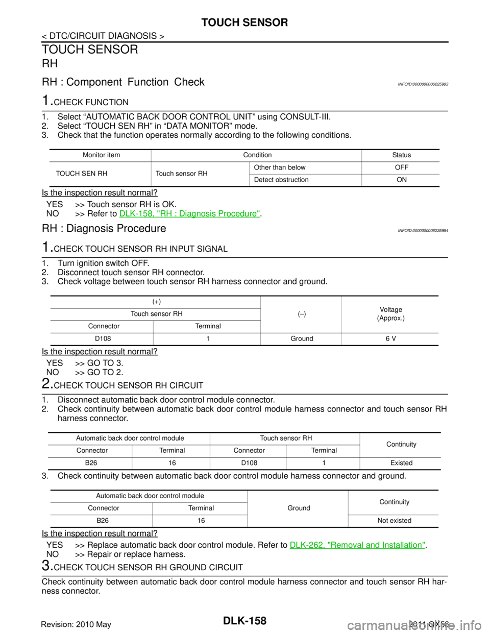
1.CHECK FUNCTION
1. Select “AUTOMATIC BACK DOOR CONTROL UNIT” using CONSULT-III.
2. Select “TOUCH SEN RH” in “DATA MONITOR” mode.
3. Check that the function operates normall y according to the following conditions.
Is the inspection result normal?
YES >> Touch sensor RH is OK.
NO >> Refer to DLK-158, "
RH : Diagnosis Procedure".
RH : Diagnosis ProcedureINFOID:0000000006225984
1.CHECK TOUCH SENSOR RH INPUT SIGNAL
1. Turn ignition switch OFF.
2. Disconnect touch sensor RH connector.
3. Check voltage between touch sensor RH harness connector and ground.
Is the inspection result normal?
YES >> GO TO 3.
NO >> GO TO 2.
2.CHECK TOUCH SENSOR RH CIRCUIT
1. Disconnect automatic back door control module connector.
2. Check continuity between automatic back door c ontrol module harness connector and touch sensor RH
harness connector.
3. Check continuity between automatic back door control module harness connector and ground.
Is the inspection result normal?
YES >> Replace automatic back door control module. Refer to DLK-262, "Removal and Installation".
NO >> Repair or replace harness.
3.CHECK TOUCH SENSOR RH GROUND CIRCUIT
Check continuity between automatic back door cont rol module harness connector and touch sensor RH har-
ness connector.
Monitor item Condition Status
TOUCH SEN RH Touch sensor RH Other than below OFF
Detect obstruction ON
(+)
(–)Vol tag e
(Approx.)
Touch sensor RH
Connector Terminal D108 1 Ground 6 V
Automatic back door control module Touch sensor RH Continuity
Connector Terminal Connector Terminal
B26 16 D108 1 Existed
Automatic back door control module GroundContinuity
Connector Terminal
B26 16 Not existed
Revision: 2010 May2011 QX56
Page 1695 of 5598
TOUCH SENSORDLK-159
< DTC/CIRCUIT DIAGNOSIS >
C
DE
F
G H
I
J
L
M A
B
DLK
N
O P
Is the inspection result normal?
YES >> GO TO 4.
NO >> Repair or replace harness.
4.CHECK TOUCH SENSOR RH
Refer to DLK-159, "
RH : Component Inspection".
Is the inspection result normal?
YES >> GO TO 5.
NO >> Replace touch sensor RH.
5.CHECK INTERMITTENT INCIDENT
Refer to GI-40, "
Intermittent Incident".
>> INSPECTION END
RH : Component InspectionINFOID:0000000006225985
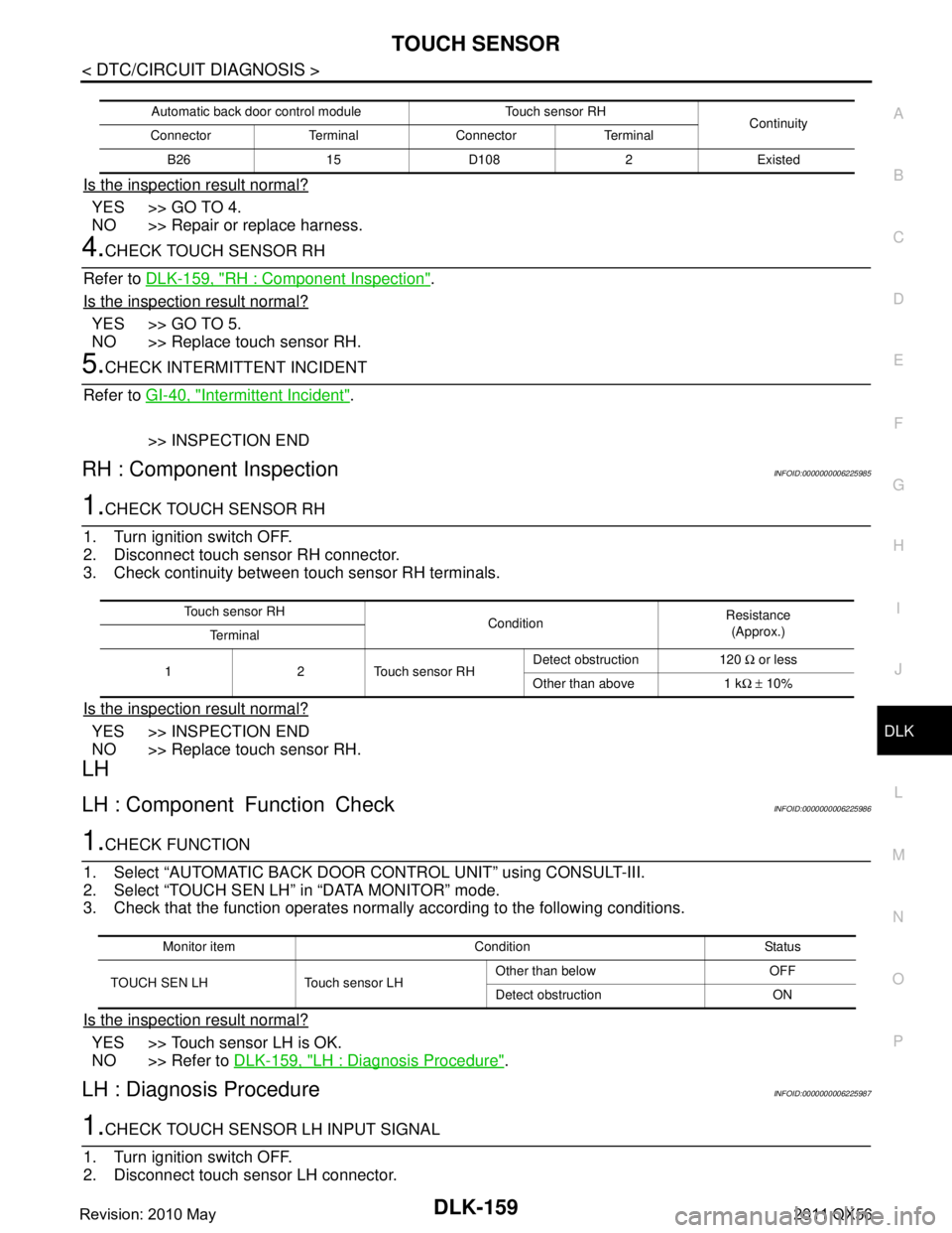
1.CHECK TOUCH SENSOR RH
1. Turn ignition switch OFF.
2. Disconnect touch sensor RH connector.
3. Check continuity between touch sensor RH terminals.
Is the inspection result normal?
YES >> INSPECTION END
NO >> Replace touch sensor RH.
LH
LH : Component Function CheckINFOID:0000000006225986
1.CHECK FUNCTION
1. Select “AUTOMATIC BACK DOOR CONTROL UNIT” using CONSULT-III.
2. Select “TOUCH SEN LH” in “DATA MONITOR” mode.
3. Check that the function operates normall y according to the following conditions.
Is the inspection result normal?
YES >> Touch sensor LH is OK.
NO >> Refer to DLK-159, "
LH : Diagnosis Procedure".
LH : Diagnosis ProcedureINFOID:0000000006225987
1.CHECK TOUCH SENSOR LH INPUT SIGNAL
1. Turn ignition switch OFF.
2. Disconnect touch sensor LH connector.
Automatic back door control module Touch sensor RH Continuity
Connector Terminal Connector Terminal
B26 15 D108 2 Existed
Touch sensor RH ConditionResistance
(Approx.)
Te r m i n a l
1 2 Touch sensor RH Detect obstruction 120
Ω or less
Other than above 1 k Ω ± 10%
Monitor item Condition Status
TOUCH SEN LH Touch sensor LH Other than below OFF
Detect obstruction ON
Revision: 2010 May2011 QX56
Page 1696 of 5598
DLK-160
< DTC/CIRCUIT DIAGNOSIS >
TOUCH SENSOR
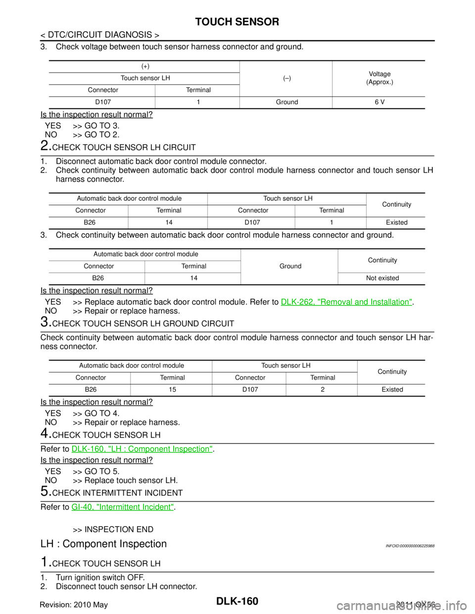
3. Check voltage between touch sensor harness connector and ground.
Is the inspection result normal?
YES >> GO TO 3.
NO >> GO TO 2.
2.CHECK TOUCH SENSOR LH CIRCUIT
1. Disconnect automatic back door control module connector.
2. Check continuity between automatic back door c ontrol module harness connector and touch sensor LH
harness connector.
3. Check continuity between automatic back door control module harness connector and ground.
Is the inspection result normal?
YES >> Replace automatic back door control module. Refer to DLK-262, "Removal and Installation".
NO >> Repair or replace harness.
3.CHECK TOUCH SENSOR LH GROUND CIRCUIT
Check continuity between automatic back door contro l module harness connector and touch sensor LH har-
ness connector.
Is the inspection result normal?
YES >> GO TO 4.
NO >> Repair or replace harness.
4.CHECK TOUCH SENSOR LH
Refer to DLK-160, "
LH : Component Inspection".
Is the inspection result normal?
YES >> GO TO 5.
NO >> Replace touch sensor LH.
5.CHECK INTERMITTENT INCIDENT
Refer to GI-40, "
Intermittent Incident".
>> INSPECTION END
LH : Component InspectionINFOID:0000000006225988
1.CHECK TOUCH SENSOR LH
1. Turn ignition switch OFF.
2. Disconnect touch sensor LH connector.
(+)
(–)Voltag e
(Approx.)
Touch sensor LH
Connector Terminal D107 1 Ground 6 V
Automatic back door control module Touch sensor LH Continuity
Connector Terminal Connector Terminal
B26 14 D107 1 Existed
Automatic back door control module GroundContinuity
Connector Terminal
B26 14 Not existed
Automatic back door control module Touch sensor LH Continuity
Connector Terminal Connector Terminal
B26 15 D107 2 Existed
Revision: 2010 May2011 QX56
Page 1697 of 5598
TOUCH SENSORDLK-161
< DTC/CIRCUIT DIAGNOSIS >
C
DE
F
G H
I
J
L
M A
B
DLK
N
O P
3. Check continuity between touch sensor LH terminals.
Is the inspection result normal?
YES >> INSPECTION END
NO >> Replace touch sensor LH.
Touch sensor LH ConditionResistance
(Approx.)
Te r m i n a l
1 2 Touch sensor LH Detect obstruction 120
Ω or less
Other than above 1 k Ω ± 10%
Revision: 2010 May2011 QX56
Page 1721 of 5598
KEY REMINDER FUNCTION DOES NOT OPERATEDLK-185
< SYMPTOM DIAGNOSIS >
C
DE
F
G H
I
J
L
M A
B
DLK
N
O P
KEY REMINDER FUNCTION DOES NOT OPERATE
Diagnosis ProcedureINFOID:0000000006226023
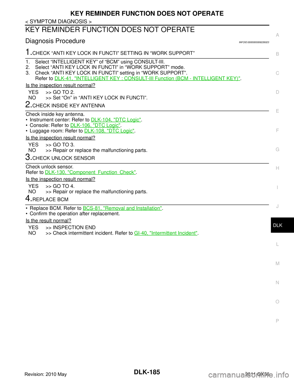
1.CHECK “ANTI KEY LOCK IN FUNCT I” SETTING IN “WORK SUPPORT”
1. Select “INTELLIGENT KEY” of “BCM” using CONSULT-III.
2. Select “ANTI KEY LOCK IN F UNCTI” in “WORK SUPPORT” mode.
3. Check “ANTI KEY LOCK IN FUNCT I” setting in “WORK SUPPORT”.
Refer to DLK-41, "
INTELLIGENT KEY : CONSULT-III Function (BCM - INTELLIGENT KEY)".
Is the inspection result normal?
YES >> GO TO 2.
NO >> Set “On” in “ANTI KEY LOCK IN FUNCTI”.
2.CHECK INSIDE KEY ANTENNA
Check inside key antenna.
Instrument center: Refer to DLK-104, "
DTC Logic".
Console: Refer to DLK-106, "
DTC Logic".
Luggage room: Refer to DLK-108, "
DTC Logic".
Is the inspection result normal?
YES >> GO TO 3.
NO >> Repair or replace the malfunctioning parts.
3.CHECK UNLOCK SENSOR
Check unlock sensor.
Refer to DLK-130, "
ComponentFunctionCheck".
Is the inspection result normal?
YES >> GO TO 4.
NO >> Repair or replace the malfunctioning parts.
4.REPLACE BCM
Replace BCM. Refer to BCS-81, "
Removal and Installation".
Confirm the operation after replacement.
Is the result normal?
YES >> INSPECTION END
NO >> Check intermittent incident. Refer to GI-40, "
Intermittent Incident".
Revision: 2010 May2011 QX56
Page 1734 of 5598
DLK-198
< SYMPTOM DIAGNOSIS >
AUTOMATIC BACK DOOR OPERATION DOES NOT OPERATE
AUTOMATIC BACK DOOR OPERATION DOES NOT OPERATE
ALL SWITCHES
ALL SWITCHES : DescriptionINFOID:0000000006226037
Automatic back door open/close function does not operate using all switches.
NOTE:
Automatic back door open/close operation condition is ex tremely complicated, during operating confirmations,
reconfirm the list above twice in order to ensure proper operation. Refer to DLK-31, "
System Description".
ALL SWITCHES : Diagnosis ProcedureINFOID:0000000006226038
1.CHECK DTC WITH AUTOMATIC BACK DOOR CONTROL MODULE
Check that DTC is not detected with automatic back door control module.
Is the inspection result normal?
YES >> GO TO 2.
NO >> Perform trouble diagnosis relevant to DTC indicated.
2.CHECK BACK DOOR AUTO CLOSURE FUNCTION
Check back door auto closure function.
Is the inspection result normal?
YES >> GO TO 3.
NO >> Refer to DLK-201, "
OPEN/CLOSURE FUNCTION : Diagnosis Procedure".
3.CHECK POWER SUPPLY AND GROUND CIRCUIT
Check automatic back door control module power supply and ground circuit.
Refer to DLK-116, "
AUTOMATIC BACK DOOR CONTROL UNIT : Diagnosis Procedure".
Is the inspection result normal?
YES >> GO TO 4.
NO >> Repair or replace the malfunctioning parts.
4.CHECK GROUND CIRCUIT
Check automatic back door control module ground circuit.
Refer to DLK-165, "
ComponentFunctionCheck".
Is the inspection result normal?
YES >> GO TO 5.
NO >> Repair or replace the malfunctioning parts.
5.CHECK TOUCH SENSOR LH
Check touch sensor LH.
Refer to DLK-159, "
LH : ComponentFunctionCheck".
Is the inspection result normal?
YES >> GO TO 6.
NO >> Repair or replace the malfunctioning parts.
6.CHECK TOUCH SENSOR RH
Check touch sensor RH.
Refer to DLK-158, "
RH : ComponentFunctionCheck".
Is the inspection result normal?
YES >> GO TO 7.
NO >> Repair or replace the malfunctioning parts.
7.REPLACE AUTOMATIC BACK DOOR CONTROL MODULE
1. Replace automatic back door control module. Refer to DLK-262, "
Removal and Installation".
2. Confirm the operation after replacement.
Is the result normal?
YES >> INSPECTION END
Revision: 2010 May2011 QX56
Page 1743 of 5598

AUTOMATIC BACK DOOR ANTI-PINCH FUNCTION DOES NOT OPERATE
DLK-207
< SYMPTOM DIAGNOSIS >
C
D E
F
G H
I
J
L
M A
B
DLK
N
O P
AUTOMATIC BACK DOOR ANTI-PINCH FUNCTION DOES NOT OPERATE
Diagnosis ProcedureINFOID:0000000006226058
1.CHECK POWER SUPPLY AND GROUND CIRCUIT
Check automatic back door control module power supply and ground circuit.
Refer to DLK-116, "
AUTOMATIC BACK DOOR CONTROL UNIT : Diagnosis Procedure".
Is the inspection result normal?
YES >> GO TO 2.
NO >> Repair or replace the malfunctioning parts.
2.CHECK TOUCH SENSOR LH
Check touch sensor LH.
Refer to DLK-159, "
LH : ComponentFunctionCheck".
Is the inspection result normal?
YES >> GO TO 3.
NO >> Repair or replace the malfunctioning parts.
3.CHECK TOUCH SENSOR RH
Check touch sensor RH.
Refer to DLK-158, "
RH : ComponentFunctionCheck".
Is the inspection result normal?
YES >> GO TO 4.
NO >> Repair or replace the malfunctioning parts.
4.REPLACE AUTOMATIC BACK DOOR CONTROL MODULE
1. Replace automatic back door control module. Refer to DLK-262, "
Removal and Installation".
2. Confirm the operation after replacement.
Is the result normal?
YES >> INSPECTION END
NO >> Check intermittent incident. Refer to GI-40, "
Intermittent Incident".
Revision: 2010 May2011 QX56
Page 1756 of 5598
DLK-220
< REMOVAL AND INSTALLATION >
RADIATOR CORE SUPPORT
RADIATOR CORE SUPPORT
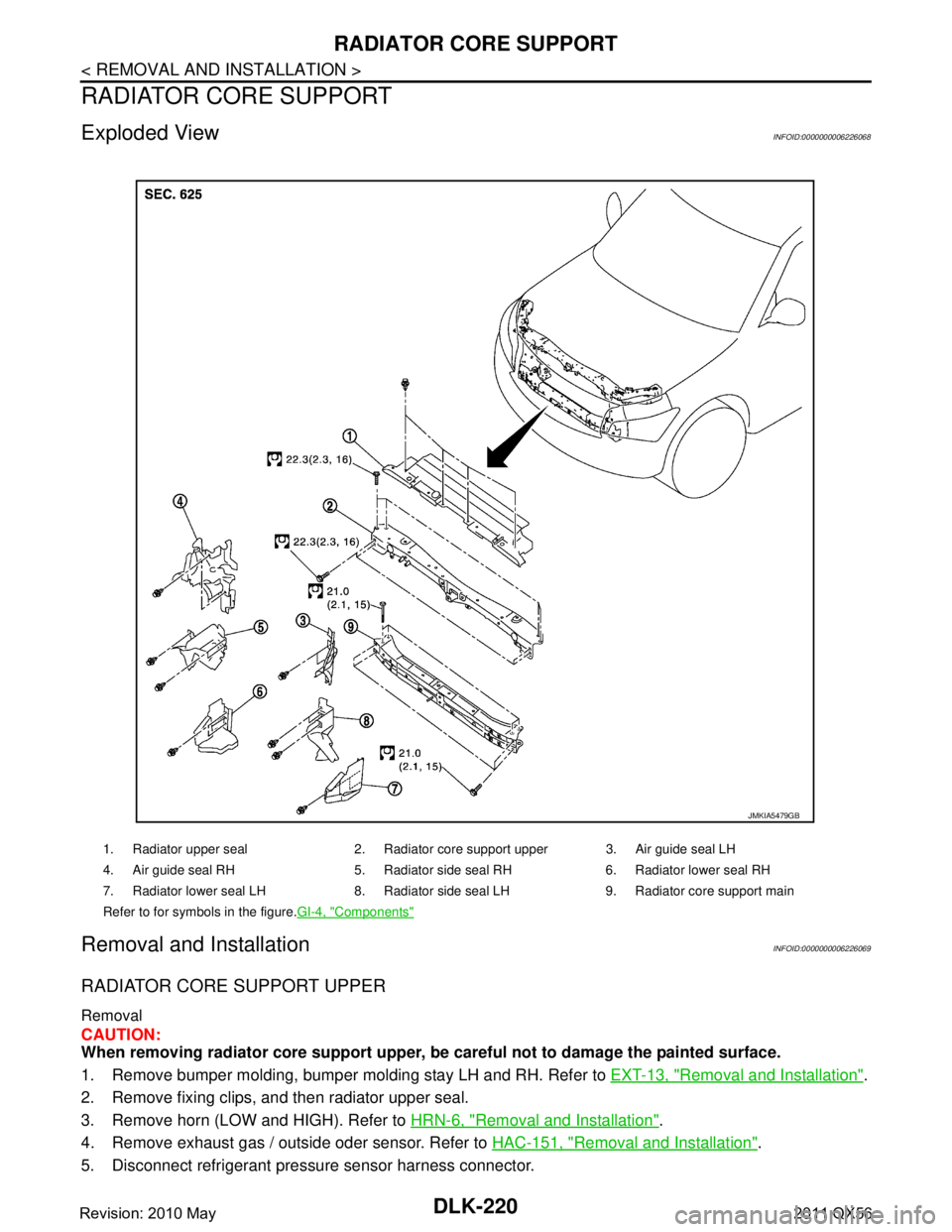
Exploded ViewINFOID:0000000006226068
Removal and InstallationINFOID:0000000006226069
RADIATOR CORE SUPPORT UPPER
Removal
CAUTION:
When removing radiator core support upper, be careful not to damage the painted surface.
1. Remove bumper molding, bumper molding stay LH and RH. Refer to EXT-13, "
Removal and Installation".
2. Remove fixing clips, and then radiator upper seal.
3. Remove horn (LOW and HIGH). Refer to HRN-6, "
Removal and Installation".
4. Remove exhaust gas / outside oder sensor. Refer to HAC-151, "
Removal and Installation".
5. Disconnect refrigerant pressu re sensor harness connector.
1. Radiator upper seal 2. Radiator core support upper 3. Air guide seal LH
4. Air guide seal RH 5. Radiator side seal RH 6. Radiator lower seal RH
7. Radiator lower seal LH 8. Radiator side seal LH 9. Radiator core support main
Refer to for symbols in the figure.GI-4, "
Components"
JMKIA5479GB
Revision: 2010 May2011 QX56