Page 5559 of 5598

WW-40
< DTC/CIRCUIT DIAGNOSIS >
LIGHT & RAIN SENSOR
LIGHT & RAIN SENSOR
Component Function CheckINFOID:0000000006300475
1.CHECK FRONT WIPER AUTO OPERATION
1. Clean light & rain sensor detection area of windshield fully.
2. When the front wiper switch is turned to AUTO pos ition, front wiper operates once regardless of a rainy
condition.
Is front wiper (AUTO) operation normally?
YES >> Light & rain sensor circuit is normal.
NO >> Refer to WW-40, "
Diagnosis Procedure".
Diagnosis ProcedureINFOID:0000000006300476
1.CHECK LIGHT & RAIN SENSOR FUSE
1. Turn the ignition switch OFF.
2. Check that the light & rain sensor 10A fuse (#6) is not fusing.
Is the fuse fusing?
YES >> Replace the fuse after repairing the applicable circuit.
NO >> GO TO 2.
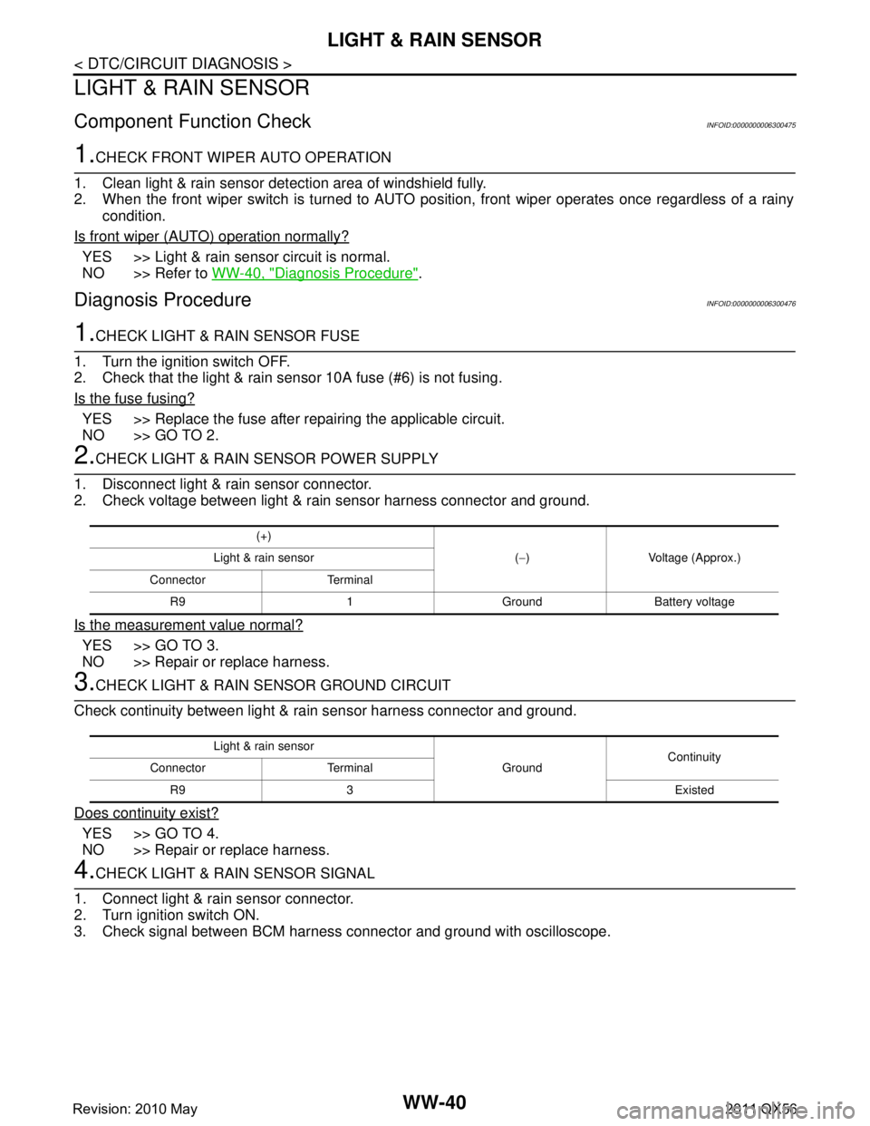
2.CHECK LIGHT & RAIN SENSOR POWER SUPPLY
1. Disconnect light & rain sensor connector.
2. Check voltage between light & rain sensor harness connector and ground.
Is the measurement value normal?
YES >> GO TO 3.
NO >> Repair or replace harness.
3.CHECK LIGHT & RAIN SENSOR GROUND CIRCUIT
Check continuity between light & ra in sensor harness connector and ground.
Does continuity exist?
YES >> GO TO 4.
NO >> Repair or replace harness.
4.CHECK LIGHT & RAIN SENSOR SIGNAL
1. Connect light & rain sensor connector.
2. Turn ignition switch ON.
3. Check signal between BCM harness connector and ground with oscilloscope.
(+)
(− ) Voltage (Approx.)
Light & rain sensor
Connector Terminal R9 1 Ground Battery voltage
Light & rain sensor GroundContinuity
Connector Terminal
R9 3 Existed
Revision: 2010 May2011 QX56
Page 5560 of 5598

LIGHT & RAIN SENSORWW-41
< DTC/CIRCUIT DIAGNOSIS >
C
DE
F
G H
I
J
K
M A
B
WW
N
O P
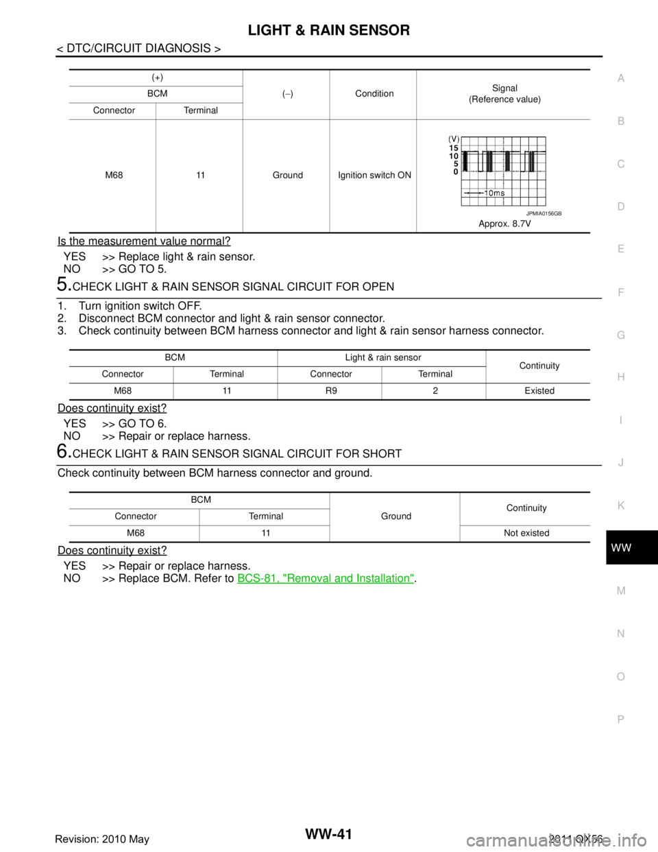
Is the measurement value normal?
YES >> Replace light & rain sensor.
NO >> GO TO 5.
5.CHECK LIGHT & RAIN SENSOR SIGNAL CIRCUIT FOR OPEN
1. Turn ignition switch OFF.
2. Disconnect BCM connector and light & rain sensor connector.
3. Check continuity between BCM harness connecto r and light & rain sensor harness connector.
Does continuity exist?
YES >> GO TO 6.
NO >> Repair or replace harness.
6.CHECK LIGHT & RAIN SENSOR SIGNAL CIRCUIT FOR SHORT
Check continuity between BCM harness connector and ground.
Does continuity exist?
YES >> Repair or replace harness.
NO >> Replace BCM. Refer to BCS-81, "
Removal and Installation".
(+)
(− ) Condition Signal
(Reference value)
BCM
Connector Terminal
M68 11 Ground Ignition switch ON Approx. 8.7V
JPMIA0156GB
BCM Light & rain sensorContinuity
Connector Terminal Connector Terminal
M68 11 R9 2 Existed
BCM GroundContinuity
Connector Terminal
M68 11 Not existed
Revision: 2010 May2011 QX56
Page 5568 of 5598

WIPER AND WASHER SYSTEM SYMPTOMSWW-49
< SYMPTOM DIAGNOSIS >
C
DE
F
G H
I
J
K
M A
B
WW
N
O P
SYMPTOM DIAGNOSIS
WIPER AND WASHER SYSTEM SYMPTOMS
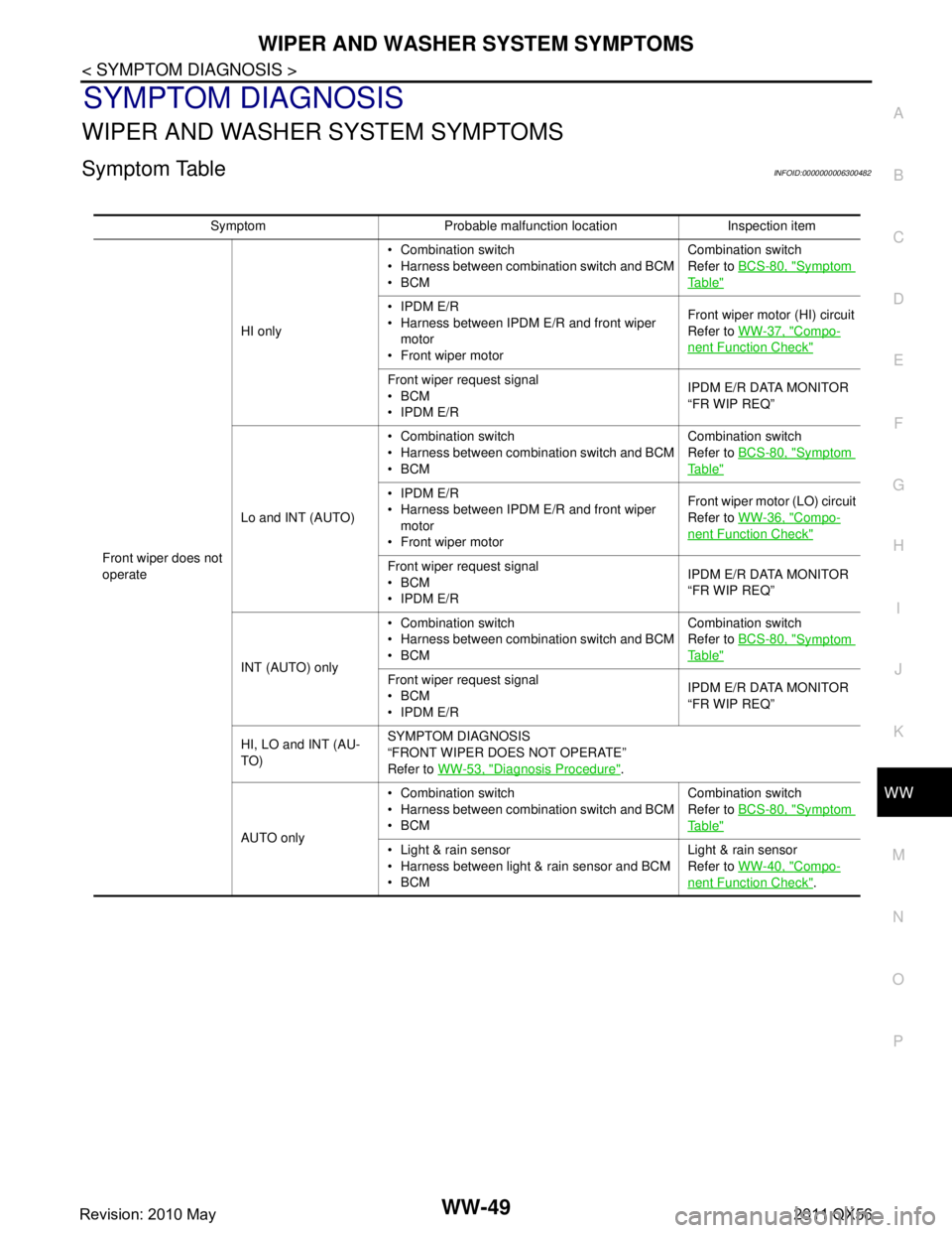
Symptom TableINFOID:0000000006300482
Symptom Probable malfunction location Inspection item
Front wiper does not
operate HI only
Combination switch
Harness between combination switch and BCM
BCM
Combination switch
Refer to
BCS-80, "
Symptom
Ta b l e"
IPDM E/R
Harness between IPDM E/R and front wiper
motor
Front wiper motor Front wiper motor (HI) circuit
Refer to
WW-37, "
Compo-
nent Function Check"
Front wiper request signal
BCM
IPDM E/R IPDM E/R DATA MONITOR
“FR WIP REQ”
Lo and INT (AUTO) Combination switch
Harness between combination switch and BCM
BCM
Combination switch
Refer to
BCS-80, "
Symptom
Ta b l e"
IPDM E/R
Harness between IPDM E/R and front wiper
motor
Front wiper motor Front wiper motor (LO) circuit
Refer to
WW-36, "
Compo-
nent Function Check"
Front wiper request signal
BCM
IPDM E/R IPDM E/R DATA MONITOR
“FR WIP REQ”
INT (AUTO) only Combination switch
Harness between combination switch and BCM
BCM
Combination switch
Refer to
BCS-80, "
Symptom
Ta b l e"
Front wiper request signal
BCM
IPDM E/R IPDM E/R DATA MONITOR
“FR WIP REQ”
HI, LO and INT (AU-
TO) SYMPTOM DIAGNOSIS
“FRONT WIPER DOES NOT OPERATE”
Refer to
WW-53, "
Diagnosis Procedure".
AUTO only Combination switch
Harness between combination switch and BCM
BCM
Combination switch
Refer to
BCS-80, "
Symptom
Ta b l e"
Light & rain sensor
Harness between light & rain sensor and BCM
BCM Light & rain sensor
Refer to
WW-40, "
Compo-
nent Function Check".
Revision: 2010 May2011 QX56
Page 5591 of 5598
WW-72
< REMOVAL AND INSTALLATION >
LIGHT & RAIN SENSOR
LIGHT & RAIN SENSOR
Exploded ViewINFOID:0000000006220417
CAUTION:
When the light & rain sensor is removed from windshield, the light & rain sensor cannot be re-used.
Removal and InstallationINFOID:0000000006220418
REMOVAL
1. Disengage light & rain sensor cover fixing pawls with a remover tool, and then remove rain senor cover.
2. Disconnect light & rain sensor connector.
3. Disengage both sides metal spring clips, and remove the light & rain sensor from the windshield.
INSTALLATION
Note the following items, and then install in the reverse order of removal.
CAUTION:
Surface of windshield should be cleaned.
Never touch gel/adhesive of new part.
Lock the metal spring clips and inst all the light & rain sensor securely.
1. Light & rain sensor connector 2. Light & rain sensor cover 3. Light & rain sensor
A. Metal spring clip
: Pawl
: Do not reuse
JMLIA0941ZZ
Revision: 2010 May2011 QX56