2011 INFINITI QX56 sensor
[x] Cancel search: sensorPage 5521 of 5598

WW-2
FRONT WIPER MOTOR GROUND CIRCUIT ...39
Diagnosis Procedure ..............................................39
LIGHT & RAIN SENSOR ...................................40
Component Function Check ................................ ...40
Diagnosis Procedure ..............................................40
WASHER SWITCH ............................................42
Component Inspection ......................................... ...42
REAR WIPER MOTOR CIRCUIT ......................43
Component Function Check ................................ ...43
Diagnosis Procedure ..............................................43
REAR WIPER AUTO STOP SIGNAL CIRCUIT
...
45
Component Function Check ................................ ...45
Diagnosis Procedure ..............................................45
HEADLAMP WASHER RELAY .........................46
Component Inspection ......................................... ...46
HEADLAMP WASHER CIRCUIT ......................47
Component Function Check ................................ ...47
Diagnosis Procedure ..............................................47
SYMPTOM DIAGNOSIS .............................49
WIPER AND WASHER SYSTEM SYMPTOMS
...
49
Symptom Table ................................................... ...49
NORMAL OPERATING CONDITION ................52
Description ........................................................... ...52
FRONT WIPER DOES NOT OPERATE ............53
Description ........................................................... ...53
Diagnosis Procedure ..............................................53
REMOVAL AND INSTALLATION ...............55
HEADLAMP WASHER NOZZLE AND TUBE ...55
Exploded View ..................................................... ...55
Hydraulic Layout .....................................................55
Removal and Installation ........................................56
Inspection ...............................................................56
WASHER TANK ............................................. ...58
Exploded View ..................................................... ...58
Removal and Installation ........................................58
WASHER PUMP ................................................60
Exploded View ..................................................... ...60
Removal and Installation .........................................60
HEADLAMP WASHER PUMP ..........................61
Exploded View ..................................................... ...61
Removal and Installation .........................................61
WASHER LEVEL SWITCH ...............................62
Removal and Installation ...................................... ...62
FRONT WASHER NOZZLE AND TUBE ...........63
Exploded View ..................................................... ...63
Hydraulic Layout .....................................................63
Removal and Installation .........................................64
Inspection and Adjustment ......................................64
FRONT WIPER ARM .........................................66
Exploded View ..................................................... ...66
Removal and Installation .........................................66
Adjustment ..............................................................66
FRONT WIPER BLADE .....................................68
Exploded View ..................................................... ...68
Removal and Installation .........................................68
Replacement ...........................................................68
FRONT WIPER DRIVE ASSEMBLY .................70
Exploded View ..................................................... ...70
Removal and Installation .........................................70
Disassembly and Assembly ....................................71
LIGHT & RAIN SENSOR ...................................72
Exploded View ..................................................... ...72
Removal and Installation .........................................72
WIPER AND WASHER SWITCH ......................73
Exploded View ..................................................... ...73
REAR WIPER ARM ...........................................74
Exploded View ..................................................... ...74
Removal and Installation .........................................74
Adjustment ..............................................................74
REAR WIPER MOTOR ......................................76
Exploded View ..................................................... ...76
Removal and Installation .........................................76
REAR WASHER NOZZLE AND TUBE .............77
Hydraulic Layout .................................................. ...77
Removal and Installation .........................................77
Inspection and Adjustment ......................................78
Revision: 2010 May2011 QX56
Page 5522 of 5598

PRECAUTIONSWW-3
< PRECAUTION >
C
DE
F
G H
I
J
K
M A
B
WW
N
O P
PRECAUTION
PRECAUTIONS
Precaution for Supplemental Restraint System (SRS) "AIR BAG" and "SEAT BELT
PRE-TENSIONER"
INFOID:0000000006349780
The Supplemental Restraint System such as “A IR BAG” and “SEAT BELT PRE-TENSIONER”, used along
with a front seat belt, helps to reduce the risk or severi ty of injury to the driver and front passenger for certain
types of collision. This system includes seat belt switch inputs and dual stage front air bag modules. The SRS
system uses the seat belt switches to determine the front air bag deployment, and may only deploy one front
air bag, depending on the severity of a collision and whether the front occupants are belted or unbelted.
Information necessary to service the system safely is included in the “SRS AIR BAG” and “SEAT BELT” of this
Service Manual.
WARNING:
• To avoid rendering the SRS inoper ative, which could increase the risk of personal injury or death in
the event of a collision that would result in air ba g inflation, all maintenance must be performed by
an authorized NISSAN/INFINITI dealer.
Improper maintenance, including in correct removal and installation of the SRS, can lead to personal
injury caused by unintentional act ivation of the system. For removal of Spiral Cable and Air Bag
Module, see the “SRS AIR BAG”.
Do not use electrical test equipm ent on any circuit related to the SRS unless instructed to in this
Service Manual. SRS wiring harnesses can be identi fied by yellow and/or orange harnesses or har-
ness connectors.
PRECAUTIONS WHEN USING POWER TOOLS (AIR OR ELECTRIC) AND HAMMERS
WARNING:
When working near the Air Bag Diagnosis Sensor Unit or other Air Bag System sensors with the
ignition ON or engine running, DO NOT use air or electric power tools or strike near the sensor(s)
with a hammer. Heavy vibration could activate the sensor(s) and deploy the air bag(s), possibly
causing serious injury.
When using air or electric power tools or hammers , always switch the ignition OFF, disconnect the
battery, and wait at least 3 minutes before performing any service.
Precaution Necessary for Steering Wh eel Rotation after Battery Disconnect
INFOID:0000000006300446
NOTE:
Before removing and installing any control units, first tu rn the push-button ignition switch to the LOCK posi-
tion, then disconnect both battery cables.
After finishing work, confirm that all control unit connectors are connected properly, then re-connect both
battery cables.
Always use CONSULT-III to perform self-diagnosis as a part of each function inspection after finishing work.
If a DTC is detected, perform trouble diagnos is according to self-diagnosis results.
For vehicle with steering lock unit, if the battery is disconnected or discharged, the steering wheel will lock and
cannot be turned.
If turning the steering wheel is required with the batte ry disconnected or discharged, follow the operation pro-
cedure below before starting the repair operation.
OPERATION PROCEDURE
1. Connect both battery cables. NOTE:
Supply power using jumper cables if battery is discharged.
2. Turn the push-button ignition switch to ACC position. (At this time, the steering lock will be released.)
3. Disconnect both battery cables. The steering lock wil l remain released with both battery cables discon-
nected and the steering wheel can be turned.
4. Perform the necessary repair operation.
Revision: 2010 May2011 QX56
Page 5524 of 5598

COMPONENT PARTSWW-5
< SYSTEM DESCRIPTION >
C
DE
F
G H
I
J
K
M A
B
WW
N
O P
SYSTEM DESCRIPTION
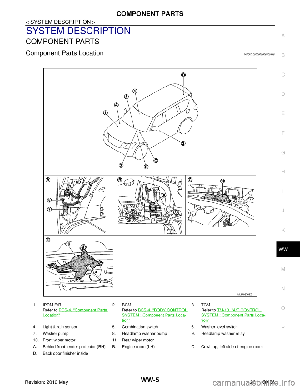
COMPONENT PARTS
Component Parts LocationINFOID:0000000006300448
1. IPDM E/R Refer to PCS-4, "
Component Parts
Location"
2. BCM
Refer to BCS-4, "
BODY CONTROL
SYSTEM : Component Parts Loca-
tion"
3. TCM
Refer to TM-10, "
A/T CONTROL
SYSTEM : Componen t Parts Loca-
tion"
4. Light & rain sensor 5. Combination switch 6. Washer level switch
7. Washer pump 8. Headlamp washer pump 9. Headlamp washer relay
10. Front wiper motor 11. Rear wiper motor
A. Behind front fender protector (RH) B. Engine room (LH) C. Cowl top, left side of engine room
D. Back door finisher inside
JMLIA0976ZZ
Revision: 2010 May2011 QX56
Page 5525 of 5598

WW-6
< SYSTEM DESCRIPTION >
COMPONENT PARTS
Component Description
INFOID:0000000006300449
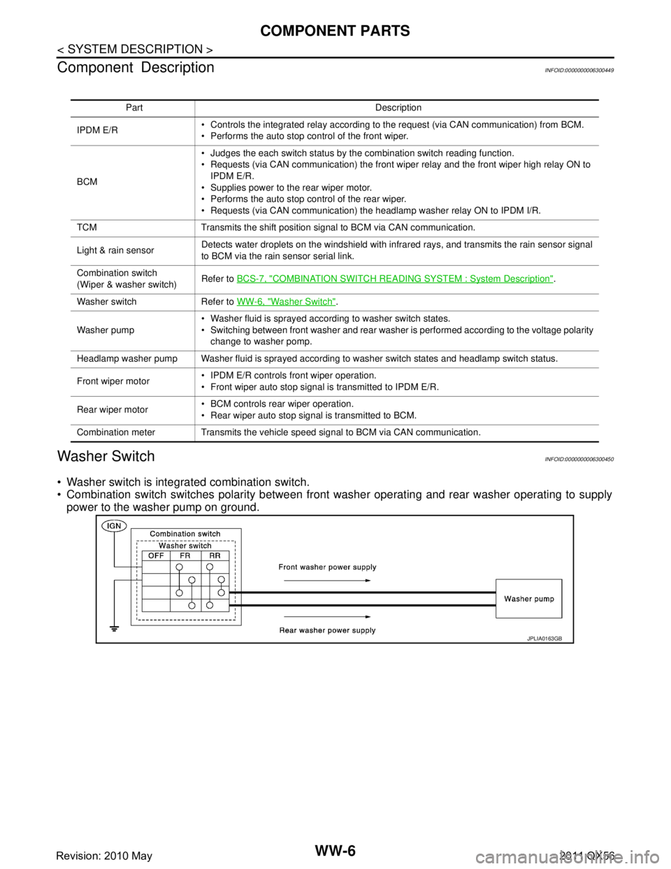
Washer SwitchINFOID:0000000006300450
Washer switch is integrated combination switch.
Combination switch switches polarity between front washer operating and rear washer operating to supply
power to the washer pump on ground.
Part Description
IPDM E/R Controls the integrated relay according to the request (via CAN communication) from BCM.
Performs the auto stop control of the front wiper.
BCM Judges the each switch status by the combination switch reading function.
Requests (via CAN communication) the front wiper relay and the front wiper high relay ON to
IPDM E/R.
Supplies power to the rear wiper motor.
Performs the auto stop control of the rear wiper.
Requests (via CAN communication) the headlamp washer relay ON to IPDM I/R.
TCM Transmits the shift position signal to BCM via CAN communication.
Light & rain sensor Detects water droplets on the windshield with infrared rays, and transmits the rain sensor signal
to BCM via the rain sensor serial link.
Combination switch
(Wiper & washer switch) Refer to
BCS-7, "
COMBINATION SWITCH READING S YSTEM : System Description".
Washer switch Refer to WW-6, "
Washer Switch".
Washer pump Washer fluid is sprayed according to washer switch states.
Switching between front washer and rear washer is performed according to the voltage polarity
change to washer pomp.
Headlamp washer pump Washer fluid is sprayed according to washer switch states and headlamp switch status.
Front wiper motor IPDM E/R controls front wiper operation.
Front wiper auto stop signal is transmitted to IPDM E/R.
Rear wiper motor BCM controls rear wiper operation.
Rear wiper auto stop signal is transmitted to BCM.
Combination meter Transmits the vehicle speed signal to BCM via CAN communication.
JPLIA0163GB
Revision: 2010 May2011 QX56
Page 5527 of 5598

WW-8
< SYSTEM DESCRIPTION >
SYSTEM
FRONT WIPER AUTO OPERATION
Rain Detection
Rain level and sensor conditions are detected by light & rain sensor.
BCM transmits the vehicle conditions (vehicle speed, front wiper condition, rain sensor sensitivity setting,
etc.) to the light & rain sensor via the rain sensor serial link.
Light & rain sensor judges a wiping speed for front wi per by rain condition and the vehicle conditions. And it
transmits the wiping speed request signal to t he BCM via the rain sensor serial link.
Auto Wiping Operation
BCM receives the wiping speed request signal from the light & rain sensor via the rain sensor serial link.
BCM controls front wiper operation according to t he wiping speed request signals. And it transmits the front
wiper request signals (LO or HI) to the IPDM E/R via CAN communication line.
Front wiper AUTO operating condition
- Ignition switch ON
- Front wiper switch AUTO
NOTE:
When the front wiper switch is turned to AUTO positi on, front wiper operates once regardless of rainy condi-
tions.
Rain Sensor Sensitivity Setting
BCM determines rain sensor sensitivity according to wiper volume dial position.
NOTE:
When the wiper volume dial position is turned up by 1 level under front wiper AUTO operating condition, front
wiper operates once.
Splash mode operation
Front wiper is operated at HI regardl ess of the wiper volume adjustment position, when water drops are instan-
taneously sprayed over the windshield glass due to wate r splash from oncoming vehicles or other causes.
After that, AUTO operation is performed depending on the amount of water drops.
SPLASH MODE OPERATION CONDITIONS Front wiper switch AUTO
Ignition switch ON
NOTE:
Splash mode is not operated and auto wiping operati on is performed, while the vehicle is stopped.
FRONT WIPER AUTO STOP OPERATION
BCM stops transmitting the front wiper request signal when the front wiper switch is turned OFF.
IPDM E/R detects the front wiper stop position signal from the front wiper motor and detects the front wiper
motor position (stop position/except stop position).
Wiper volume dial position Sensitivity
1 High sensitivity
2
3 Medium−high sensitivity
4
5 Low−medium sensitivity
6
7 Low sensitivity
Revision: 2010 May2011 QX56
Page 5529 of 5598

WW-10
< SYSTEM DESCRIPTION >
SYSTEM
IPDM E/R detects front wiper stop position by a front wiper stop position signal.
When a front wiper stop position signal is in the conditi ons listed below, IPDM E/R stops power supply to wiper
after repeating a front wiper 10 seconds activation and 20 seconds stop five times.
NOTE:
This operation status can be confirmed on the IPDM E/ R “Data Monitor” that displays “BLOCK” for the item
“WIP PROT” while the wiper is stopped.
BCM
BCM detects the rain sensor serial link error and the light & rain sensor malfunction.
BCM controls the following fail-safe when light & rain sensor has a malfunction.
Fail-safe Control
Front wiper control
- Front wiper switch AUTO and sensing rain drop: The c ondition just before the activation of fail-safe is main-
tained until the front wiper switch is turned OFF.
- Front wiper switch AUTO and not sensing rain drop: Front wiper is LO operation until the front wiper switch is
turned off.
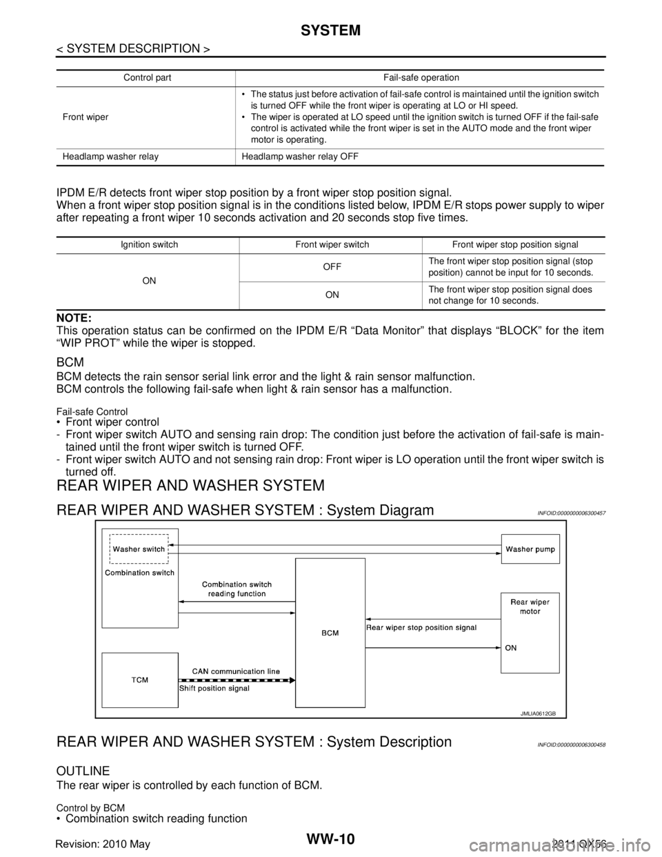
REAR WIPER AND WASHER SYSTEM
REAR WIPER AND WASHER SYSTEM : System DiagramINFOID:0000000006300457
REAR WIPER AND WASHER S YSTEM : System DescriptionINFOID:0000000006300458
OUTLINE
The rear wiper is controlled by each function of BCM.
Control by BCM
Combination switch reading function
Control part Fail-safe operation
Front wiper The status just before activation of fail-safe control is maintained until the ignition switch
is turned OFF while the front wiper is operating at LO or HI speed.
The wiper is operated at LO speed until the ignition switch is turned OFF if the fail-safe
control is activated while the front wiper is set in the AUTO mode and the front wiper
motor is operating.
Headlamp washer relay Headlamp washer relay OFF
Ignition switch Front wiper switch Front wiper stop position signal
ON OFF
The front wiper stop position signal (stop
position) cannot be input for 10 seconds.
ON The front wiper stop position signal does
not change for 10 seconds.
JMLIA0612GB
Revision: 2010 May2011 QX56
Page 5531 of 5598

WW-12
< SYSTEM DESCRIPTION >
SYSTEM
- Rear washer switch ON (0.4 second or more)
The washer pump is grounded through the combination switch with the rear washer switch ON.
REAR WIPER OPERATION LINKED WITH REVERSE (WITH RAIN SENSOR)
BCM controls rear wiper to operate once according to the conditions of rear wiper operation linked with
reverse.
Condition of rear wiper operation linked with reverse - Ignition switch ON
- Front wiper switch: LO, HI or AUTO, and the front wiper auto operation ON judgement.
- Rear wiper switch OFF
- Selector lever “R”
TCM transmits the shift position signal to BCM thr ough the CAN communication line when the selector lever
is shifted to "R".
BCM supplies power to the rear wiper motor when receiving the shift position signal.
REAR WIPER OPERATION LINKED WITH REVERSE (WITHOUT RAIN SENSOR)
BCM controls rear wiper to operate once according to the conditions of rear wiper operation linked with
reverse.
Condition of rear wiper operation linked with reverse
- Ignition switch ON
- Front wiper switch: LO, HI or INT.
- Rear wiper switch OFF
- Selector lever “R”
TCM transmits the shift position signal to BCM thr ough the CAN communication line when the selector lever
is shifted to "R".
BCM supplies power to the rear wiper motor when receiving the shift position signal.
REAR WIPER DROP WIPE OPERATION
BCM controls the rear wiper to operate once acco rding to the rear wiper drop wipe operating condition.
Rear wiper drop wipe operating condition- Ignition switch ON
- Rear wiper switch OFF
- Rear washer switch OFF
BCM controls the rear wiper so that it operates once approximately three seconds later after the washer
interlocking operation of the rear wiper.
REAR WIPER AND WASHER SYSTEM : Fail SafeINFOID:0000000006300459
REAR WIPER MOTOR PROTECTION
BCM detects the rear wiper stopping position ac cording to the rear wiper auto stop signal.
When the rear wiper auto stop signal does not change more than 5 seconds while driving the rear wiper, BCM
stops power supply to protect the rear wiper motor.
Condition of cancellation
1. Pass more than 1 minute after the rear wiper stop.
2. Operate the rear wiper switch.
HEADLAMP WASHER SYSTEM
Revision: 2010 May2011 QX56
Page 5535 of 5598

WW-16
< SYSTEM DESCRIPTION >
DIAGNOSIS SYSTEM (BCM)
*1:The item is indicated, but not operated
*2:Factory setting
DATA MONITOR
ACTIVE TEST
RAIN SEN WIP
FUNC SETOn*
2With rain sensor
(Front wiper intermittent time linked with the rain sensor, vehicle
speed, and AUTO dial position)
The setting of front wip-
er AUTO operation can
be changed
Off Without rain sensor
(Front wiper intermittent time linked with the vehicle speed and
AUTO dial position)
DROP WIPE
FUNC SET*
1
MODE1 Front wiper and rear wiper OFF The setting of drop wipe
operation can be
changed
MODE2*
2Front wiper ON and rear wiper OFF
MODE3 Front wiper OFF and rear wiper ON
MODE4 Front wiper and rear wiper ON
Service item Setting item Description
Monitor Item
[Unit] Description
PUSH SW
[Off/On] The switch status input from push-button ignition switch.
VEH SPEED 1
[km/h] Displays the value of the vehicle speed signal received from combination meter via CAN com-
munication.
FR WIPER HI
[Off/On]
Status of each switch judged by BCM using the combination switch reading function
FR WIPER LOW
[Off/On]
FR WASHER SW
[Off/On]
FR WIPER INT
[Off/On]
FR WIPER STOP
[Off/On]
Displays the status of the front wiper stop position signal received from IPDM E/R via CAN
communication.
INT VOLUME
[1 − 7] Status of each switch judged by BCM using the combination switch reading function
RR WIPER ON
[Off/On] Status of each switch judged by BCM using the combination switch reading function
RR WIPER INT
[Off/On]
RR WASHER SW
[Off/On]
RR WIPER STOP
[Off/On] Rear wiper motor (stop position) status input from the rear wiper motor
H/L WASH SW
[Off/On] NOTE:
This item is indicated, but not monitored
RAIN SENSOR
[OFF/LOW/HIGH/SPLASH/NG] Request signal from rain sensor detected by BCM is displayed
Revision: 2010 May2011 QX56