2011 INFINITI QX56 power steering fluid
[x] Cancel search: power steering fluidPage 494 of 5598

BR-24
< REMOVAL AND INSTALLATION >
BRAKE PIPING
Never reuse the copper washer.
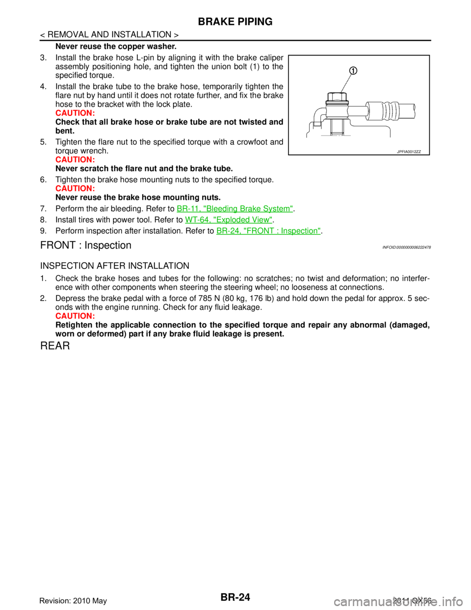
3. Install the brake hose L-pin by aligning it with the brake caliper assembly positioning hole, and tighten the union bolt (1) to the
specified torque.
4. Install the brake tube to the brake hose, temporarily tighten the flare nut by hand until it does not rotate further, and fix the brake
hose to the bracket with the lock plate.
CAUTION:
Check that all brake hose or brake tube are not twisted and
bent.
5. Tighten the flare nut to the specified torque with a crowfoot and torque wrench.
CAUTION:
Never scratch the flare nut and the brake tube.
6. Tighten the brake hose mounting nuts to the specified torque. CAUTION:
Never reuse the brake hose mounting nuts.
7. Perform the air bleeding. Refer to BR-11, "
Bleeding Brake System".
8. Install tires with power tool. Refer to WT-64, "
Exploded View".
9. Perform inspection after installation. Refer to BR-24, "
FRONT : Inspection".
FRONT : InspectionINFOID:0000000006222478
INSPECTION AFTER INSTALLATION
1. Check the brake hoses and tubes for the following: no scratches; no twist and deformation; no interfer-
ence with other components when steering the steering wheel; no looseness at connections.
2. Depress the brake pedal with a force of 785 N (80 kg, 176 lb) and hold down the pedal for approx. 5 sec- onds with the engine running. Check for any fluid leakage.
CAUTION:
Retighten the applicable connection to the specified torque and repair any abnormal (damaged,
worn or deformed) part if any brake fluid leakage is present.
REAR
JPFIA0012ZZ
Revision: 2010 May2011 QX56
Page 496 of 5598

BR-26
< REMOVAL AND INSTALLATION >
BRAKE PIPING
REAR : Removal and Installation
INFOID:0000000006222481
REMOVAL
CAUTION:
If the brake fluid adheres to the brake caliper assembly and disc rotor, quickly wipe it off.
Never spill or splash brake fluid on painted surfaces. Brake fluid may seriously damage paint. Wipe it
off immediately and wash with wate r if it gets on a painted surface.
Never depress the brake pedal. Brake fluid may spl ash while removing the brake hose or brake tube.
1. Remove tires with power tool.
2. Drain brake fluid. Refer to BR-10, "
Draining".
3. Loosen the flare nut with a flare nut wrench and separate the brake tube and the brake hose. CAUTION:
Never scratch the flare nut and the brake tube.
Never bend sharply, twist or strongly pull out the brake hose or brake tube.
Cover open end of brake hose or brake tube wh en disconnecting to prevent entrance of dirt.
4. Remove the union bolt and copper washers, and remove the brake hose from the brake caliper assembly.
5. Remove the lock plate and remove the brake hose.
INSTALLATION
CAUTION:
If the brake fluid adheres to the brake caliper assembly and disc rotor, quickly wipe it off.
Never spill or splash brake fluid on painted surfaces. Brake fluid may seriously damage paint. Wipe it
off immediately and wash with wate r if it gets on a painted surface.
Never depress the brake pedal. Brake fluid may spl ash while removing the brake hose or brake tube.
1. Assemble the union bolt and the copper washers to the brake hose. CAUTION:
Never reuse the copper washer.
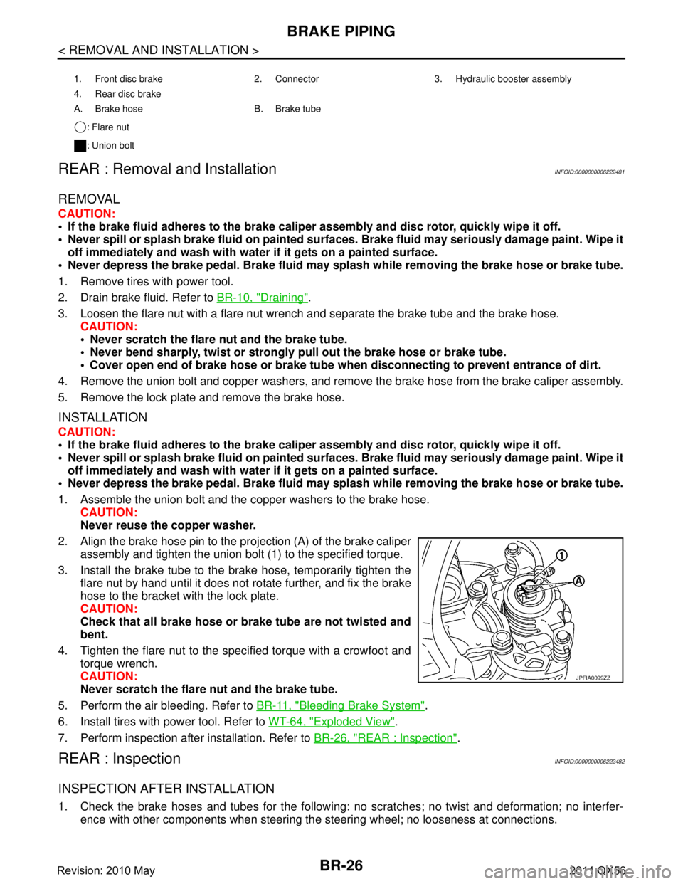
2. Align the brake hose pin to the projection (A) of the brake caliper
assembly and tighten the union bolt (1) to the specified torque.
3. Install the brake tube to the brake hose, temporarily tighten the flare nut by hand until it does not rotate further, and fix the brake
hose to the bracket with the lock plate.
CAUTION:
Check that all brake hose or brake tube are not twisted and
bent.
4. Tighten the flare nut to the specified torque with a crowfoot and torque wrench.
CAUTION:
Never scratch the flare nut and the brake tube.
5. Perform the air bleeding. Refer to BR-11, "
Bleeding Brake System".
6. Install tires with power tool. Refer to WT-64, "
Exploded View".
7. Perform inspection after installation. Refer to BR-26, "
REAR : Inspection".
REAR : InspectionINFOID:0000000006222482
INSPECTION AFTER INSTALLATION
1. Check the brake hoses and tubes for the following: no scratches; no twist and deformation; no interfer-
ence with other components when steering the steering wheel; no looseness at connections.
1. Front disc brake 2. Connector 3. Hydraulic booster assembly
4. Rear disc brake
A. Brake hose B. Brake tube
: Flare nut
: Union bolt
JPFIA0099ZZ
Revision: 2010 May2011 QX56
Page 519 of 5598

BRC-2
ADDITIONAL SERVICE WHEN REPLACING
ABS ACTUATOR AND ELECTRIC UNIT
(CONTROL UNIT) ..............................................
63
Description ........................................................... ...63
ADJUSTMENT OF STEERING ANGLE SEN-
SOR NEUTRAL POSITION ...............................
64
Description ........................................................... ...64
Work Procedure ......................................................64
CALIBRATION OF DECEL G SENSOR ...........66
Description ........................................................... ...66
Work Procedure ......................................................66
DTC/CIRCUIT DIAGNOSIS ...................... ...68
C1101, C1102, C1103, C1104 WHEEL SEN-
SOR ................................................................. ...
68
DTC Logic ............................................................ ...68
Diagnosis Procedure ..............................................68
C1105, C1106, C1107, C1108 WHEEL SEN-
SOR ....................................................................
70
DTC Logic ............................................................ ...70
Diagnosis Procedure ..............................................70
C1109 POWER AND GROUND SYSTEM .........72
Description ........................................................... ...72
DTC Logic ...............................................................72
Diagnosis Procedure ..............................................72
C1111 PUMP MOTOR .......................................75
DTC Logic ............................................................ ...75
Diagnosis Procedure ..............................................75
C1115 WHEEL SENSOR ...................................77
DTC Logic ............................................................ ...77
Diagnosis Procedure ..............................................77
C1116 STOP LAMP SWITCH ............................79
DTC Logic ............................................................ ...79
Diagnosis Procedure ..............................................79
Component Inspection (Stop lamp Switch) ............85
Component Inspection (Stop Lamp Relay) .............86
C1118 TRANSFER CONTROL UNIT ................87
DTC Logic ............................................................ ...87
Diagnosis Procedure ..............................................87
C1120, C1122, C1124, C1126 ABS IN VALVE
SYSTEM .......................................................... ...
88
DTC Logic ............................................................ ...88
Diagnosis Procedure ..............................................88
C1121, C1123, C1125, C1127 ABS OUT
VALVE SYSTEM ................................................
90
DTC Logic ............................................................ ...90
Diagnosis Procedure ..............................................90
C1130 ENGINE SIGNAL ...................................92
DTC Logic ............................................................ ...92
Diagnosis Procedure ............................................ ...92
C1140 ACTUATOR RELAY SYSTEM ..............93
DTC Logic ............................................................ ...93
Diagnosis Procedure ...............................................93
C1142 PRESS SENSOR ...................................95
DTC Logic ............................................................ ...95
Diagnosis Procedure ...............................................95
C1143 STEERING ANGLE SENSOR ...............97
DTC Logic ............................................................ ...97
Diagnosis Procedure ...............................................97
C1144 INCOMPLETE STEERING ANGLE
SENSOR ADJUSTMENT ..................................
99
DTC Logic ............................................................ ...99
Diagnosis Procedure ...............................................99
C1145, C1146 YAW RATE/SIDE/DECEL G
SENSOR ...........................................................
100
DTC Logic ............................................................ .100
Diagnosis Procedure .............................................100
C1155 BRAKE FLUID LEVEL SWITCH ..........103
DTC Logic ............................................................ .103
Diagnosis Procedure .............................................103
Component Inspection ..........................................104
C1160 DECEL G SEN SET ..............................105
DTC Logic ............................................................ .105
Diagnosis Procedure .............................................105
C1164, C1165 CV SYSTEM .............................106
DTC Logic ............................................................ .106
Diagnosis Procedure .............................................106
C1166, C1167 SV SYSTEM .............................108
DTC Logic ............................................................ .108
Diagnosis Procedure .............................................108
C1170 VARIANT CODING ...............................110
DTC Logic ............................................................ .110
Diagnosis Procedure .............................................110
C118E ACCUMULATOR ..................................111
DTC Logic ............................................................ .111
Diagnosis Procedure .............................................111
U1000 CAN COMM CIRCUIT ...........................112
Description ........................................................... .112
DTC Logic .............................................................112
Diagnosis Procedure .............................................112
POWER SUPPLY AND GROUND CIRCUIT ....113
Description ........................................................... .113
Diagnosis Procedure .............................................113
PARKING BRAKE SWITCH .............................117
Component Function Check ................................ .117
Diagnosis Procedure .............................................117
Component Inspection ..........................................118
Revision: 2010 May2011 QX56
Page 532 of 5598
![INFINITI QX56 2011 Factory Service Manual
COMPONENT PARTSBRC-15
< SYSTEM DESCRIPTION > [WITH VDC]
C
D
E
G H
I
J
K L
M A
B
BRC
N
O P
Downsize and weight reduction is aimed. IC for detection portion and magnet for sensor rotor are adopted.
INFINITI QX56 2011 Factory Service Manual
COMPONENT PARTSBRC-15
< SYSTEM DESCRIPTION > [WITH VDC]
C
D
E
G H
I
J
K L
M A
B
BRC
N
O P
Downsize and weight reduction is aimed. IC for detection portion and magnet for sensor rotor are adopted.
](/manual-img/42/57033/w960_57033-531.png)
COMPONENT PARTSBRC-15
< SYSTEM DESCRIPTION > [WITH VDC]
C
D
E
G H
I
J
K L
M A
B
BRC
N
O P
Downsize and weight reduction is aimed. IC for detection portion and magnet for sensor rotor are adopted.
Power supply is supplied to detection portion so that magnetic field
line is read. Magnetic field that is detected is converted to current
signal.
When sensor rotor rotates, magnetic field changes. Magnetic field
change is converted to current signals (rectangular wave) and is
transmitted to ABS actuator and electric unit (control unit). Change
of magnetic field is pr oportional to wheel speed.
Stop Lamp SwitchINFOID:0000000006222563
Detects the operation status of brake pedal and transmits converted electric signal to ABS actuator and elec-
tric unit (control unit).
Steering Angle SensorINFOID:0000000006222564
Detects the following information and transmits steering angle signal to ABS actuator and electric unit (control
unit) via CAN communication.
Steering wheel rotation amount
Steering wheel rotation angular velocity
Steering wheel rotation direction
Yaw Rate/Side/Decel G sensorINFOID:0000000006222565
Calculates the following information that affects the v ehicle and transmits a signal to ABS actuator and electric
unit (control unit) via communication lines.
Vehicle rotation angular velocity (yaw rate signal)
Vehicle lateral acceleration (side G signal) / longitudinal acceleration (decel G signal)
Brake Fluid Level SwitchINFOID:0000000006222566
Detects the brake fluid level in reservoir tank and trans mits converted electric signal from ABS actuator and
electric unit (control unit), when brake fluid level is the specified level or less.
Parking Brake SwitchINFOID:0000000006222567
Detects the operation status of parking brake switch and transmits converted electric signal from combination
meter to ABS actuator and electric unit (control unit).
VDC OFF SwitchINFOID:0000000006222568
VDC OFF switch is integrated in SNOW MODE / TOW MODE / VDC OFF switch assembly (2WD models) or
4WD switch assembly (4WD models).
The operation of the VDC OFF switch enables the arbi trary switching of the VDC function between stop sta-
tus and standby status. The status of the function is indicated by the VDC OFF indicator lamp. (ON: Non-
operational status, OFF: Standby status)
- VDC function NOTE:
Brake limited slip differentia l (BLSD) control operates.
- TCS function
VDC OFF indicator lamp turns OFF (standby status) when the engine is started again after it is stopped once while VDC OFF indicator lamp is ON (non-operational status).
JPFIC0131GB
Revision: 2010 May2011 QX56
Page 534 of 5598
![INFINITI QX56 2011 Factory Service Manual
SYSTEMBRC-17
< SYSTEM DESCRIPTION > [WITH VDC]
C
D
E
G H
I
J
K L
M A
B
BRC
N
O P*1: Communication line between yaw rate/side/decal G s ensor and ABS actuator and electric unit (control unit)
*2: Mode INFINITI QX56 2011 Factory Service Manual
SYSTEMBRC-17
< SYSTEM DESCRIPTION > [WITH VDC]
C
D
E
G H
I
J
K L
M A
B
BRC
N
O P*1: Communication line between yaw rate/side/decal G s ensor and ABS actuator and electric unit (control unit)
*2: Mode](/manual-img/42/57033/w960_57033-533.png)
SYSTEMBRC-17
< SYSTEM DESCRIPTION > [WITH VDC]
C
D
E
G H
I
J
K L
M A
B
BRC
N
O P*1: Communication line between yaw rate/side/decal G s ensor and ABS actuator and electric unit (control unit)
*2: Models with 4WD system
VALVE OPERATION
Each valve is operated and fluid pressure of brake caliper is controlled.
When Ordinary Brake is Applied
NOTE:
Control pressure sensor is applied to model s with Advanced Driver Assistance System.
TCMMainly transmits the following signals to ABS actuator and electric unit (control unit) via CAN
communication.
Shift position signal
Current gear position signal
Transfer control unit
*2Mainly transmits the following signals to ABS actuator and electric unit (control unit) via CAN
communication.
Current 4WD mode signal
Steering angle sensor Mainly transmits the following signals to ABS actuator and electric unit (control unit) via CAN
communication.
Steering angle sensor signal
Combination meter Mainly receives the following signals from ABS actuator and electric unit (control unit) via CAN
communication.
ABS warning lamp signal
Brake warning lamp signal
VDC warning lamp signal
VDC OFF indicator lamp
Component Signal description
Name Not activated When depressing brake pedal
Cut valve 1 Power supply is not supplied (open) Power supply is not supplied (open)
Cut valve 2 Power supply is not supplied (open) Power supply is not supplied (open)
Suction valve 1 Power supply is not supplied (close) Power supply is not supplied (close)
Suction valve 2 Power supply is not supplied (close) Power supply is not supplied (close)
JPFIC0150GB
Revision: 2010 May2011 QX56
Page 1788 of 5598

DLK-252
< REMOVAL AND INSTALLATION >
CAB MOUNTING INSULATOR
Drain brake fluid from brake line. Refer to BR-10, "Draining".
Release fuel pressure. Refer to EC-153, "
Work Procedure".
Disconnect both battery cables. Refer to PG-164, "
Removal and Installation".
Drain engine coolant from radiator. Refer to CO-8, "
Draining".
Discharge refrigerant from A/C circuit. Refer to HA-20, "
Recycle Refrigerant".
Drain power steering fluid from reservoir tank.
4. Remove parts relating to connection of body assembly and frame assembly. Tire and wheel: Refer to WT-64, "
Removal and Installation" (with TPMS).
Front fender protector (LH and RH): Refer to EXT-23, "
FENDER PROTECTOR : Removal and Installa-
tion".
Front bumper: Refer to EXT-13, "
Removal and Installation".
Radiator core support upper: Refer to DLK-220, "
Removal and Installation".
Fan shroud: Refer to CO-16, "
Removal and Installation".
Battery and battery case: Refer to PG-164, "
Removal and Installation".
Air cleaner case (upper and lower): Refer to EM-27, "
Removal and Installation".
Engine cover: Refer to EM-25, "
Removal and Installation".
Rear wheel house protector (LH and RH): EXT-24, "
REAR WHEEL HOUSE PROTECTOR : Removal
and Installation".
Rear bumper: Refer to EXT-17, "
Removal and Installation".
Fuel filler tube: Remove to FL-8, "
Exploded View".
Spare tire
Towing hook bracket.
5. Separate parts relating to connection of body assembly and frame assembly. Vehicle front
Disconnect ICC sensor connector. (models with ICC) Refer to CCS-176, "
Removal and Installation".
Remove radiator upper hose and radiator lower hose from radiator assembly. Refer to CO-13,
"Exploded View".
Remove A/T fluid cooler hose B and A/T fluid cooler hose E from A/T fluid cooler tubes. Refer to TM-
202, "Exploded View".
Remove power steering return hose from oil cooler, and then power steering return hose clamp bolt from frame assembly. Refer to ST-54, "
Exploded View".
Remove power steering suction hose from reservoir tank. Refer to ST-54, "
Exploded View".
CAUTION:
Never spill power steering fluid in engine room.
Remove A/C low-presser flexible hose from A/C low-presser pipe. Refer to HA-35, "
LOW-PRESSURE
FLEXIBLE HOSE : Removal and Installation".
Remove A/C hi-presser flexible hose from condenser. Refer to HA-34, "
HIGH-PRESSURE FLEXIBLE
HOSE : Removal and Installation".
Remove all engine Control Harness connectors, har ness clips and others that are connected to the
body assembly side of the engine room. (engine room LH and RH side). Refer to PG-148, "
Engine Con-
trol Harness".
NOTE:
Separate harness connectors from ECM (engine control module). Refer to EC-10, "
General Precau-
tions".
CAUTION:
When pulling out harnesses, never damage harnesses or connectors.
After temporarily securing connectors, cover th em with vinyl or similar material to protect
against adhesion of foreign materials.
Disconnect engine room harness connectors and remo ve harness clips from engine assembly (engine
RH side). Refer to PG-146, "
Engine Room Harness".
Remove heater hoses from front water outlet tube (engine room RH side). Refer to HA-33, "
Exploded
View".
Disconnect front wheel sensor connectors (LH and RH). Refer to BRC-134, "
FRONT WHEEL SENSOR
: Exploded View".
Disconnect fuel feed tube and EVAP hos e (front wheel well LH side).
Remove steering lower shaft from steering gear side assembly. Refer to ST-37, "
Removal and Installa-
tion"
CAUTION:
Spiral cable may be cut if steering wheel turns while separating steering column assembly and
steering gear assembly.
Revision: 2010 May2011 QX56
Page 1804 of 5598

DLN-2
Work Procedure ......................................................47
CONFIGURATION (TRANSFER CONTROL
UNIT) ..................................................................
48
Description ........................................................... ...48
Work Procedure ......................................................48
DTC/CIRCUIT DIAGNOSIS ...................... ...51
P1802, P1803, P1804, P1809 TRANSFER
CONTROL UNIT ............................................. ...
51
DTC Logic ............................................................ ...51
Diagnosis Procedure ..............................................51
P1807 OUT PUT SHAFT SPEED SENSOR ......52
DTC Logic ............................................................ ...52
Diagnosis Procedure ..............................................52
P1808 WHEEL SPEED SENSOR ......................53
DTC Logic ............................................................ ...53
Diagnosis Procedure ..............................................53
P180C SENSOR POWER SUPPLY (5V) ..........54
Description ........................................................... ...54
DTC Logic ...............................................................54
Diagnosis Procedure ..............................................54
P180D TRANSFER ROTARY POSITION
SENSOR ............................................................
57
DTC Logic ............................................................ ...57
Diagnosis Procedure ..............................................57
P180E SENSOR POWER SUPPLY (8V) ...........59
Description ........................................................... ...59
DTC Logic ...............................................................59
Diagnosis Procedure ..............................................59
P180F TRANSFER INTERNAL SPEED SEN-
SOR ....................................................................
61
DTC Logic ............................................................ ...61
Diagnosis Procedure ..............................................61
P1811 POWER SUPPLY CIRCUIT FOR
TRANSFER CONTROL UNIT ............................
64
Description ........................................................... ...64
DTC Logic ...............................................................64
Diagnosis Procedure ..............................................64
P1813 4WD MODE SWITCH .............................67
DTC Logic ............................................................ ...67
Diagnosis Procedure ..............................................67
Component Inspection ............................................68
P1816 PARKING/NEUTRAL POSITION
SWITCH .............................................................
69
DTC Logic ............................................................ ...69
Diagnosis Procedure ..............................................69
P1817 TRANSFER MOTOR ..............................70
DTC Logic ............................................................ ...70
Diagnosis Procedure ..............................................70
Component Inspection ......................................... ...71
P181A TRANSFER MOTOR TEMPERATURE
SENSOR ............................................................
72
DTC Logic ............................................................ ...72
Diagnosis Procedure ...............................................72
Component Inspection ............................................73
P181B INCOMPLETE SELFSHUT ....................74
DTC Logic ............................................................ ...74
Diagnosis Procedure ...............................................74
P181C TRANSFER MOTOR POWER SUP-
PLY ....................................................................
76
Description ........................................................... ...76
DTC Logic ...............................................................76
Diagnosis Procedure ...............................................76
P181E STEERING ANGLE SENSOR ...............77
DTC Logic ............................................................ ...77
Diagnosis Procedure ...............................................77
P181F INCOMPLETE CALIBRATION ..............78
DTC Logic ............................................................ ...78
Diagnosis Procedure ...............................................78
P1820 ENGINE SPEED SIGNAL ......................79
DTC Logic ............................................................ ...79
Diagnosis Procedure ...............................................79
P1826 TRANSFER FLUID TEMPERATURE ....80
DTC Logic ............................................................ ...80
Diagnosis Procedure ...............................................80
Component Inspection ............................................81
P1829 ACCELERATOR PEDAL POSITION
SENSOR ............................................................
82
DTC Logic ............................................................ ...82
Diagnosis Procedure ...............................................82
P182A TRANSFER HI-LO POSITION SEN-
SOR ...................................................................
83
DTC Logic ............................................................ ...83
Diagnosis Procedure ...............................................83
P182B TRANSFER LOCK POSITION SEN-
SOR ...................................................................
85
DTC Logic ............................................................ ...85
Diagnosis Procedure ...............................................85
P1830 ABS OPERATION SIGNAL ...................88
DTC Logic ............................................................ ...88
Diagnosis Procedure ...............................................88
P1831 VDC OPERATION SIGNAL ...................89
DTC Logic ............................................................ ...89
Diagnosis Procedure ...............................................89
P1832 TCS OPERATION SIGNAL ....................90
DTC Logic ............................................................ ...90
Diagnosis Procedure ...............................................90
Revision: 2010 May2011 QX56
Page 2595 of 5598

ROCKER COVEREM-33
< REMOVAL AND INSTALLATION >
C
DE
F
G H
I
J
K L
M A
EM
NP
O
ROCKER COVER
Exploded ViewINFOID:0000000006289545
Removal and InstallationINFOID:0000000006289546
REMOVAL
1. Remove engine cover and bracket (rear). Refer to
EM-25, "Exploded View".
2. Disconnect PCV hose from rocker cover.
3. Remove air cleaner case (upper) and air duct. Refer to EM-27, "
Exploded View".
4. Move the following parts to the position without the hindrance for work. Oil level gauge guide. Refer to EM-57, "
Exploded View".
Power steering fluid reservoir tank bracket. Refer to ST-54, "
Exploded View".
EVAP canister purge control solenoid valve. EM-30, "
Exploded View".
Fuel feed hose. Refer to EM-43, "
Exploded View".
5. Remove VVEL actuator motor assembly. Refer to EM-36, "
Exploded View".
6. Remove ignition coil. Refer to EM-29, "
Exploded View".
CAUTION:
Never impact it.
7. Remove rocker cover.
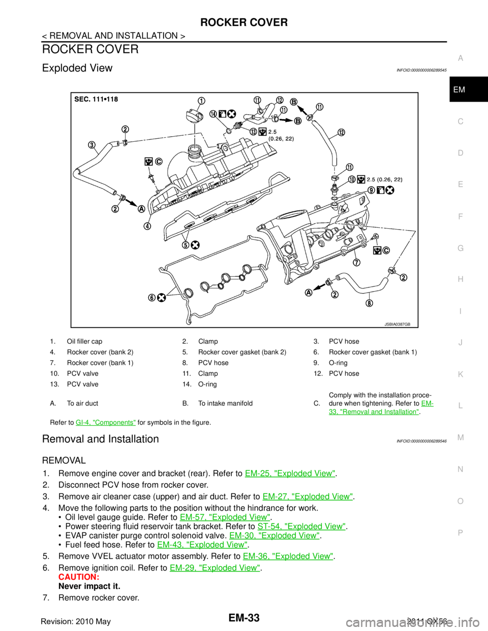
1. Oil filler cap 2. Clamp 3. PCV hose
4. Rocker cover (bank 2) 5. Rocker cover gasket (bank 2) 6. Rocker cover gasket (bank 1)
7. Rocker cover (bank 1) 8. PCV hose 9. O-ring
10. PCV valve 11. Clamp 12. PCV hose
13. PCV valve 14. O-ring
A. To air duct B. To intake manifold C. Comply with the installation proce-
dure when tightening. Refer to
EM-
33, "Removal and Installation".
Refer to GI-4, "
Components" for symbols in the figure.
JSBIA0387GB
Revision: 2010 May2011 QX56