2011 INFINITI QX56 sensor
[x] Cancel search: sensorPage 1495 of 5598
PRECAUTIONSDEF-3
< PRECAUTION >
C
DE
F
G H
I
J
K
M A
B
DEF
N
O P
PRECAUTION
PRECAUTIONS
Precaution for Supplemental Restraint System (SRS) "AIR BAG" and "SEAT BELT
PRE-TENSIONER"
INFOID:0000000006349779
The Supplemental Restraint System such as “A IR BAG” and “SEAT BELT PRE-TENSIONER”, used along
with a front seat belt, helps to reduce the risk or severi ty of injury to the driver and front passenger for certain
types of collision. This system includes seat belt switch inputs and dual stage front air bag modules. The SRS
system uses the seat belt switches to determine the front air bag deployment, and may only deploy one front
air bag, depending on the severity of a collision and whether the front occupants are belted or unbelted.
Information necessary to service the system safely is included in the “SRS AIR BAG” and “SEAT BELT” of this
Service Manual.
WARNING:
• To avoid rendering the SRS inoper ative, which could increase the risk of personal injury or death in
the event of a collision that would result in air ba g inflation, all maintenance must be performed by
an authorized NISSAN/INFINITI dealer.
Improper maintenance, including in correct removal and installation of the SRS, can lead to personal
injury caused by unintentional act ivation of the system. For removal of Spiral Cable and Air Bag
Module, see the “SRS AIR BAG”.
Do not use electrical test equipm ent on any circuit related to the SRS unless instructed to in this
Service Manual. SRS wiring harnesses can be identi fied by yellow and/or orange harnesses or har-
ness connectors.
PRECAUTIONS WHEN USING POWER TOOLS (AIR OR ELECTRIC) AND HAMMERS
WARNING:
When working near the Air Bag Diagnosis Sensor Unit or other Air Bag System sensors with the
ignition ON or engine running, DO NOT use air or electric power tools or strike near the sensor(s)
with a hammer. Heavy vibration could activate the sensor(s) and deploy the air bag(s), possibly
causing serious injury.
When using air or electric power tools or hammers , always switch the ignition OFF, disconnect the
battery, and wait at least 3 minutes before performing any service.
Precaution Necessary for Steering Wh eel Rotation after Battery Disconnect
INFOID:0000000006299422
NOTE:
Before removing and installing any control units, first tu rn the push-button ignition switch to the LOCK posi-
tion, then disconnect both battery cables.
After finishing work, confirm that all control unit connectors are connected properly, then re-connect both
battery cables.
Always use CONSULT-III to perform self-diagnosis as a part of each function inspection after finishing work.
If a DTC is detected, perform trouble diagnos is according to self-diagnosis results.
This vehicle is equipped with a push-button ignition switch and a steering lock unit.
If the battery is disconnect ed or discharged, the steering wheel will lock and cannot be turned.
If turning the steering wheel is required with the battery disconnected or discharged, follow the procedure
below before starting the repair operation.
OPERATION PROCEDURE
1. Connect both battery cables. NOTE:
Supply power using jumper cables if battery is discharged.
2. Turn the push-button ignition switch to ACC position. (At this time, the steering lock will be released.)
3. Disconnect both battery cables. The steering lock wil l remain released with both battery cables discon-
nected and the steering wheel can be turned.
4. Perform the necessary repair operation.
Revision: 2010 May2011 QX56
Page 1538 of 5598

DLK-2
DOOR LOCK .............................................................39
DOOR LOCK : CONSULT-III Function (BCM -
DOOR LOCK) .........................................................
39
INTELLIGENT KEY ................................................ ...40
INTELLIGENT KEY : CONSULT-III Function
(BCM - INTELLIGENT KEY) ...................................
41
TRUNK ................................................................... ...44
TRUNK : CONSULT-III Function (BCM - TRUNK) ...44
DIAGNOSIS SYSTEM (AUTOMATIC BACK
DOOR CONTROL UNIT) ...................................
45
CONSULT-III Function (AUTOMATIC BACK
DOOR CONTROL UNIT) ..................................... ...
45
ECU DIAGNOSIS INFORMATION ..............46
BCM ................................................................ ...46
List of ECU Reference ......................................... ...46
AUTOMATIC BACK DOOR CONTROL MOD-
ULE ....................................................................
47
Reference Value .................................................. ...47
Fail Safe .................................................................49
DTC Inspection Priority Chart ..............................49
DTC Index ..............................................................50
WIRING DIAGRAM .....................................51
DOOR & LOCK SYSTEM ............................... ...51
Wiring Diagram - DOOR & LOCK SYSTEM - ...... ...51
AUTOMATIC BACK DOOR SYSTEM ...............66
Wiring Diagram - AUTOMATIC BACK DOOR
SYSTEM - ............................................ ...................
66
INTEGRATED HOMELINK TRANSMITTER
SYSTEM ............ .............................................. ...
75
Wiring Diagram - INTEGRATED HOMELINK
TRANSMITTER SYSTEM - ....................................
75
BASIC INSPECTION ...... .............................77
DIAGNOSIS AND REPAIR WORK FLOW ..... ...77
Work Flow ............................................................ ...77
INSPECTION AND ADJUSTMENT ...................80
ADDITIONAL SERVICE WHEN REMOVING BAT-
TERY NEGATIVE TERMINAL ............................... ...
80
ADDITIONAL SERVICE WHEN REMOVING
BATTERY NEGATIVE TERMINAL : Description ....
80
ADDITIONAL SERVICE WHEN REMOVING
BATTERY NEGATIVE TERMINAL : Work Proce-
dure ........................................................................
80
ADDITIONAL SERVICE WHEN REPLACING
CONTROL UNIT (BCM) ......................................... ...
80
ADDITIONAL SERVICE WHEN REPLACING
CONTROL UNIT (BCM) : Description ....................
80
ADDITIONAL SERVICE WHEN REPLACING
CONTROL UNIT (BCM) : Work Procedure .......... ...
80
ADDITIONAL SERVICE WHEN REPLACING (AU-
TOMATIC BACK DOOR CONTROL MODULE) .......
80
ADDITIONAL SERVICE WHEN REPLACING
(AUTOMATIC BACK DOOR CONTROL MOD-
ULE) : Description ................................................ ...
80
ADDITIONAL SERVICE WHEN REPLACING
(AUTOMATIC BACK DOOR CONTROL MOD-
ULE) : Work Procedure ........................................ ...
80
DTC/CIRCUIT DIAGNOSIS ........................82
U1000 CAN COMM CIRCUIT ......................... ...82
Description ........................................................... ...82
DTC Logic ...............................................................82
Diagnosis Procedure ...............................................82
U1010 CONTROL UNIT (CAN) .........................83
DTC Logic ............................................................ ...83
Diagnosis Procedure ...............................................83
B2401 IGNITION POWER SUPPLY CIRCUIT ...84
DTC Logic ............................................................ ...84
Diagnosis Procedure ...............................................84
B2403 ENCODER ..............................................85
DTC Logic ............................................................ ...85
Diagnosis Procedure ...............................................85
B2409 HALF LATCH SWITCH ..........................86
DTC Logic ............................................................ ...86
Diagnosis Procedure ...............................................86
Component Inspection ............................................87
B2416 TOUCH SENSOR RH ............................88
DTC Logic ............................................................ ...88
Diagnosis Procedure ...............................................88
Component Inspection ............................................89
B2417 TOUCH SENSOR LH .............................90
DTC Logic ............................................................ ...90
Diagnosis Procedure ...............................................90
Component Inspection ............................................91
B2419 OPEN SWITCH ......................................92
DTC Logic ............................................................ ...92
Diagnosis Procedure ...............................................92
Component Inspection ............................................93
B2420 CLOSE SWITCH ....................................95
DTC Logic ............................................................ ...95
Diagnosis Procedure ...............................................95
Component Inspection ............................................96
B2421 CLUTCH OPERATION TIME .................97
DTC Logic ............................................................ ...97
Diagnosis Procedure ...............................................97
B2422 BACK DOOR STATE .............................98
DTC Logic ............................................................ ...98
Revision: 2010 May2011 QX56
Page 1539 of 5598
DLK-3
C
DE
F
G H
I
J
L
M A
B
DLK
N
O P
Diagnosis Procedure ...........................................
....
98
B2423 AUTOMATIC BACK DOOR MOTOR
OPERATION TIME .............................................
99
DTC Logic ........................................................... ....99
Diagnosis Procedure ...............................................99
B2424 CLOSURE CONDITION ........................100
DTC Logic ........................................................... ..100
Diagnosis Procedure .............................................100
Component Inspection ..........................................101
B2425 AUTOMATIC BACK DOOR CONTROL
UNIT ..................................................................
103
DTC Logic ........................................................... ..103
Diagnosis Procedure .............................................103
B2621 INSIDE ANTENNA ................................104
DTC Logic ........................................................... ..104
Diagnosis Procedure .............................................104
B2622 INSIDE ANTENNA ................................106
DTC Logic ........................................................... ..106
Diagnosis Procedure .............................................106
B2623 INSIDE ANTENNA ................................108
DTC Logic ........................................................... ..108
Diagnosis Procedure .............................................108
B2626 OUTSIDE ANTENNA ............................110
DTC Logic ........................................................... ..110
Diagnosis Procedure .............................................110
B2627 OUTSIDE ANTENNA ............................112
DTC Logic ........................................................... ..112
Diagnosis Procedure .............................................112
B2628 OUTSIDE ANTENNA ............................114
DTC Logic ........................................................... ..114
Diagnosis Procedure .............................................114
POWER SUPPLY AND GROUND CIRCUIT ....116
AUTOMATIC BACK DOOR CONTROL UNIT ...... ..116
AUTOMATIC BACK DOOR CONTROL UNIT : Di-
agnosis Procedure ................................................
116
DOOR SWITCH ................................................117
Component Function Check .............................. ..117
Diagnosis Procedure .............................................117
Component Inspection ..........................................119
BACK DOOR SWITCH .....................................120
Component Function Check .............................. ..120
Diagnosis Procedure .............................................120
Component Inspection ..........................................121
DOOR LOCK AND UNLOCK SWITCH ............122
DRIVER SIDE ........................................................ ..122
DRIVER SIDE : Component Function Check ......122
DRIVER SIDE : Diagnosis Procedure ...................122
PASSENGER SIDE ..................................................122
PASSENGER SIDE :
Component Function Check .............................. ..
122
PASSENGER SIDE : Diagnosis Procedure ..........122
DOOR LOCK ACTUATOR ..............................123
DRIVER SIDE ......................................................... ..123
DRIVER SIDE : Component Function Check ......123
DRIVER SIDE : Diagnosis Procedure ...................123
PASSENGER SIDE ..................................................124
PASSENGER SIDE :
Component Function Check .............................. ..
124
PASSENGER SIDE : Diagnosis Procedure ..........124
REAR LH ................................................................ ..125
REAR LH : Component Function Check ..............125
REAR LH : Diagnosis Procedure ...........................125
REAR RH ............................................................... ..126
REAR RH : Component Function Check .............126
REAR RH : Diagnosis Procedure ..........................126
FUEL LID LOCK ACTUATOR ........................128
Component Function Check ................................128
Diagnosis Procedure .............................................128
UNLOCK SENSOR .........................................130
Component Function Check ................................130
Diagnosis Procedure .............................................130
Component Inspection ...........................................131
DOOR KEY CYLINDER SWITCH ...................132
Component Function Check ..................................132
Diagnosis Procedure .............................................132
Component Inspection ...........................................133
REMOTE KEYLESS ENTRY RECEIVER .......134
Component Function Check ................................134
Diagnosis Procedure .............................................134
DOOR REQUEST SWITCH ............................137
Component Function Check ................................137
Diagnosis Procedure .............................................137
Component Inspection ...........................................138
BACK DOOR REQUEST SWITCH .................139
Component Function Check ................................139
Diagnosis Procedure .............................................139
Component Inspection ...........................................140
BACK DOOR OPENER SWITCH ...................141
Component Function Check ................................141
Diagnosis Procedure .............................................141
Component Inspection ...........................................142
INTELLIGENT KEY WARNING BUZZER .......143
Component Function Check ................................143
Diagnosis Procedure .............................................143
Component Inspection ...........................................144
INTELLIGENT KEY .........................................145
Revision: 2010 May2011 QX56
Page 1540 of 5598

DLK-4
Component Function Check ................................145
Diagnosis Procedure .............................................145
COMBINATION METER BUZZER ..................146
Component Function Check .............................. ..146
Diagnosis Procedure .............................................146
INFORMATION DISPLAY ...............................147
Component Function Check .............................. ..147
Diagnosis Procedure .............................................147
KEY WARNING LAMP ....................................148
Component Function Check .............................. ..148
Diagnosis Procedure .............................................148
HAZARD FUNCTION .......................................149
Component Function Check .............................. ..149
Diagnosis Procedure .............................................149
AUTOMATIC BACK DOOR CLOSE SWITCH .150
Component Function Check .............................. ..150
Diagnosis Procedure .............................................150
Component Inspection ...........................................151
AUTOMATIC BACK DOOR MAIN SWITCH ...152
Component Function Check .............................. ..152
Diagnosis Procedure .............................................152
Component Inspection ...........................................153
AUTOMATIC BACK DOOR SWITCH .............154
Component Function Check .............................. ..154
Diagnosis Procedure .............................................154
Component Inspection ...........................................155
HALF LATCH SWITCH ...................................156
Component Function Check ................................ ..156
Diagnosis Procedure .............................................156
Component Inspection ...........................................157
TOUCH SENSOR ............................................158
RH ........................................................................... ..158
RH : Component Function Check ........................158
RH : Diagnosis Procedure .....................................158
RH : Component Inspection ..................................159
LH ........................................................................... ..159
LH : Component Function Check .........................159
LH : Diagnosis Procedure ......................................159
LH : Component Inspection ...................................160
BACK DOOR CLOSURE MOTOR ..................162
Diagnosis Procedure ........................................... ..162
AUTOMATIC BACK DOOR WARNING BUZZ-
ER ....................................................................
163
Diagnosis Procedure ........................................... ..163
Component Inspection ...........................................163
GROUND CIRCUIT ......................................... .165
Component Function Check .............................. ..165
Diagnosis Procedure .............................................165
INTEGRATED HOMELINK TRANSMITTER ....166
Component Function Check ............................... .166
Diagnosis Procedure .............................................166
SYMPTOM DIAGNOSIS ...........................168
DOOR DOES NOT LOCK/UNLOCK WITH
DOOR LOCK AND UNLOCK SWITCH .......... ..
168
ALL DOOR ............................................................. .168
ALL DOOR : Description .......................................168
ALL DOOR : Diagnosis Procedure .......................168
DRIVER SIDE ......................................................... .168
DRIVER SIDE : Description ..................................168
DRIVER SIDE : Diagnosis Procedure ...................168
PASSENGER SIDE .................................................168
PASSENGER SIDE : Descripti on .........................169
PASSENGER SIDE : Diagnos is Procedure ..........169
REAR LH ................................................................ .169
REAR LH : Description .........................................169
REAR LH : Diagnosis Procedure ..........................169
REAR RH ................................................................ .169
REAR RH : Description .........................................169
REAR RH : Diagnosis Procedure .........................169
DOOR DOES NOT LOCK/UNLOCK WITH
DOOR KEY CYLINDER OPERATION .............
171
Diagnosis Procedure ............................................ .171
DOOR DOES NOT LOCK/UNLOCK WITH
DOOR REQUEST SWITCH ..............................
172
ALL DOOR REQUEST SWITCHES ....................... .172
ALL DOOR REQUEST SWITCHES : Description .172
ALL DOOR REQUEST SWITCHES : Diagnosis
Procedure .............................................................
172
DRIVER SIDE DOOR REQUEST SWITCH ............ .173
DRIVER SIDE DOOR REQUEST SWITCH : De-
scription .................................................................
173
DRIVER SIDE DOOR REQUEST SWITCH : Diag-
nosis Procedure ....................................................
173
PASSENGER SIDE DOOR REQUEST SWITCH ... .173
PASSENGER SIDE DOOR REQUEST SWITCH :
Description ............................................................
173
PASSENGER SIDE DOOR REQUEST SWITCH :
Diagnosis Procedure .............................................
173
BACK DOOR REQUEST SWITCH ........................ .173
BACK DOOR REQUEST SWITCH : Description ..173
BACK DOOR REQUEST SWITCH : Diagnosis
Procedure .............................................................
173
DOOR DOES NOT LOCK/UNLOCK WITH IN-
TELLIGENT KEY ..............................................
175
Diagnosis Procedure ............................................ .175
Revision: 2010 May2011 QX56
Page 1543 of 5598
DLK-7
C
DE
F
G H
I
J
L
M A
B
DLK
N
O P
Exploded View ....................................................
..
243
DOOR LOCK ......................................................... ..243
DOOR LOCK : Removal and Installation ..............243
INSIDE HANDLE ................................................... ..243
INSIDE HANDLE : Removal and Installation ........244
OUTSIDE HANDLE ............................................... ..244
OUTSIDE HANDLE : Removal and Installation ....244
BACK DOOR LOCK .........................................246
Exploded View .................................................... ..246
DOOR LOCK ......................................................... ..246
DOOR LOCK : Removal and Installation ..............246
TOUCH SENSOR .................................................. ..246
TOUCH SENSOR : Removal and Installation .......246
BACK DOOR SUPPORT ROD .............................. ..247
BACK DOOR SUPPORT ROD : Removal and In-
stallation ................................................................
247
EMERGENCY LEVER ........................................... ..247
EMERGENCY LEVER : Unlock procedures .........247
FUEL FILLER LID OPENER ............................248
Exploded View .................................................... ..248
Removal and Installation .......................................248
KEY CYLINDER ...............................................250
GLOVE BOX LID KEY CYLINDER ....................... ..250
GLOVE BOX LID KEY CYLINDER : Removal and
Installation .............................................................
250
CAB MOUNTING INSULATOR ........................251
Exploded View .................................................... ..251
Removal and Installation .......................................251
DOOR SWITCH ................................................254
Removal and Installation ..................................... ..254
DOOR REQUEST SWITCH ..............................255
DRIVER SIDE ........................................................ ..255
DRIVER SIDE : Removal and Installation .............255
PASSENGER SIDE .................................................255
PASSENGER SIDE : Removal and Installation .. ..255
BACK DOOR ......................................................... ..255
BACK DOOR : Removal and Installation ..............255
INSIDE KEY ANTENNA ..................................256
INSTRUMENT CENTER ........................................ ..256
INSTRUMENT CENTER : Removal and Installa-
tion .........................................................................
256
CONSOLE .............................................................. ..256
CONSOLE : Removal and Installation ...................256
LUGGAGE ROOM ................................................. ..256
LUGGAGE ROOM : Removal and Installation ......256
OUTSIDE KEY ANTENNA ..............................257
DRIVER SIDE ......................................................... ..257
DRIVER SIDE : Removal and Installation .............257
PASSENGER SIDE ..................................................257
PASSENGER SIDE : Removal and Installation .. ..257
BACK DOOR ......................................................... ..257
BACK DOOR : Removal and Installation ...............257
INTELLIGENT KEY WARNING BUZZER .......258
Removal and Installation .......................................258
REMOTE KEYLESS ENTRY RECEIVER .......259
Removal and Installation .......................................259
INTELLIGENT KEY BATTERY .......................260
Removal and Installation .......................................260
BACK DOOR CONTROL UNIT ......................261
Removal and Installation ..................................... ..261
AUTOMATIC BACK DOOR CONTROL MOD-
ULE ..................................................................
262
Removal and Installation .......................................262
AUTOMATIC BACK DOOR WARNING BUZZ-
ER ....................................................................
263
Removal and Installation .......................................263
AUTOMATIC BACK DOOR MAIN SWITCH ...264
Removal and Installation .......................................264
AUTOMATIC BACK DOOR CLOSE SWITCH .265
Removal and Installation ..................................... ..265
AUTOMATIC BACK DOOR SWITCH .............266
Removal and Installation .......................................266
Revision: 2010 May2011 QX56
Page 1544 of 5598
DLK-8
< PRECAUTION >
PRECAUTIONS
PRECAUTION
PRECAUTIONS
Precaution for Supplemental Restraint System (SRS) "AIR BAG" and "SEAT BELT
PRE-TENSIONER"
INFOID:0000000006225828
The Supplemental Restraint System such as “A IR BAG” and “SEAT BELT PRE-TENSIONER”, used along
with a front seat belt, helps to reduce the risk or severi ty of injury to the driver and front passenger for certain
types of collision. This system includes seat belt switch inputs and dual stage front air bag modules. The SRS
system uses the seat belt switches to determine the front air bag deployment, and may only deploy one front
air bag, depending on the severity of a collision and w hether the front occupants are belted or unbelted.
Information necessary to service the system safely is included in the “SRS AIR BAG” and “SEAT BELT” of this
Service Manual.
WARNING:
• To avoid rendering the SRS inopera tive, which could increase the risk of personal injury or death in
the event of a collision that would result in air bag inflation, all maintenance must be performed by
an authorized NISS AN/INFINITI dealer.
Improper maintenance, including in correct removal and installation of the SRS, can lead to personal
injury caused by unintent ional activation of the system. For re moval of Spiral Cable and Air Bag
Module, see the “SRS AIR BAG”.
Do not use electrical test equipmen t on any circuit related to the SRS unless instructed to in this
Service Manual. SRS wiring harnesses can be identi fied by yellow and/or orange harnesses or har-
ness connectors.
PRECAUTIONS WHEN USING POWER TOOLS (AIR OR ELECTRIC) AND HAMMERS
WARNING:
When working near the Air Bag Diagnosis Sensor Unit or other Air Bag System sensors with the ignition ON or engine running, DO NOT use air or electric power tools or strike near the sensor(s)
with a hammer. Heavy vibration could activate the sensor(s) and deploy the air bag(s), possibly
causing serious injury.
When using air or electric power tools or hammers , always switch the ignition OFF, disconnect the
battery, and wait at least 3 minu tes before performing any service.
Precaution Necessary for Steering W heel Rotation after Battery Disconnect
INFOID:0000000006225829
NOTE:
Before removing and installing any control units, first tu rn the push-button ignition switch to the LOCK posi-
tion, then disconnect bot h battery cables.
After finishing work, confirm that all control unit connectors are connected properly, then re-connect both
battery cables.
Always use CONSULT-III to perform self-diagnosis as a part of each function inspection after finishing work.
If a DTC is detected, perform trouble diagnos is according to self-diagnosis results.
For vehicle with steering lock unit, if the battery is disconnected or discharged, the steering wheel will lock and
cannot be turned.
If turning the steering wheel is required with the bat tery disconnected or discharged, follow the operation pro-
cedure below before starting the repair operation.
OPERATION PROCEDURE
1. Connect both battery cables. NOTE:
Supply power using jumper cables if battery is discharged.
2. Turn the push-button ignition switch to ACC position. (At this time, the steering lock will be released.)
3. Disconnect both battery cables. The steering lock wi ll remain released with both battery cables discon-
nected and the steering wheel can be turned.
4. Perform the necessary repair operation.
Revision: 2010 May2011 QX56
Page 1548 of 5598
DLK-12
< SYSTEM DESCRIPTION >
COMPONENT PARTS
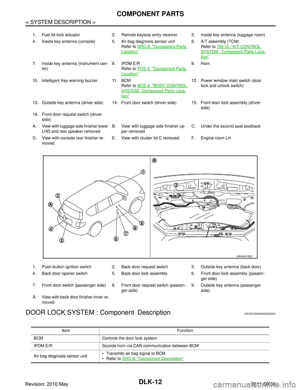
DOOR LOCK SYSTEM : Component Description
INFOID:0000000006225834
1. Fuel lid lock actuator 2. Remote keyless entry receiver 3. Inside key antenna (luggage room)
4. Inside key antenna (console) 5. Air bag diagnosis sensor unit Refer to SRC-8, "
Component Parts
Location"
6. A/T assembly (TCM)
Refer to TM-10, "
A/T CONTROL
SYSTEM : Component Parts Loca-
tion"
7. Inside key antenna (instrument cen-
ter) 8. IPDM E/R
Refer to PCS-4, "
Component Parts
Location"
9. Horn
10. Intelligent Key warning buzzer 11. BCM Refer to BCS-4, "
BODY CONTROL
SYSTEM : Component Parts Loca-
tion"
12. Power window main switch (door
lock and unlock switch)
13. Outside key antenna (driver side) 14. Front door switch (driver side) 15. Front door lock assembly (driver side)
16. Front door request switch (driver side)
A. View with luggage side finisher lower LHD and rear speaker removed B. View with luggage side finisher up-
per removed C. Under the second seat seatback
D. View with console rear finisher re- moved E. View with cluster lid C removed F. Engine room LH
1. Push-button ignition switch 2. Back door request switch 3. Outside key antenna (back door)
4. Back door opener switch 5. Back door lock assembly 6. Front door lock assembly (passen- ger side)
7. Front door switch (passenger side) 8. Front door request switch (passen- ger side)9. Outside key antenna (passenger
side)
A. View with back door finisher inner re- moved
JMKIA5218ZZ
Item Function
BCM Controls the door lock system
IPDM E/R Sounds horn via CAN communication between BCM
Air bag diagnosis sensor unit Transmits air bag signal to BCM
Refer to
SRC-9, "
Component Description"
Revision: 2010 May2011 QX56
Page 1551 of 5598
COMPONENT PARTSDLK-15
< SYSTEM DESCRIPTION >
C
DE
F
G H
I
J
L
M A
B
DLK
N
O P
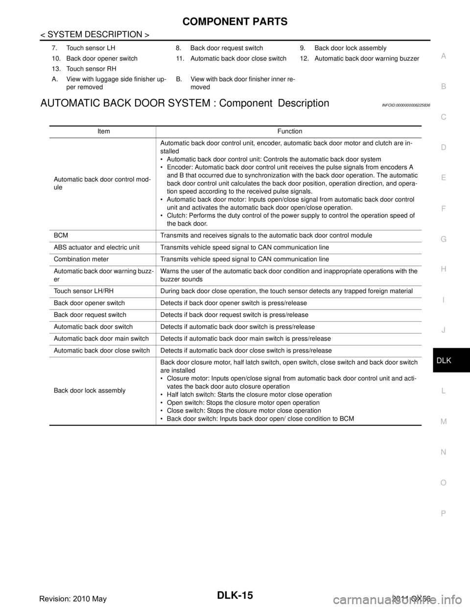
AUTOMATIC BACK DOOR SYST EM : Component DescriptionINFOID:0000000006225836
7. Touch sensor LH 8. Back door request switch 9. Back door lock assembly
10. Back door opener switch 11. Automatic back door close switch 12. Automatic back door warning buzzer
13. Touch sensor RH
A. View with luggage side finisher up-
per removed B. View with back door finisher inner re-
moved
Item Function
Automatic back door control mod-
ule Automatic back door control unit, encoder, automatic back door motor and clutch are in-
stalled
Automatic back door control unit: Controls the automatic back door system
Encoder: Automatic back door control unit receives the pulse signals from encoders A
and B that occurred due to synchronization with the back door operation. The automatic
back door control unit calculates the back door position, operation direction, and opera-
tion speed according to the received pulse signals.
Automatic back door motor: Inputs open/close signal from automatic back door control
unit and activates the automatic back door open/close operation.
Clutch: Performs the duty control of the power supply to control the operation speed of the back door.
BCM Transmits and receives signals to the automatic back door control module
ABS actuator and electric unit Transmits vehi cle speed signal to CAN communication line
Combination meter Transmits vehicle speed signal to CAN communication line
Automatic back door warning buzz-
er Warns the user of the automatic back door condition and inappropriate operations with the
buzzer sounds
Touch sensor LH/RH During back door close operation, the touch sensor detects any trapped foreign material
Back door opener switch Detects if back door opener switch is press/release
Back door request switch Detects if back door request switch is press/release
Automatic back door switch Detects if automatic back door switch is press/release
Automatic back door main switch Detects if automatic back door main switch is press/release
Automatic back door close switch Detects if automatic back door close switch is press/release
Back door lock assembly Back door closure motor, half latch switch, open switch, close switch and back door switch
are installed
Closure motor: Inputs open/close signal from automatic back door control unit and acti-
vates the back door auto closure operation
Half latch switch: Starts the closure motor close operation
Open switch: Stops the closure motor open operation
Close switch: Stops the closure motor close operation
Back door switch: Inputs back door open/ close condition to BCM
Revision: 2010 May2011 QX56