Page 3113 of 5598
![INFINITI QX56 2011 Factory Service Manual
COMPONENT PARTSHAC-7
< SYSTEM DESCRIPTION > [AUTOMATIC AIR CONDITIONING]
C
D
E
F
G H
J
K L
M A
B
HAC
N
O P
FRONT AUTOMATIC AIR CONDITIONING SYSTEM : Component Description
INFOID:0000000006275849
13. INFINITI QX56 2011 Factory Service Manual
COMPONENT PARTSHAC-7
< SYSTEM DESCRIPTION > [AUTOMATIC AIR CONDITIONING]
C
D
E
F
G H
J
K L
M A
B
HAC
N
O P
FRONT AUTOMATIC AIR CONDITIONING SYSTEM : Component Description
INFOID:0000000006275849
13.](/manual-img/42/57033/w960_57033-3112.png)
COMPONENT PARTSHAC-7
< SYSTEM DESCRIPTION > [AUTOMATIC AIR CONDITIONING]
C
D
E
F
G H
J
K L
M A
B
HAC
N
O P
FRONT AUTOMATIC AIR CONDITIONING SYSTEM : Component Description
INFOID:0000000006275849
13. Aspirator 14. Front air mix door motor (Driver side) 15. Intake sensor
16. Front mode door motor 17. Front air mix door motor (Passenger
side)18. Intake door motor
19. Front blower motor 20. A/C auto amp. 21. Front in-vehicle sensor
A. Left side of heater & cooling unit as- sembly B. Right side of heater & cooling unit as-
sembly C. Back side of blower unit assembly
D. Cluster lid C is removed E. Ins trument lower panel LH is re-
moved
Component Description
Ambient sensor Ambient sensor measures ambient air temperature. The sensor uses a
thermistor which is sensitive to the change in temperature. The electrical
resistance of the thermistor decreases as temperature increases.
AV c o n t r o l u n i t AV control unit transmits front A/C control operation signal to A/C auto amp.
via CAN communication line.
A/C auto amp. A/C auto amp. controls front automatic air conditioning system by inputting
and calculating signals from each sensor and each switch. A/C auto amp.
has self-diagnosis function. Diagnosis of front automatic air conditioning
system can be performed quickly.
Blower unit Front blower motor Refer to
HAC-12
.
Intake door motor The LCU (Local Control Unit) is installed to intake door motor so as to per-
form the multiplex commu
nication control (LIN).
Refer to HAC-18, "
FRONT AUTOMATIC AIR CONDITIONING SYSTEM :
Door Control".
Combination meter Combination meter transmits vehicle speed signal to A/C auto amp. via
CAN communication line.
ECM ECM controls compressor according to status of engine and refrigerant.
ECM transmits engine coolant temperature signal to A/C auto amp. via
CAN communication line.
Engine coolant temperature sensor Engine coolant temperature sensor measures engine coolant temperature.
The sensor uses a thermistor which is sensitive to the change in tempera-
ture. The electrical resistance of the thermistor decreases as temperature
increases.
Front display Front display indicates operation status of front automatic air conditioning
system.
Front in-vehicle sensor Front in-vehicle sensor measures temperature of intake air that flows
through aspirator to passenger room. The sensor uses a thermistor which
is sensitive to the change in temperature. The electrical resistance of the
thermistor decreases as temperature increases.
Revision: 2010 May2011 QX56
Page 3115 of 5598
COMPONENT PARTSHAC-9
< SYSTEM DESCRIPTION > [AUTOMATIC AIR CONDITIONING]
C
D
E
F
G H
J
K L
M A
B
HAC
N
O P
REAR AUTOMATIC AIR CONDITIONING SY STEM : Component Parts Location
INFOID:0000000006275850
1. Rear A/C control 2. Preset switch 3. Engine coolant temperature sensor
Refer to EC-16, "
Component Parts
Location".
4. ECM Refer to EC-16, "
Component Parts
Location". 5. Ambient sensor 6. AV control unit
Refer to AV- 9 , "
Component Parts Lo-
cation".
7. Combination meter Refer to MWI-6, "
METER SYSTEM :
Component Parts Location". 8. Sunload sensor 9. Front display
10. Rear mode door motor 11. Rear air mix door motor 12. Rear in-vehicle sensor
13. Rear blower motor 14. Rear A/C solenoid valve 15. Rear A/C relay
16. Intake sensor 17. A/C auto amp.
A. Right side of rear A/C unit assembly B. Left side of rear A/C unit assembly C. Back side of engine room (RH)
D. Left side of heater & cooling unit as- sembly E. Cluster lid C is removed
JMIIA0813ZZ
Revision: 2010 May2011 QX56
Page 3117 of 5598
![INFINITI QX56 2011 Factory Service Manual
COMPONENT PARTSHAC-11
< SYSTEM DESCRIPTION > [AUTOMATIC AIR CONDITIONING]
C
D
E
F
G H
J
K L
M A
B
HAC
N
O P
ACCS (ADVANCED CLIMATE CONTROL SYSTEM) : Component Parts Location
INFOID:0000000006275852
INFINITI QX56 2011 Factory Service Manual
COMPONENT PARTSHAC-11
< SYSTEM DESCRIPTION > [AUTOMATIC AIR CONDITIONING]
C
D
E
F
G H
J
K L
M A
B
HAC
N
O P
ACCS (ADVANCED CLIMATE CONTROL SYSTEM) : Component Parts Location
INFOID:0000000006275852](/manual-img/42/57033/w960_57033-3116.png)
COMPONENT PARTSHAC-11
< SYSTEM DESCRIPTION > [AUTOMATIC AIR CONDITIONING]
C
D
E
F
G H
J
K L
M A
B
HAC
N
O P
ACCS (ADVANCED CLIMATE CONTROL SYSTEM) : Component Parts Location
INFOID:0000000006275852
ACCS (ADVANCED CLIMATE CONTRO L SYSTEM) : Component Description
INFOID:0000000006275853
1. Preset switch 2. Exhaust gas / outside odor detecting
sensor3. AV control unit
Refer to AV- 9 , "
Component Parts Lo-
cation".
4. Front display 5. Ionizer 6. Intake door motor
7. A/C auto amp.
A. Left side of heater & cooling unit as- sembly B. Back side of blower unit assembly C. Cluster lid C is removed
JMIIA0814ZZ
Component Description
Blower unit Intake door motor The LCU (Local Control Unit) is installed to intake door motor so as to per-
form the multiplex communication control (LIN).
Refer to
HAC-18, "
FRONT AUTOMATIC AIR CONDITIONING SYSTEM :
Door Control".
AV c o n t r o l u n i t AV control unit transmits A/C switch operation signal to A/C auto amp. via
CAN communication line.
A/C auto amp. A/C auto amp. controls ACCS (advanced climate control system) by input-
ting and calculating signals from each sensor and each switch. A/C auto
amp. has self-diagnosis function. Diagnosis of ACCS (advanced climate
control system) can be performed quickly.
Exhaust gas / outside odor detecting sensor Exhaust gas / outside odor detecting sensor measures unpleasant odor out-
side of passenger room. In addition to previous exhaust gas detection func-
tion, unpleasant odor in ambient atmosphere is measured.
Revision: 2010 May2011 QX56
Page 3124 of 5598
HAC-18
< SYSTEM DESCRIPTION >[AUTOMATIC AIR CONDITIONING]
SYSTEM
FRONT AUTOMATIC AIR CONDITION ING SYSTEM : Door Control
INFOID:0000000006275866
DOOR MOTOR CONTROL
LCU (Local Control Unit) is built in to each door moto r. And detects door position by PBR (Potentio Balance
Resistor).
A/C auto amp. communicates with each LCU via comm unication line. And receives each door position feed
back signal from each LCU.
Each LCU controls each door to the appropriate pos ition depending on the control signal from A/C auto amp.
when the door movement is complete, transmits the signal of door movement completion to A/C auto amp.
SWITCHES AND THEIR CONTROL FUNCTION
With ACCS (Advanced Climate Control System)
JMIIA0817GB
JMIIA0727ZZ
Revision: 2010 May2011 QX56
Page 3132 of 5598
HAC-26
< SYSTEM DESCRIPTION >[AUTOMATIC AIR CONDITIONING]
SYSTEM
REAR AUTOMATIC AIR CONDITION ING SYSTEM : Door Control
INFOID:0000000006275873
DOOR MOTOR CONTROL
LCU (Local Control Unit) is built in to each door moto r. And detects door position by PBR (Potentio Balance
Resistor).
A/C auto amp. communicates with each LCU via comm unication line. And receives each door position feed
back signal from each LCU.
Each LCU controls each door to the appropriate pos ition depending on the control signal from A/C auto amp.
when the door movement is complete, transmits the signal of door movement completion to A/C auto amp.
SWITCHES AND THEIR CONTROL FUNCTION
JMIIA0729GB
1. Rear blower motor 2. Rear evaporator 3. Rear air mix door
4. Rear heater core 5. Rear mode door
Recirculation air
Rear ventilator Rear A/C foot
Switch/Dial position Door position
Rear mode door Rear air mix door
AUTO switch Front A/C control
AUTO
Rear A/C control
JMIIA0744ZZ
Revision: 2010 May2011 QX56
Page 3271 of 5598

INL-4
< SYSTEM DESCRIPTION >
COMPONENT PARTS
SYSTEM DESCRIPTION
COMPONENT PARTS
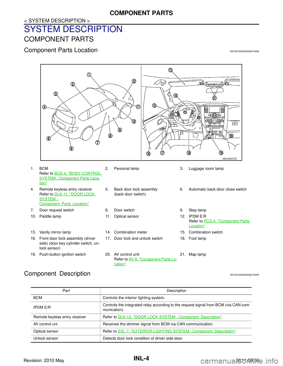
Component Parts LocationINFOID:0000000006216048
Component DescriptionINFOID:0000000006216049
1. BCMRefer to BCS-4, "
BODY CONTROL
SYSTEM : Componen t Parts Loca-
tion"
2. Personal lamp 3. Luggage room lamp
4. Remote keyless entry receiver Refer to DLK-11, "
DOOR LOCK
SYSTEM :
ComponentPartsLocation"
5. Back door lock assembly
(back door switch) 6. Automatic back door close switch
7. Door request switch 8. Door switch 9. Step lamp
10. Paddle lamp 11. Optical sensor 12. IPDM E/R Refer to PCS-4, "
Component Parts
Location"
13. Vanity mirror lamp 14. Combination meter 15. Combination switch
16. Front door lock assembly (driver
side) (door key cylinder switch, un-
lock sensor) 17. Door lock and unlock switch 18. Foot lamp
19. Push-button ignition switch 20. AV control unit Refer to AV- 9 , "
Component Parts Lo-
cation"
21. Map lamp
JMLIA0837ZZ
Part Description
BCM Controls the interior lighting system.
IPDM E/R Controls the integrated relay according to the request signal from BCM (via CAN com-
munication).
Remote keyless entry receiver Refer to DLK-12, "
DOOR LOCK SYSTEM : ComponentDescription".
AV control uni Receives the dimmer signal from BCM via CAN communication.
Optical sensor Refer to EXL-7, "
EXTERIOR LIGHTING SYSTEM : ComponentDescription".
Unlock sensor Detects door lock condition of driver side door.
Revision: 2010 May2011 QX56
Page 3272 of 5598
COMPONENT PARTSINL-5
< SYSTEM DESCRIPTION >
C
DE
F
G H
I
J
K
M A
B
INL
N
O P
Combination switch
(Lighting & turn signal switch) Refer to
BCS-7, "COMBINATION SWITCH READING SYSTEM : System Description".
Door lock and unlock switch
Door request switch
Door key cylinder switch Inputs the lock/unlock signal to BCM.
Door switch
Back door switch Inputs the door switch signal to BCM.
Part Description
Revision: 2010 May2011 QX56
Page 3273 of 5598

INL-6
< SYSTEM DESCRIPTION >
SYSTEM
SYSTEM
INTERIOR ROOM LAMP CONTROL SYSTEM
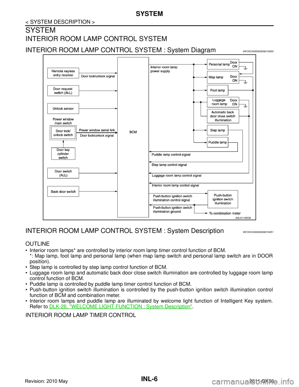
INTERIOR ROOM LAMP CONTROL SYSTEM : System DiagramINFOID:0000000006216050
INTERIOR ROOM LAMP CONTROL SYSTEM : System DescriptionINFOID:0000000006216051
OUTLINE
Interior room lamps* are controlled by interi or room lamp timer control function of BCM.
*: Map lamp, foot lamp and personal lamp (when map lamp switch and personal lamp switch are in DOOR
position).
Step lamp is controlled by step lamp control function of BCM.
Luggage room lamp and automatic back door close switch illumination are controlled by luggage room lamp
control function of BCM.
Puddle lamp is controlled by puddle lamp timer control function of BCM.
Push-button ignition switch illumination is controlled by the push-button ignition switch illumination control
function of BCM and combination meter.
Interior room lamps and puddle lamp are illuminated by welcome light function of Intelligent Key system.
Refer to DLK-26, "
WELCOME LIGHT FUNCTION : System Description".
INTERIOR ROOM LAMP TIMER CONTROL
JMLIA1188GB
Revision: 2010 May2011 QX56