Page 5524 of 5598
COMPONENT PARTSWW-5
< SYSTEM DESCRIPTION >
C
DE
F
G H
I
J
K
M A
B
WW
N
O P
SYSTEM DESCRIPTION
COMPONENT PARTS
Component Parts LocationINFOID:0000000006300448
1. IPDM E/R Refer to PCS-4, "
Component Parts
Location"
2. BCM
Refer to BCS-4, "
BODY CONTROL
SYSTEM : Component Parts Loca-
tion"
3. TCM
Refer to TM-10, "
A/T CONTROL
SYSTEM : Componen t Parts Loca-
tion"
4. Light & rain sensor 5. Combination switch 6. Washer level switch
7. Washer pump 8. Headlamp washer pump 9. Headlamp washer relay
10. Front wiper motor 11. Rear wiper motor
A. Behind front fender protector (RH) B. Engine room (LH) C. Cowl top, left side of engine room
D. Back door finisher inside
JMLIA0976ZZ
Revision: 2010 May2011 QX56
Page 5533 of 5598

WW-14
< SYSTEM DESCRIPTION >
DIAGNOSIS SYSTEM (BCM)
DIAGNOSIS SYSTEM (BCM)
COMMON ITEM
COMMON ITEM : CONSULT-III Function (BCM - COMMON ITEM)INFOID:0000000006349813
APPLICATION ITEM
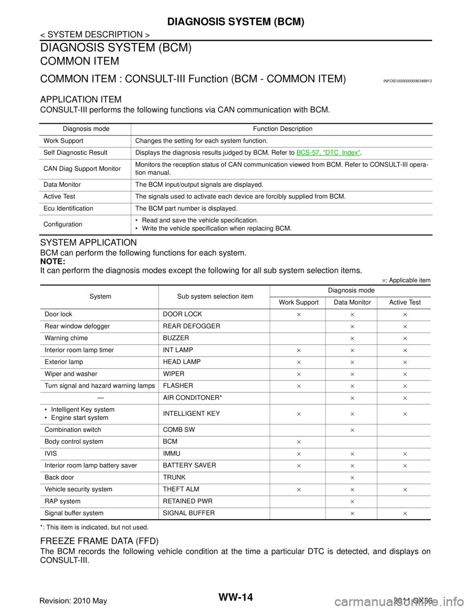
CONSULT-III performs the following functions via CAN communication with BCM.
SYSTEM APPLICATION
BCM can perform the following functions for each system.
NOTE:
It can perform the diagnosis modes except the following for all sub system selection items.
×: Applicable item
*: This item is indicated, but not used.
FREEZE FRAME DATA (FFD)
The BCM records the following vehicle condition at the time a particular DTC is detected, and displays on
CONSULT-III.
Diagnosis mode Function Description
Work Support Changes the setting for each system function.
Self Diagnostic Result Displays the diagnosis results judged by BCM. Refer to BCS-57, "
DTCIndex".
CAN Diag Support Monitor Monitors the reception status of CAN communication viewed from BCM. Refer to CONSULT-III opera-
tion manual.
Data Monitor The BCM input/output signals are displayed.
Active Test The signals used to activate ea ch device are forcibly supplied from BCM.
Ecu Identification The BCM part number is displayed.
Configuration Read and save the vehicle specification.
Write the vehicle specification when replacing BCM.
System Sub system selection item Diagnosis mode
Work Support Data Monitor Active Test
Door lock DOOR LOCK ×××
Rear window defogger REAR DEFOGGER ××
Warning chime BUZZER ××
Interior room lamp timer INT LAMP ×××
Exterior lamp HEAD LAMP ×××
Wiper and washer WIPER ×××
Turn signal and hazard warning lamps FLASHER ×××
— AIR CONDITONER* ××
Intelligent Key system
Engine start system INTELLIGENT KEY
×××
Combination switch COMB SW ×
Body control system BCM ×
IVIS IMMU ×××
Interior room lamp battery saver BATTERY SAVER ×××
Back door TRUNK ×
Vehicle security system THEFT ALM ×××
RAP system RETAINED PWR ×
Signal buffer system SIGNAL BUFFER ××
Revision: 2010 May2011 QX56
Page 5593 of 5598

WW-74
< REMOVAL AND INSTALLATION >
REAR WIPER ARM
REAR WIPER ARM
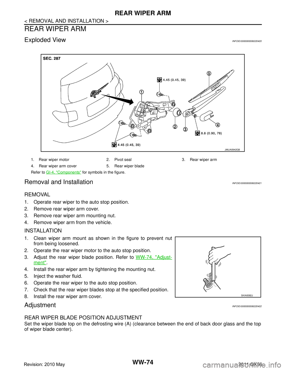
Exploded ViewINFOID:0000000006220420
Removal and InstallationINFOID:0000000006220421
REMOVAL
1. Operate rear wiper to the auto stop position.
2. Remove rear wiper arm cover.
3. Remove rear wiper arm mounting nut.
4. Remove wiper arm from the vehicle.
INSTALLATION
1. Clean wiper arm mount as shown in the figure to prevent nutfrom being loosened.
2. Operate the rear wiper motor to the auto stop position.
3. Adjust the rear wiper blade position. Refer to WW-74, "
Adjust-
ment".
4. Install the rear wiper arm by tightening the mounting nut.
5. Inject the washer fluid.
6. Operate the rear wiper to the auto stop position.
7. Check that the rear wiper blades stop at the specified position.
8. Install the rear wiper arm cover.
AdjustmentINFOID:0000000006220422
REAR WIPER BLADE POSITION ADJUSTMENT
Set the wiper blade top on the defrosting wire (A) (c learance between the end of back door glass and the top
of wiper blade center).
1. Rear wiper motor 2. Pivot seal 3. Rear wiper arm
4. Rear wiper arm cover 5. Rear wiper blade
Refer to GI-4, "
Components" for symbols in the figure.
JMLIA0942GB
SKIA0082J
Revision: 2010 May2011 QX56
Page 5595 of 5598
WW-76
< REMOVAL AND INSTALLATION >
REAR WIPER MOTOR
REAR WIPER MOTOR
Exploded ViewINFOID:0000000006220423
Removal and InstallationINFOID:0000000006220424
REMOVAL
1. Remove rear wiper arm. Refer to WW-74, "Removal and Installation".
2. Remove back door finisher inner. Refer to INT-39, "
Removal and Installation".
3. Disconnect rear wiper motor connector.
4. Remove rear wiper motor mounting bolts.
5. Remove rear wiper motor from the vehicle.
6. Remove the pivot seal.
INSTALLATION
Install in the reverse order of removal.
1. Rear wiper motor 2. Pivot seal 3. Rear wiper arm
4. Rear wiper arm cover 5. Rear wiper blade
Refer to GI-4, "
Components" for symbols in the figure.
JMLIA0942GB
Revision: 2010 May2011 QX56