2011 INFINITI QX56 drain bolt
[x] Cancel search: drain boltPage 371 of 5598

AV
BOSE AMP.AV-223
< REMOVAL AND INSTALLATION >
C
DE
F
G H
I
J
K L
M B A
O P
BOSE AMP.
Removal and InstallationINFOID:0000000006216389
REMOVAL
1. Remove rear ventilator duct lower. Refer to HA-46, "Exploded View".
2. Remove shield bracket. Refer to SR-24, "
Exploded View".
3. Remove rear drain hose clip. Obtain a service area. Refer to RF-37, "
Exploded View".
4. Remove BOSE amp. mounting bolts.
5. Disconnect BOSE amp. connecto r to remove BOSE amp.
INSTALLATION
Install in the reverse order of removal.
Revision: 2010 May2011 QX56
Page 493 of 5598
BRAKE PIPINGBR-23
< REMOVAL AND INSTALLATION >
C
DE
G H
I
J
K L
M A
B
BR
N
O P
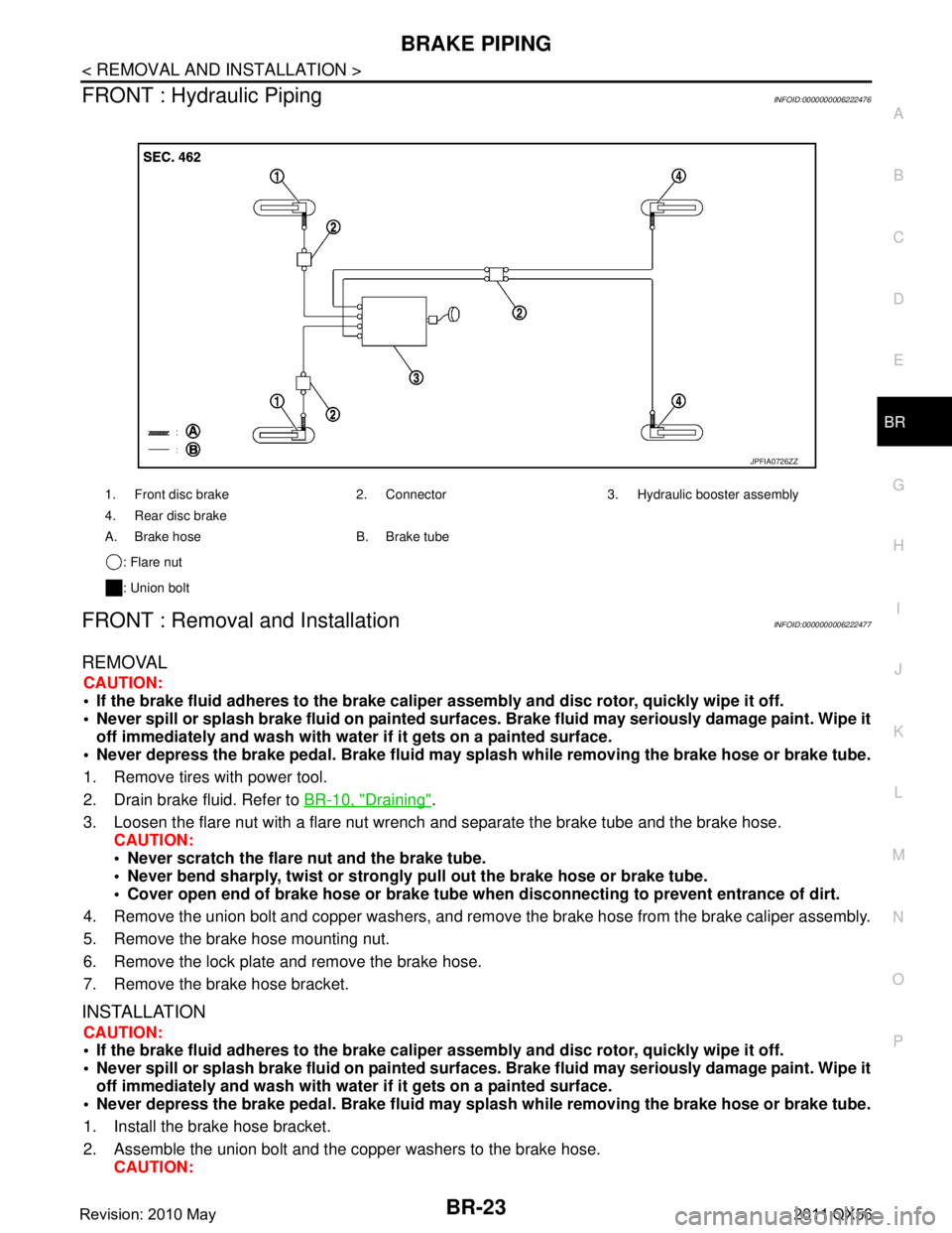
FRONT : Hydraulic PipingINFOID:0000000006222476
FRONT : Removal and InstallationINFOID:0000000006222477
REMOVAL
CAUTION:
If the brake fluid adheres to the brake caliper assembly and disc rotor, quickly wipe it off.
Never spill or splash brake fluid on painted surfaces. Brake fluid may seriously damage paint. Wipe it
off immediately and wash with wate r if it gets on a painted surface.
Never depress the brake pedal. Brake fluid may spl ash while removing the brake hose or brake tube.
1. Remove tires with power tool.
2. Drain brake fluid. Refer to BR-10, "
Draining".
3. Loosen the flare nut with a flare nut wrench and separate the brake tube and the brake hose.
CAUTION:
Never scratch the flare nut and the brake tube.
Never bend sharply, twist or strongly pull out the brake hose or brake tube.
Cover open end of brake hose or brake tube wh en disconnecting to prevent entrance of dirt.
4. Remove the union bolt and copper washers, and remove the brake hose from the brake caliper assembly.
5. Remove the brake hose mounting nut.
6. Remove the lock plate and remove the brake hose.
7. Remove the brake hose bracket.
INSTALLATION
CAUTION:
If the brake fluid adheres to the brake caliper assembly and disc rotor, quickly wipe it off.
Never spill or splash brake fluid on painted surfaces. Brake fluid may seriously damage paint. Wipe it
off immediately and wash with wate r if it gets on a painted surface.
Never depress the brake pedal. Brake fluid may spl ash while removing the brake hose or brake tube.
1. Install the brake hose bracket.
2. Assemble the union bolt and the copper washers to the brake hose. CAUTION:
1. Front disc brake 2. Connector 3. Hydraulic booster assembly
4. Rear disc brake
A. Brake hose B. Brake tube
: Flare nut
: Union bolt
JPFIA0726ZZ
Revision: 2010 May2011 QX56
Page 496 of 5598
BR-26
< REMOVAL AND INSTALLATION >
BRAKE PIPING
REAR : Removal and Installation
INFOID:0000000006222481
REMOVAL
CAUTION:
If the brake fluid adheres to the brake caliper assembly and disc rotor, quickly wipe it off.
Never spill or splash brake fluid on painted surfaces. Brake fluid may seriously damage paint. Wipe it
off immediately and wash with wate r if it gets on a painted surface.
Never depress the brake pedal. Brake fluid may spl ash while removing the brake hose or brake tube.
1. Remove tires with power tool.
2. Drain brake fluid. Refer to BR-10, "
Draining".
3. Loosen the flare nut with a flare nut wrench and separate the brake tube and the brake hose. CAUTION:
Never scratch the flare nut and the brake tube.
Never bend sharply, twist or strongly pull out the brake hose or brake tube.
Cover open end of brake hose or brake tube wh en disconnecting to prevent entrance of dirt.
4. Remove the union bolt and copper washers, and remove the brake hose from the brake caliper assembly.
5. Remove the lock plate and remove the brake hose.
INSTALLATION
CAUTION:
If the brake fluid adheres to the brake caliper assembly and disc rotor, quickly wipe it off.
Never spill or splash brake fluid on painted surfaces. Brake fluid may seriously damage paint. Wipe it
off immediately and wash with wate r if it gets on a painted surface.
Never depress the brake pedal. Brake fluid may spl ash while removing the brake hose or brake tube.
1. Assemble the union bolt and the copper washers to the brake hose. CAUTION:
Never reuse the copper washer.
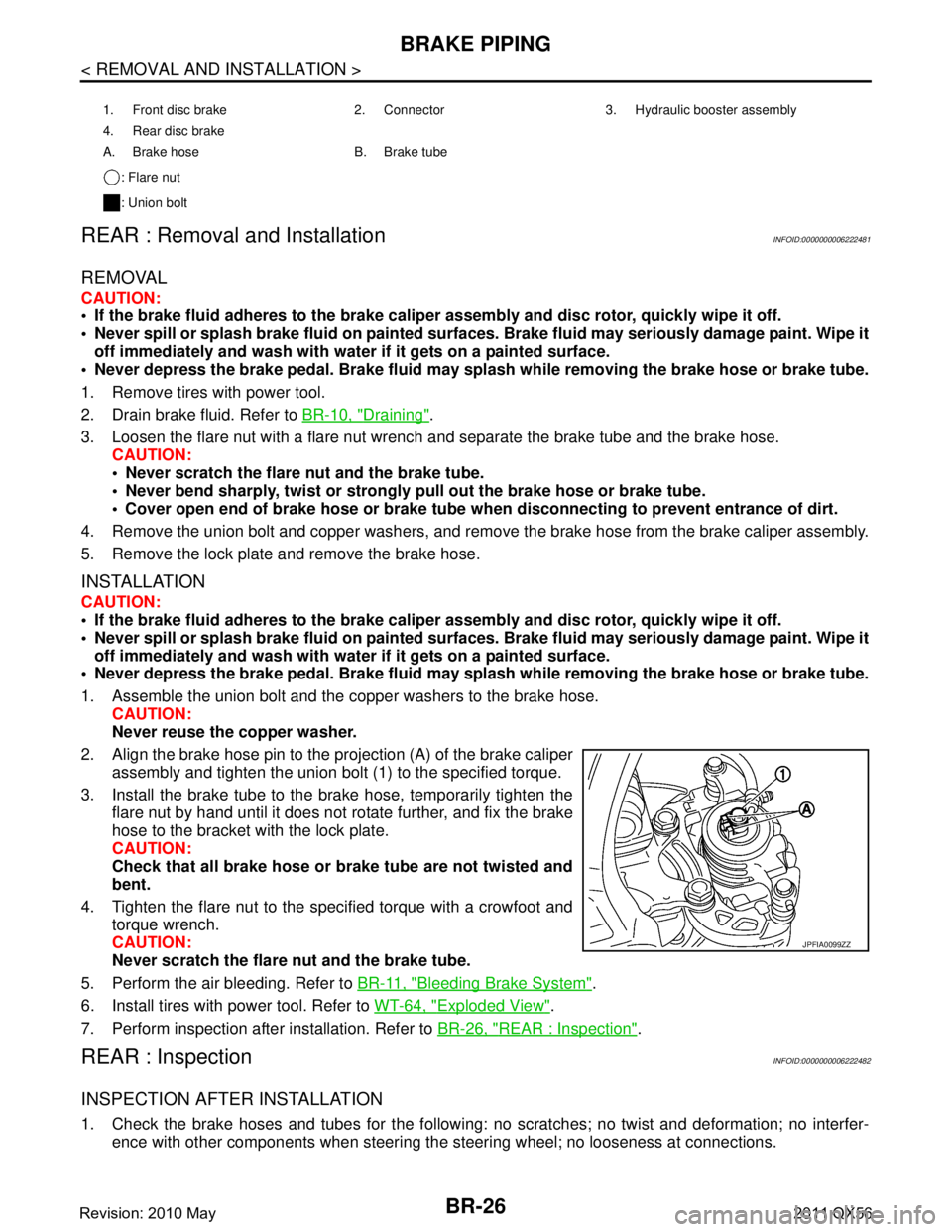
2. Align the brake hose pin to the projection (A) of the brake caliper
assembly and tighten the union bolt (1) to the specified torque.
3. Install the brake tube to the brake hose, temporarily tighten the flare nut by hand until it does not rotate further, and fix the brake
hose to the bracket with the lock plate.
CAUTION:
Check that all brake hose or brake tube are not twisted and
bent.
4. Tighten the flare nut to the specified torque with a crowfoot and torque wrench.
CAUTION:
Never scratch the flare nut and the brake tube.
5. Perform the air bleeding. Refer to BR-11, "
Bleeding Brake System".
6. Install tires with power tool. Refer to WT-64, "
Exploded View".
7. Perform inspection after installation. Refer to BR-26, "
REAR : Inspection".
REAR : InspectionINFOID:0000000006222482
INSPECTION AFTER INSTALLATION
1. Check the brake hoses and tubes for the following: no scratches; no twist and deformation; no interfer-
ence with other components when steering the steering wheel; no looseness at connections.
1. Front disc brake 2. Connector 3. Hydraulic booster assembly
4. Rear disc brake
A. Brake hose B. Brake tube
: Flare nut
: Union bolt
JPFIA0099ZZ
Revision: 2010 May2011 QX56
Page 507 of 5598

FRONT DISC BRAKEBR-37
< REMOVAL AND INSTALLATION >
C
DE
G H
I
J
K L
M A
B
BR
N
O P
BRAKE CALIPER ASSEMBLY : Removal and InstallationINFOID:0000000006222492
REMOVAL
WARNING:
Clean any dust from the brake caliper assembly an d brake pads with a vacuum dust collector. Never
blow with compressed air.
CAUTION:
Never spill or splash brake fluid on painted surfaces. Brake fluid may seriously damage paint. Wipe it
off immediately and wash with wate r if it gets on a painted surface.
Never depress the brake pedal. Brake fluid m ay splash while removing the brake hose.
If the brake fluid or grease adheres to the brake cal iper assembly and disc rotor, quickly wipe it off.
1. Remove tires with power tool.
2. Fix the disc rotor using wheel nuts.
3. Drain brake fluid. Refer to BR-10, "
Draining".
4. Separate brake hose from brake caliper assembly. Refer to BR-23, "
FRONT : Removal and Installation".
5. Remove torque member mounting bolts, and remove brake caliper assembly. CAUTION:
Never drop brake pad and brake caliper assembly.
6. Remove disc rotor. Refer to FA X - 8 , "
Removal and Installation" (2WD), FAX-18, "Removal and Installation"
(AWD).
INSTALLATION
WARNING:
Clean any dust from the brake caliper assembly an d brake pads with a vacuum dust collector. Never
blow with compressed air.
CAUTION:
Never spill or splash brake fluid on painted surfaces. Brake fluid may seriously damage paint. Wipe it
off immediately and wash with wate r if it gets on a painted surface.
Never depress the brake pedal. Brake fluid m ay splash while removing the brake hose.
If the brake fluid or grease adheres to the brake cal iper assembly and disc rotor, quickly wipe it off.
1. Torque member 2. Sliding pin boot 3. Sliding pin
4. Piston boot 5. Piston 6. Piston seal
7. Cylinder body 8. Bleeder valve 9. Cap
: Apply rubber grease.
: Apply brake fluid.
Refer to GI-4, "
Components" for symbols not described on the above.
JPFIA0800GB
Revision: 2010 May2011 QX56
Page 514 of 5598
BR-44
< REMOVAL AND INSTALLATION >
REAR DISC BRAKE
CAUTION:
Never spill or splash brake fluid on painted surfaces. Brake fluid may seriously damage paint. Wipe it
off immediately and wash with wate r if it gets on a painted surface.
Never depress the brake pedal. Brake fluid may splash while removing the brake hose.
If the brake fluid or grease adheres to the brake calip er assembly and disc rotor, quickly wipe it off.
1. Remove tires with power tool.
2. Fix the disc rotor using wheel nuts.
3. Drain brake fluid. Refer to BR-10, "
Draining".
4. Separate brake hose from brake caliper assembly. Refer to BR-26, "
REAR : Removal and Installation".
5. Remove torque member mounting bolts, and remove brake caliper assembly. CAUTION:
Never drop brake pad and caliper assembly.
6. Remove disc rotor. Refer to RAX-7, "
Removal and Installation".
INSTALLATION
WARNING:
Clean any dust from the brake caliper assembly an d brake pads with a vacuum dust collector. Never
blow with compressed air.
CAUTION:
Never spill or splash brake fluid on painted surfaces. Brake fluid may seriously damage paint. Wipe it
off immediately and wash with wate r if it gets on a painted surface.
Never depress the brake pedal. Brake fluid may splash while removing the brake hose.
If the brake fluid or grease adheres to the brake calip er assembly and disc rotor, quickly wipe it off.
1. Install disc rotor. Refer to RAX-7, "
Removal and Installation".
2. Install the brake caliper assembly to the axle hous ing and tighten the torque member mounting bolts to the
specified torque.
CAUTION:
Never spill or splash any grease and moisture on the brake caliper assembly mounting face,
threads, mounting bolts. Wipe out any grease and moisture.
3. Install brake hose to brake caliper assembly. Refer to BR-26, "
REAR : Removal and Installation".
4. Perform the air bleeding. Refer to BR-11, "
Bleeding Brake System".
5. Check a drag of rear disc brake. If any drag is found, refer to BR-45, "
BRAKE CALIPER ASSEMBLY :
Inspection".
6. Install tires with power tool. Refer to WT-64, "
Exploded View".
BRAKE CALIPER ASSEMBLY : Disassembly and AssemblyINFOID:0000000006222500
DISASSEMBLY
NOTE:
Never remove the torque member, brake pads and pad retainers when disassembling and assembling the cyl-
inder body.
1. Remove the sliding pin bolt, and remove the cylinder body from the torque member.
CAUTION:
Fix the brake pad at suitable tape so that the brake pad will not drop.
2. Remove sliding pin boots from torque member.
3. Remove bushing from sliding pin bolt.
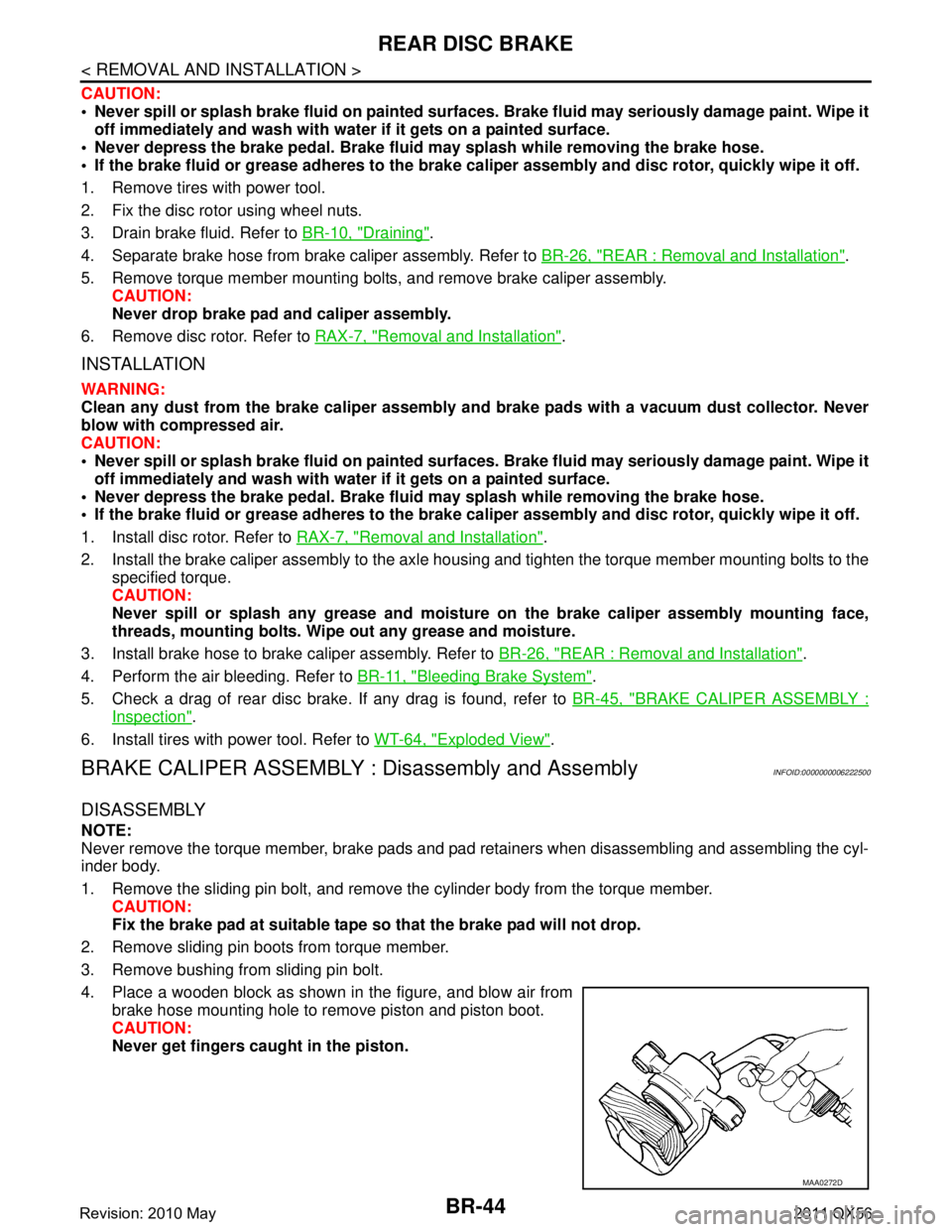
4. Place a wooden block as shown in the figure, and blow air from brake hose mounting hole to remove piston and piston boot.
CAUTION:
Never get fingers caught in the piston.
MAA0272D
Revision: 2010 May2011 QX56
Page 956 of 5598

CO-14
< REMOVAL AND INSTALLATION >
RADIATOR
to release built-up pressure. Carefully remove radiator cap by turning it all the way. Note that the reser-
voir tank cap side is also under pressure.
1. Remove front under cover with power tool. Refer to EXT-25, "
Exploded View".
2. Remove engine cover. Refer to EM-25, "
Exploded View".
3. Drain engine coolant from radiator. Refer to CO-8, "
Draining".
CAUTION:
Perform this step when the engine is cold.
Never spill engine coolant on drive belts.
4. Remove radiator hose (lower).
5. Remove fan shroud (lower). Refer to CO-13, "
Exploded View".
6. Move reservoir tank to the position without the hindrance for work.
7. Remove radiator core support cover. Refer to DLK-220, "
Exploded View".
8. Remove fan shroud (upper), refer to following.
a. Remove EVAP hose mounting bolts and move harness to aside.
b. Move air cleaner case to the position without the hindrance for work. Refer to EM-27, "
Exploded View".
NOTE:
The air cleaner case connector is not required to be disconnected.
9. Remove radiator grille. Refer to EXT-19, "
Exploded View".
10. Move condenser to the position without the hindranc e for work with the following procedures. Refer to HA-
38, "Exploded View".
Remove mounting bolts and disconnect A/C piping from radiator.
Remove air guide from radiator. Refer to EXT-12, "
Exploded View".
Remove radiator mounting bolts.
11. Remove radiator hose (upper).
12. Remove radiator as per the following: CAUTION:
Be careful not to damage radiator core.
Lift up and pull the radiator (1) forward, and then remove themounting rubber (lower) (3) from the radiator core support (2).
INSTALLATION
Note the following, and install in the reverse order of removal.
CAUTION:
Use genuine mounting bolts for th e cooling fan assembly and strictly observe the tightening torque.
(Breakage prevention for radiator)
NOTE:
Insert the radiator hose (1) all the way to the st opper (2) or by 33 mm (1.30 in) (hose without a stopper).
: Vehicle front
JPBIA3431ZZ
JPBIA4294GB
Revision: 2010 May2011 QX56
Page 1768 of 5598
DLK-232
< REMOVAL AND INSTALLATION >
BACK DOOR
BACK DOOR
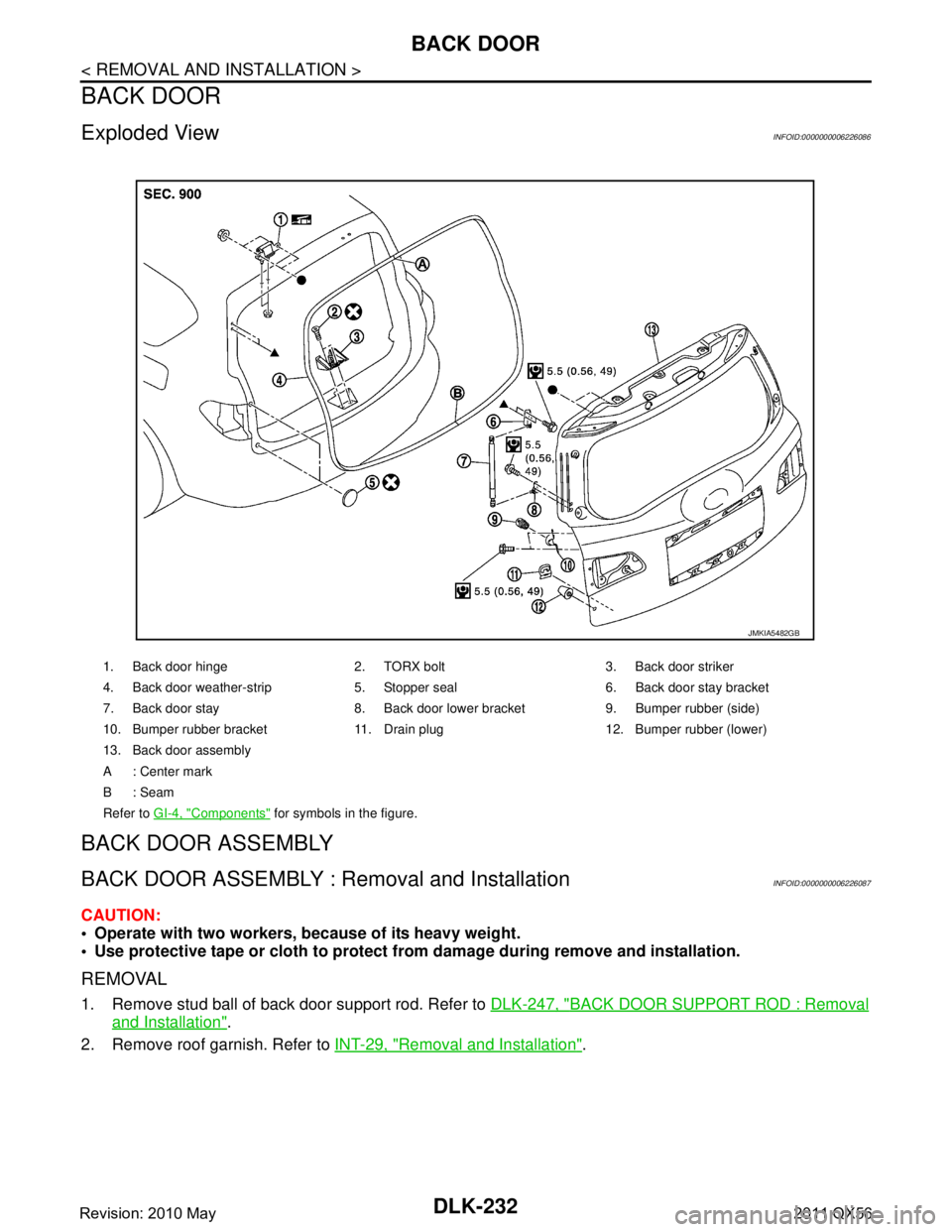
Exploded ViewINFOID:0000000006226086
BACK DOOR ASSEMBLY
BACK DOOR ASSEMBLY : Removal and InstallationINFOID:0000000006226087
CAUTION:
Operate with two workers, because of its heavy weight.
Use protective tape or cloth to protect fr om damage during remove and installation.
REMOVAL
1. Remove stud ball of back door support rod. Refer to DLK-247, "BACK DOOR SUPPORT ROD : Removal
and Installation".
2. Remove roof garnish. Refer to INT-29, "
Removal and Installation".
1. Back door hinge 2. TORX bolt 3. Back door striker
4. Back door weather-strip 5. Stopper seal 6. Back door stay bracket
7. Back door stay 8. Back door lower bracket 9. Bumper rubber (side)
10. Bumper rubber bracket 11. Drain plug 12. Bumper rubber (lower)
13. Back door assembly
A : Center mark
B: Seam
Refer to GI-4, "
Components" for symbols in the figure.
JMKIA5482GB
Revision: 2010 May2011 QX56
Page 1788 of 5598
DLK-252
< REMOVAL AND INSTALLATION >
CAB MOUNTING INSULATOR
Drain brake fluid from brake line. Refer to BR-10, "Draining".
Release fuel pressure. Refer to EC-153, "
Work Procedure".
Disconnect both battery cables. Refer to PG-164, "
Removal and Installation".
Drain engine coolant from radiator. Refer to CO-8, "
Draining".
Discharge refrigerant from A/C circuit. Refer to HA-20, "
Recycle Refrigerant".
Drain power steering fluid from reservoir tank.
4. Remove parts relating to connection of body assembly and frame assembly. Tire and wheel: Refer to WT-64, "
Removal and Installation" (with TPMS).
Front fender protector (LH and RH): Refer to EXT-23, "
FENDER PROTECTOR : Removal and Installa-
tion".
Front bumper: Refer to EXT-13, "
Removal and Installation".
Radiator core support upper: Refer to DLK-220, "
Removal and Installation".
Fan shroud: Refer to CO-16, "
Removal and Installation".
Battery and battery case: Refer to PG-164, "
Removal and Installation".
Air cleaner case (upper and lower): Refer to EM-27, "
Removal and Installation".
Engine cover: Refer to EM-25, "
Removal and Installation".
Rear wheel house protector (LH and RH): EXT-24, "
REAR WHEEL HOUSE PROTECTOR : Removal
and Installation".
Rear bumper: Refer to EXT-17, "
Removal and Installation".
Fuel filler tube: Remove to FL-8, "
Exploded View".
Spare tire
Towing hook bracket.
5. Separate parts relating to connection of body assembly and frame assembly. Vehicle front
Disconnect ICC sensor connector. (models with ICC) Refer to CCS-176, "
Removal and Installation".
Remove radiator upper hose and radiator lower hose from radiator assembly. Refer to CO-13,
"Exploded View".
Remove A/T fluid cooler hose B and A/T fluid cooler hose E from A/T fluid cooler tubes. Refer to TM-
202, "Exploded View".
Remove power steering return hose from oil cooler, and then power steering return hose clamp bolt from frame assembly. Refer to ST-54, "
Exploded View".
Remove power steering suction hose from reservoir tank. Refer to ST-54, "
Exploded View".
CAUTION:
Never spill power steering fluid in engine room.
Remove A/C low-presser flexible hose from A/C low-presser pipe. Refer to HA-35, "
LOW-PRESSURE
FLEXIBLE HOSE : Removal and Installation".
Remove A/C hi-presser flexible hose from condenser. Refer to HA-34, "
HIGH-PRESSURE FLEXIBLE
HOSE : Removal and Installation".
Remove all engine Control Harness connectors, har ness clips and others that are connected to the
body assembly side of the engine room. (engine room LH and RH side). Refer to PG-148, "
Engine Con-
trol Harness".
NOTE:
Separate harness connectors from ECM (engine control module). Refer to EC-10, "
General Precau-
tions".
CAUTION:
When pulling out harnesses, never damage harnesses or connectors.
After temporarily securing connectors, cover th em with vinyl or similar material to protect
against adhesion of foreign materials.
Disconnect engine room harness connectors and remo ve harness clips from engine assembly (engine
RH side). Refer to PG-146, "
Engine Room Harness".
Remove heater hoses from front water outlet tube (engine room RH side). Refer to HA-33, "
Exploded
View".
Disconnect front wheel sensor connectors (LH and RH). Refer to BRC-134, "
FRONT WHEEL SENSOR
: Exploded View".
Disconnect fuel feed tube and EVAP hos e (front wheel well LH side).
Remove steering lower shaft from steering gear side assembly. Refer to ST-37, "
Removal and Installa-
tion"
CAUTION:
Spiral cable may be cut if steering wheel turns while separating steering column assembly and
steering gear assembly.
Revision: 2010 May2011 QX56