2011 INFINITI QX56 drain bolt
[x] Cancel search: drain boltPage 2617 of 5598
OIL PAN (LOWER) AND OIL STRAINEREM-55
< REMOVAL AND INSTALLATION >
C
DE
F
G H
I
J
K L
M A
EM
NP
O
Removal and InstallationINFOID:0000000006289560
REMOVAL
WARNING:
To avoid the danger of being scalded, never
drain engine oil when engine is hot.
1. Drain engine oil. Refer to LU-8, "
Draining".
2. Remove protector A and protector B. Refer to SCS-32, "
FRONT TUBE ASSEMBLY : Exploded View".
3. Remove front suspension rear cross member. Refer to TM-205, "
2WD : Exploded View" (2WD models) or
TM-208, "
4WD : Exploded View" (4WD models).
4. Remove oil pan (lower) as per the following:
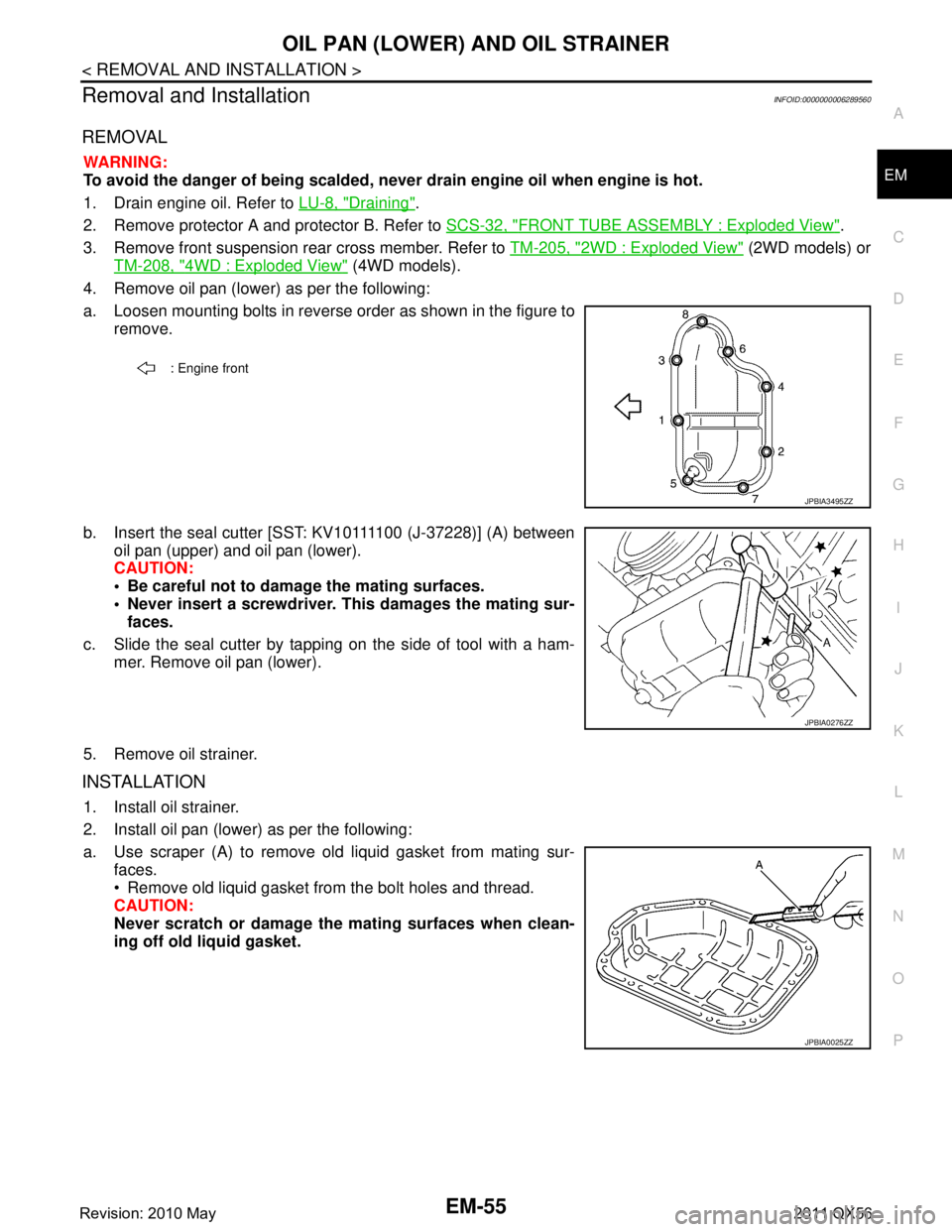
a. Loosen mounting bolts in reverse order as shown in the figure to remove.
b. Insert the seal cutter [SST: KV10111100 (J-37228)] (A) between oil pan (upper) and oil pan (lower).
CAUTION:
Be careful not to damage the mating surfaces.
Never insert a screwdriver. This damages the mating sur-faces.
c. Slide the seal cutter by tapping on the side of tool with a ham- mer. Remove oil pan (lower).
5. Remove oil strainer.
INSTALLATION
1. Install oil strainer.
2. Install oil pan (lower) as per the following:
a. Use scraper (A) to remove old liquid gasket from mating sur- faces.
Remove old liquid gasket from the bolt holes and thread.
CAUTION:
Never scratch or damage th e mating surfaces when clean-
ing off old liquid gasket.
: Engine front
JPBIA3495ZZ
JPBIA0276ZZ
JPBIA0025ZZ
Revision: 2010 May2011 QX56
Page 2618 of 5598
EM-56
< REMOVAL AND INSTALLATION >
OIL PAN (LOWER) AND OIL STRAINER
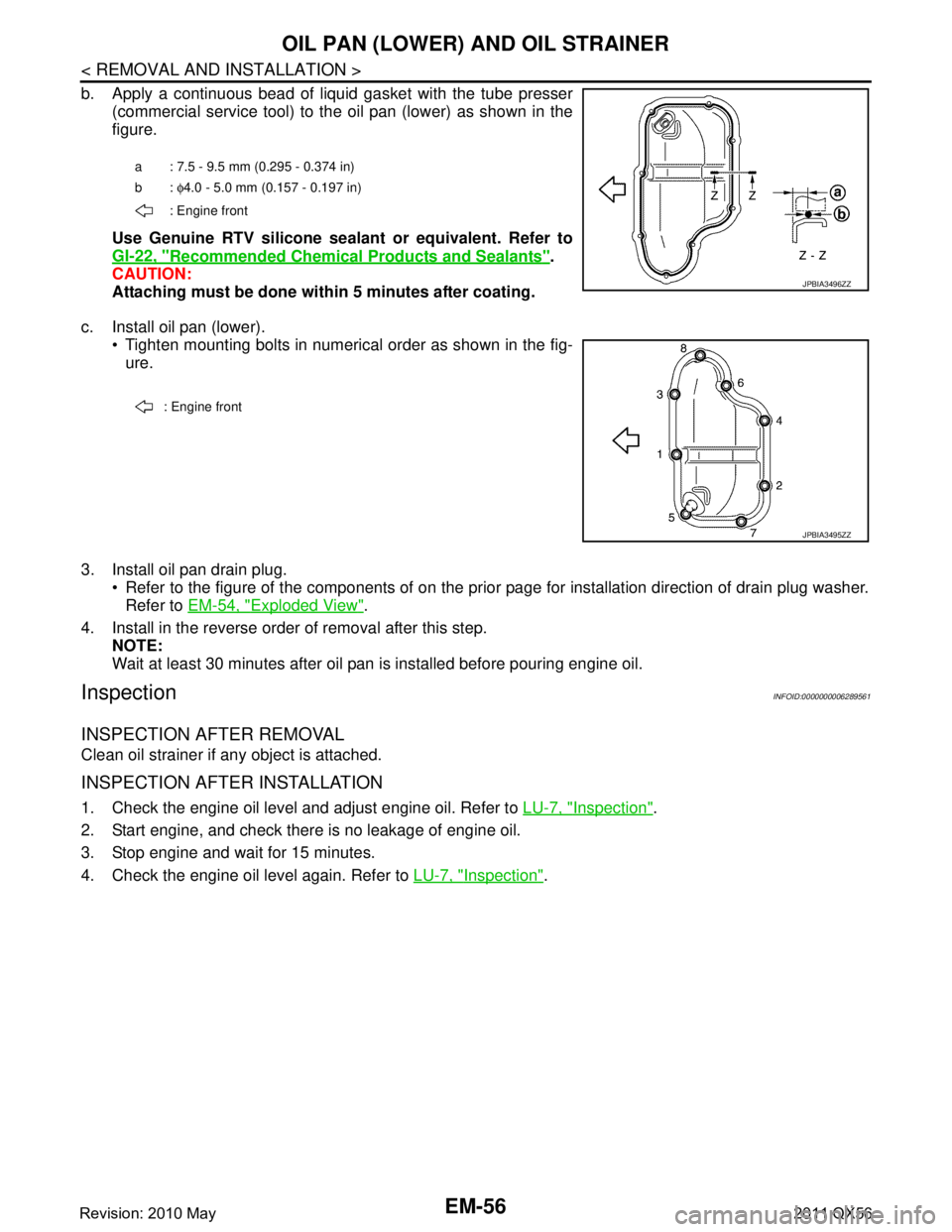
b. Apply a continuous bead of liquid gasket with the tube presser(commercial service tool) to the oil pan (lower) as shown in the
figure.
Use Genuine RTV silicone seal ant or equivalent. Refer to
GI-22, "
Recommended Chemical Products and Sealants".
CAUTION:
Attaching must be done with in 5 minutes after coating.
c. Install oil pan (lower). Tighten mounting bolts in numerical order as shown in the fig-ure.
3. Install oil pan drain plug. Refer to the figure of the components of on the prior page for installation direction of drain plug washer.Refer to EM-54, "
Exploded View".
4. Install in the reverse order of removal after this step. NOTE:
Wait at least 30 minutes after oil pan is installed before pouring engine oil.
InspectionINFOID:0000000006289561
INSPECTION AFTER REMOVAL
Clean oil strainer if any object is attached.
INSPECTION AFTER INSTALLATION
1. Check the engine oil level and adjust engine oil. Refer to LU-7, "Inspection".
2. Start engine, and check there is no leakage of engine oil.
3. Stop engine and wait for 15 minutes.
4. Check the engine oil level again. Refer to LU-7, "
Inspection".
a : 7.5 - 9.5 mm (0.295 - 0.374 in)
b: φ4.0 - 5.0 mm (0.157 - 0.197 in)
: Engine front
JPBIA3496ZZ
: Engine front
JPBIA3495ZZ
Revision: 2010 May2011 QX56
Page 2620 of 5598
EM-58
< REMOVAL AND INSTALLATION >
OIL PAN (UPPER)
Removal and Installation
INFOID:0000000006289563
REMOVAL
WARNING:
To avoid the danger of being scalded, never drain engine oil when engine is hot.
1. Remove oil filter. Refer to LU-9, "
Removal and Installation".
2. Remove oil cooler. Refer to LU-11, "
Exploded View".
3. Move A/C compressor to the position without the hindrance for work. Refer to HA-30, "
Exploded View".
4. Remove oil level gauge and oil level gauge guide.
5. Remove oil pressure switch and oil temperature sensor if necessary.
6. Remove rear plate cover.
7. Remove protector A and protector B. Refer to SCS-32, "
FRONT TUBE ASSEMBLY : Exploded View".
8. Remove front suspension rear cross member. Refer to TM-205, "
2WD : Exploded View" (2WD models) or
TM-208, "
4WD : Exploded View" (4WD models).
9. Remove steering gear assembly. Refer to ST-41, "
Exploded View".
10. Remove front final drive assembly. Refer to DLN-162, "
Exploded View".
11. Remove oil pan (lower). Refer to EM-54, "
Exploded View".
12. Remove oil strainer. Refer to EM-54, "
Exploded View".
13. Remove bolts fixing oil pan (upper) to transmission assembly.
14. Remove oil pan (upper) as per the following:
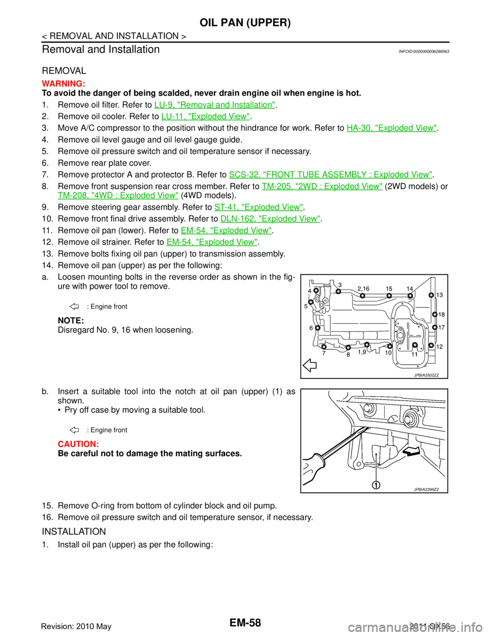
a. Loosen mounting bolts in the reverse order as shown in the fig- ure with power tool to remove.
NOTE:
Disregard No. 9, 16 when loosening.
b. Insert a suitable tool into the notch at oil pan (upper) (1) as shown.
Pry off case by moving a suitable tool.
CAUTION:
Be careful not to damage the mating surfaces.
15. Remove O-ring from bottom of cylinder block and oil pump.
16. Remove oil pressure switch and oil temperature sensor, if necessary.
INSTALLATION
1. Install oil pan (upper) as per the following:
: Engine front
JPBIA3502ZZ
: Engine front
JPBIA2299ZZ
Revision: 2010 May2011 QX56
Page 2662 of 5598
EM-100
< UNIT REMOVAL AND INSTALLATION >
ENGINE ASSEMBLY
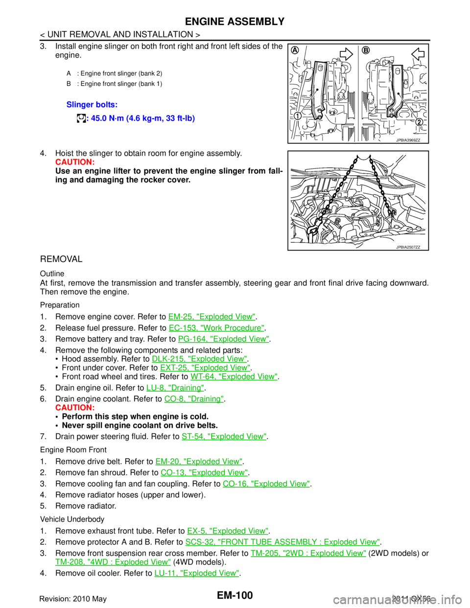
3. Install engine slinger on both front right and front left sides of theengine.
4. Hoist the slinger to obtain room for engine assembly. CAUTION:
Use an engine lifter to prevent the engine slinger from fall-
ing and damaging the rocker cover.
REMOVAL
Outline
At first, remove the transmission and transfer assemb ly, steering gear and front final drive facing downward.
Then remove the engine.
Preparation
1. Remove engine cover. Refer to EM-25, "Exploded View".
2. Release fuel pressure. Refer to EC-153, "
Work Procedure".
3. Remove battery and tray. Refer to PG-164, "
Exploded View".
4. Remove the following components and related parts: Hood assembly. Refer to DLK-215, "
Exploded View".
Front under cover. Refer to EXT-25, "
Exploded View".
Front road wheel and tires. Refer to WT-64, "
Exploded View".
5. Drain engine oil. Refer to LU-8, "
Draining".
6. Drain engine coolant. Refer to CO-8, "
Draining".
CAUTION:
Perform this step when engine is cold.
Never spill engine coolant on drive belts.
7. Drain power steering fluid. Refer to ST-54, "
Exploded View".
Engine Room Front
1. Remove drive belt. Refer to EM-20, "Exploded View".
2. Remove fan shroud. Refer to CO-13, "
Exploded View".
3. Remove cooling fan and fan coupling. Refer to CO-16, "
Exploded View".
4. Remove radiator hoses (upper and lower).
5. Remove radiator.
Vehicle Underbody
1. Remove exhaust front tube. Refer to EX-5, "Exploded View".
2. Remove protector A and B. Refer to SCS-32, "
FRONT TUBE ASSEMBLY : Exploded View".
3. Remove front suspension rear cross member. Refer to TM-205, "
2WD : Exploded View" (2WD models) or
TM-208, "
4WD : Exploded View" (4WD models).
4. Remove oil cooler. Refer to LU-11, "
Exploded View".
A : Engine front slinger (bank 2)
B : Engine front slinger (bank 1)
Slinger bolts:
: 45.0 N·m (4.6 kg-m, 33 ft-lb)
JPBIA3969ZZ
JPBIA2507ZZ
Revision: 2010 May2011 QX56
Page 2665 of 5598

ENGINE STAND SETTINGEM-103
< UNIT DISASSEMBLY AND ASSEMBLY >
C
DE
F
G H
I
J
K L
M A
EM
NP
O
UNIT DISASSEMBLY AND ASSEMBLY
ENGINE STAND SETTING
SettingINFOID:0000000006289579
NOTE:
Explained here is how to disassemble with engine stand s
upporting transmission surface. When using a differ-
ent type of engine stand, note the difference in the steps, etc.
1. Remove the engine assembly from the vehicle. Refer to EM-98, "
Exploded View".
2. Remove crankshaft pulley. Refer to EM-96, "
FRONT OIL SEAL : Removal and Installation".
NOTE:
The drive plate is fixed with a ring gear stopper [SST: KV10119200 (J-49277)]. Loosen the crankshaft pul-
ley mounting bolts before installing the engine stand.
3. Remove the parts that may restrict installation of engine to a widely used engine stand. Fix crankshaft with a ring gear stopper [SST: KV10119200 (J-49277)]. Loosen drive plate mounting bolt
with power tool.
Check for deformation or damage of drive plate. Refer to EM-115, "
Inspection".
NOTE:
The procedure is described assuming that you us e a widely used engine stand holding the surface, to
which transmission is installed.
4. Remove pilot converter using the pilot bushing puller (commercial service tool), if necessary.
5. Lift the engine with hoist to inst all it onto the widely used engine stand.
CAUTION:
Use an engine stand that has a load capacity [240 kg (529 lb) or more] large enough for supporting
the engine weight.
If the load capacity of the stand is not adequate, remove the following parts beforehand to reduce the potential risk of overturning the stand.
- Remove intake manifold. Refer to EM-30, "
Exploded View".
- Remove fuel injector and fuel tube assembly. Refer to EM-48, "
Exploded View".
- Remove ignition coil. Refer to EM-29, "
Exploded View".
- Remove rocker cover. Refer to EM-33, "
Exploded View".
- Remove exhaust manifold. Refer to EM-40, "
Exploded View".
- Other removable brackets. NOTE:
The figure shows an example of widely used engine stand (A)
that can hold mating surface of transmission with drive plate
removed.
CAUTION:
Before removing the hang ing chains, check the engine
stand is stable and there is no risk of overturning.
6. Drain engine oil. Refer to LU-8, "
Draining".
JPBIA0190ZZ
Revision: 2010 May2011 QX56
Page 3092 of 5598
HA-36
< REMOVAL AND INSTALLATION >
COOLER PIPE AND HOSE
9. Partly remove rear half of front fender protector RH. Refer to EXT-23, "FENDER PROTECTOR : Exploded
View".
10. Remove high-pressure pipe.
INSTALLATION
Note the following items, and install in the reverse order of removal.
CAUTION:
Replace O-rings with new ones. Then apply compressor oil to them when installing.
Check for leakages when recharging refrigerant. Refer to HA-18, "
Leak Test".
LOW-PRESSURE PIPE
LOW-PRESSURE PIPE : Removal and InstallationINFOID:0000000006276176
CAUTION:
Perform lubricant return operation before each re frigeration system disassembly. However, if a large
amount of refrigerant or lubrican t is detected, never perform lubricant return operation. Refer to HA-
22, "Perform Lubricant Return Operation".
REMOVAL
1. Use a refrigerant collecting equipment (for HF C-134a) to discharge the refrigerant. Refer to HA-22, "Per-
form Lubricant Return Operation".
2. Drain engine coolant from cooling system. Refer to CO-8, "
Draining".
3. Remove engine cover. Refer to EM-25, "
Removal and Installation".
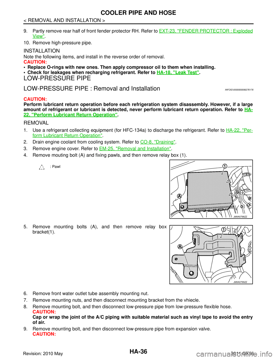
4. Remove mouting bolt (A) and fixing pawls, and then remove relay box (1).
5. Remove mounting bolts (A), and then remove relay box bracket(1).
6. Remove front water outlet tube assembly mounting nut.
7. Remove mounting nuts, and then disconnec t mounting bracket from the vhiecle.
8. Remove mounting bolt, and then disconnect low-pressure pipe from low-pressure flexible hose. CAUTION:
Cap or wrap the joint of the A/C piping with suitab le material such as vinyl tape to avoid the entry
of air.
9. Remove mounting bolt, and then disconnect low-pressure pipe from expansion valve. CAUTION:
: Pawl
JMIIA0798ZZ
JMIIA0799ZZ
Revision: 2010 May2011 QX56
Page 3099 of 5598
A/C UNIT ASSEMBLYHA-43
< REMOVAL AND INSTALLATION >
C
DE
F
G H
J
K L
M A
B
HA
N
O P
Perform lubricant return operati on before each refrigeration system disassembly. However, if a large
amount of refrigerant or lubricant is detected, n ever perform lubricant return operation. Refer to HA-
22, "Perform Lubricant Return Operation".
REMOVAL
1. Use a refrigerant collecting equipment (for HF C-134a) to discharge the refrigerant. Refer to HA-20, "Recy-
cle Refrigerant". (If equipped)
2. Drain engine coolant from cooling system. Refer to CO-8, "
Draining".
3. Remove clamps, and then disconnect front heater outlet hose from heater pipe.
CAUTION:
Some coolant may spill when heater hoses are disconnected.
Close off the coolant inlet and outlet on the heater core (2 locations) with shop cloths.
4. Remove mounting bolt, and then disconnect low-pressure pipe and high-pressure pipe from expansion valve.
CAUTION:
Cap or wrap the joint of the A/C piping and expan sion valve with suitable material such as vinyl
tape to avoid the entry of air.
5. Remove instrument panel assembly. Refer to IP-14, "
Removal and Installation".
6. Remove steering column mounting bolt and nuts. Refer to ST-34, "
Removal and Installation".
7. Move steering column assembly to a position where it does not inhibit work.
8. Disconnect harness clips, harness connectors, ground bol ts and blackets from steering member, and then
move the vehicle harness to the position without hindrance for work.
9. Remove mounting nuts, and then remove instrument stay (RH and LH).
10. Remove A/C unit assembly mounting bolts.
11. Remove mounting bolts, and then remove steering member from the vehicle.
12. Disconnect drain hose from A/C unit assembly, and then remove A/C unit assembly from the vehicle.
13. Remove mounting bolts, and then disconnect heater & cooling unit and blower unitassembly.
INSTALLATION
Note the following items, and install in the reverse order of removal.
CAUTION:
Replace O-rings with new ones. Then apply compressor oil to them when installing.
Check for leakages when recharging refrigerant. Refer to HA-18, "
Leak Test".
NOTE:
Refer to CO-9, "
Refilling" when filling radiator with engine coolant.
EVAPORATOR
EVAPORATOR : Removal and InstallationINFOID:0000000006276184
REMOVAL
1. Remove heater & cooling unit assembly. Refer to HA-41, "Exploded View".
2. Remove heater core. Refer to HA-44, "
HEATER CORE : Removal and Installation".
3. Remove mounting screws, and then remove evaporator pipe cover.
4. Remove air mix door motor (RH). Refer to HAC-153, "
AIR MIX DOOR MOTOR : Removal and Installa-
tion".
5. Remove mounting screws, and then remove A/C cover.
6. Remove foot duct LH. Refer to VTL-11, "
FLOOR DUCT 1 : Removal and Installation".
7. Remove mounting screws, and then remove A/C lower case.
8. Remove intake sensor. Refer to HAC-150, "
Removal and Installation".
9. Remove evaporator assembly from heater & cooling unit assembly.
10. Remove mounting bolts, and then remove evaporator from evaporator assembly.
CAUTION:
Cap or wrap the joint of the evaporator and evaporat or pipe assembly with suitable material such as
vinyl tape to avoid the entry of air.
Revision: 2010 May2011 QX56
Page 3103 of 5598

REAR A/C UNITHA-47
< REMOVAL AND INSTALLATION >
C
DE
F
G H
J
K L
M A
B
HA
N
O P
REAR A/C UNIT ASSEMBLY
REAR A/C UNIT ASSEMBLY : Removal and InstallationINFOID:0000000006276188
REMOVAL
1. Use a refrigerant collecting equipment (for HF C-134a) to discharge the refrigerant. Refer to HA-22, "Per-
form Lubricant Return Operation".
2. Drain engine coolant from cooling system. Refer to HA-22, "
Perform Lubricant Return Operation".
3. Remove rear ventilator duct upper. Refer to VTL-12, "
REAR VENTILATOR DUCT UPPER : Removal and
Installation".
4. Remove rear ventilator duct lower. Refer to VTL-12, "
REAR VENTILATOR DUCT LOWER : Removal and
Installation".
5. Remove mounting bolt, and then disconnect rear cooler unit pipe assembly from rear cooler pipe assem-
bly.
1. Rear blower harness 2. Rear blower motor 3. Rear A/C unit case RH
4. Rear evaporator pipe assembly 5. O-ring 6. Rear expantion valve assembly
7. Rear A/C cooler pipe assembly 8. Pipe bracket 9. Grommet
10. Rear cooler pipe 11. Rear heater outlet tube assembly 12. Blind cap
13. Rear heater inlet tube assembly 14. Clamp 15. Clamp
16. Shild plate 17. Bracket 18. Rear A/C unit case LH
19. Rear evapolator 20. Drain hose 21. Rear air mix door
22. Rear heater core 23. Rear heater pipe clamp 24. Rear A/C unit upper case (front)
25. Rear mode door 26. Rear A/C unit upper case (rear) 27. Air mix door harness
28. Rear intake sensor 29. Packing
Refer to GI-4, "
Components" for symbols in the figure.
JMIIA0641GB
Revision: 2010 May2011 QX56