Page 3375 of 5598
INT-26
< REMOVAL AND INSTALLATION >
FLOOR TRIM
10. Remove the following parts after removing the center console assembly. Remove ground bolt (G).
Disconnect floor harness connectors (A) and (E).
Disconnect yaw rate/side/decel G sensor harness connector (C). Refer to BRC-138, "
Exploded View".
Disconnect diagnosis sensor unit harness connector (D). Refer to SR-26, "
Exploded View".
Remove floor harness clamps (B) and (F).
11. Remove A/T shift selector assembly mounting bolts. Refer to TM-176, "
Removal and Installation".
12. Remove floor duct 1 (LH and RH). Refer to VTL-11, "
FLOOR DUCT 1 : Removal and Installation".
13. Disconnect drain hose (1) and remove instrument stay mounting nuts (A), and then remove instrument stay (2) (LH and RH).
14. Disengage front floor carpet from front floor carpet fixing clips (A).
JMJIA4226ZZ
JMJIA4225ZZ
JMJIA1560ZZ
Revision: 2010 May2011 QX56
Page 4246 of 5598
RF-32
< REMOVAL AND INSTALLATION >
GLASS LID
REMOVAL AND INSTALLATION
GLASS LID
Exploded ViewINFOID:0000000006141245
1. Glass lid 2. TORX bolt 3. Side trim
4. Rear drain connector 5. Rear drain hose 6. Sunroof bracket (LH,RH)
7. Front drain hose 8. Front drain connector 9. Sunroof motor assembly
10. Sunroof unit assembly
JMKIA5212ZZ
Revision: 2010 May2011 QX56
Page 4249 of 5598
SUNROOF MOTOR ASSEMBLYRF-35
< REMOVAL AND INSTALLATION >
C
DE
F
G H
I
J
L
M A
B
RF
N
O P
SUNROOF MOTOR ASSEMBLY
Exploded ViewINFOID:0000000006141248
1. Glass lid 2. TORX bolt 3. Side trim
4. Rear drain connector 5. Rear drain hose 6. Sunroof bracket (LH,RH)
7. Front drain hose 8. Front drain connector 9. Sunroof motor assembly
10. Sunroof unit assembly
JMKIA5212ZZ
Revision: 2010 May2011 QX56
Page 4251 of 5598
SUNROOF UNIT ASSEMBLYRF-37
< REMOVAL AND INSTALLATION >
C
DE
F
G H
I
J
L
M A
B
RF
N
O P
SUNROOF UNIT ASSEMBLY
Exploded ViewINFOID:0000000006141250
REMOVAL
DISASSEMBLY
1. Glass lid 2. TORX bolt 3. Side trim
4. Rear drain connector 5. Rear drain hose 6. Sunroof bracket (LH,RH)
7. Front drain hose 8. Front drain connector 9. Sunroof motor assembly
10. Sunroof unit assembly
JMKIA5212ZZ
Revision: 2010 May2011 QX56
Page 4253 of 5598

SUNROOF UNIT ASSEMBLYRF-39
< REMOVAL AND INSTALLATION >
C
DE
F
G H
I
J
L
M A
B
RF
N
O P
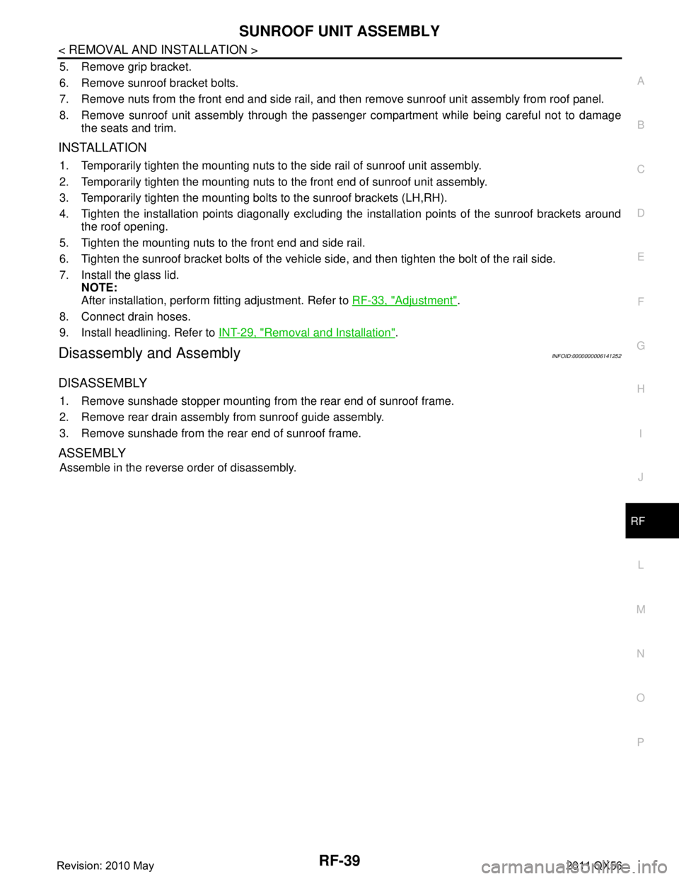
5. Remove grip bracket.
6. Remove sunroof bracket bolts.
7. Remove nuts from the front end and side rail, and then remove sunroof unit assembly from roof panel.
8. Remove sunroof unit assembly through the passenger compartment while being careful not to damage the seats and trim.
INSTALLATION
1. Temporarily tighten the mounting nuts to the side rail of sunroof unit assembly.
2. Temporarily tighten the mounting nuts to the front end of sunroof unit assembly.
3. Temporarily tighten the mounting bolts to the sunroof brackets (LH,RH).
4. Tighten the installation points diagonally excluding the installation points of the sunroof brackets around the roof opening.
5. Tighten the mounting nuts to the front end and side rail.
6. Tighten the sunroof bracket bolts of the vehicl e side, and then tighten the bolt of the rail side.
7. Install the glass lid. NOTE:
After installation, perform fitting adjustment. Refer to RF-33, "
Adjustment".
8. Connect drain hoses.
9. Install headlining. Refer to INT-29, "
Removal and Installation".
Disassembly and AssemblyINFOID:0000000006141252
DISASSEMBLY
1. Remove sunshade stopper mounting from the rear end of sunroof frame.
2. Remove rear drain assembly from sunroof guide assembly.
3. Remove sunshade from the rear end of sunroof frame.
ASSEMBLY
Assemble in the reverse order of disassembly.
Revision: 2010 May2011 QX56
Page 5030 of 5598

STEERING GEAR AND LINKAGEST-43
< REMOVAL AND INSTALLATION >
C
DE
F
H I
J
K L
M A
B
ST
N
O P
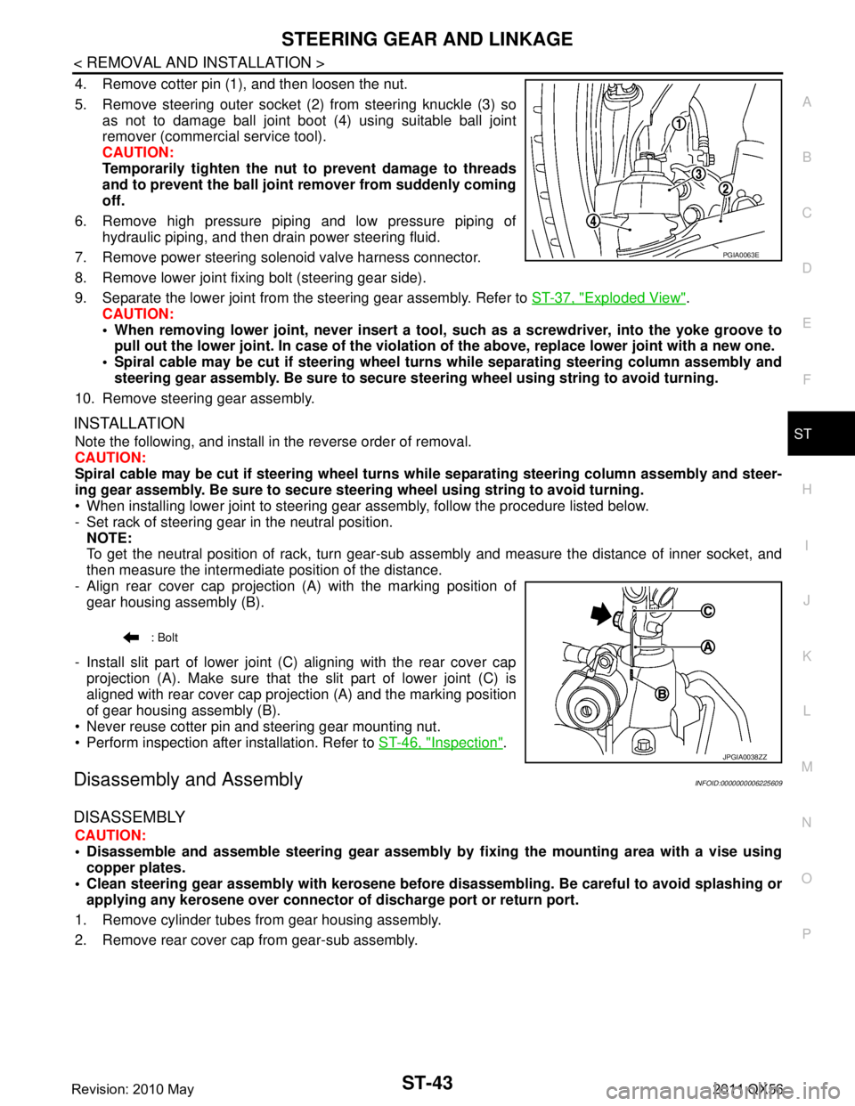
4. Remove cotter pin (1), and then loosen the nut.
5. Remove steering outer socket (2) from steering knuckle (3) so as not to damage ball joint boot (4) using suitable ball joint
remover (commercial service tool).
CAUTION:
Temporarily tighten the nut to prevent damage to threads
and to prevent the ball joint remover from suddenly coming
off.
6. Remove high pressure piping and low pressure piping of hydraulic piping, and then drain power steering fluid.
7. Remove power steering solenoid valve harness connector.
8. Remove lower joint fixing bolt (steering gear side).
9. Separate the lower joint from the steering gear assembly. Refer to ST-37, "
Exploded View".
CAUTION:
When removing lower joint, n ever insert a tool, such as a screw driver, into the yoke groove to
pull out the lower joint. In case of the violation of the above, replace lower joint with a new one.
Spiral cable may be cut if steering wheel tu rns while separating steering column assembly and
steering gear assembly. Be sure to secure st eering wheel using string to avoid turning.
10. Remove steering gear assembly.
INSTALLATION
Note the following, and install in the reverse order of removal.
CAUTION:
Spiral cable may be cut if steering wheel turns while separating steering column assembly and steer-
ing gear assembly. Be sure to secure steer ing wheel using string to avoid turning.
When installing lower joint to steering gear assembly, follow the procedure listed below.
- Set rack of steering gear in the neutral position.
NOTE:
To get the neutral position of rack, turn gear-sub a ssembly and measure the distance of inner socket, and
then measure the intermediat e position of the distance.
- Align rear cover cap projection (A) with the marking position of gear housing assembly (B).
- Install slit part of lower joint (C) aligning with the rear cover cap projection (A). Make sure that the slit part of lower joint (C) is
aligned with rear cover cap projection (A) and the marking position
of gear housing assembly (B).
Never reuse cotter pin and steering gear mounting nut.
Perform inspection after installation. Refer to ST-46, "
Inspection".
Disassembly and AssemblyINFOID:0000000006225609
DISASSEMBLY
CAUTION:
Disassemble and assemble steering gear assembly by fixing the mounting area with a vise using
copper plates.
Clean steering gear assembly with kerosene before disassembling. Be careful to avoid splashing or
applying any kerosene over connector of discharge port or return port.
1. Remove cylinder tubes from gear housing assembly.
2. Remove rear cover cap from gear-sub assembly.
PGIA0063E
: Bolt
JPGIA0038ZZ
Revision: 2010 May2011 QX56
Page 5036 of 5598

POWER STEERING OIL PUMPST-49
< REMOVAL AND INSTALLATION >
C
DE
F
H I
J
K L
M A
B
ST
N
O P
Removal and InstallationINFOID:0000000006225612
REMOVAL
1. Drain power steering fluid from reservoir tank. CAUTION:
Never reuse drained power steering fluid.
Always use the specified fluid. Refer to MA-10, "
Fluids and Lubricants".
2. Remove the reservoir tank. Refer to CO-13, "
Removal and Installation".
3. Remove the battery and battery tray from vehicle. Refer to PG-164, "
Removal and Installation".
4. Loosen drive belt. Refer to EM-20, "
Removal and Installation".
5. Remove drive belt from oil pump pulley.
6. Remove copper washers and eye bolt (drain fluid from their pipings).
7. Remove suction hose (drain fluid from their pipings).
8. Remove oil pump mounting bolts, and then remove oil pump.
INSTALLATION
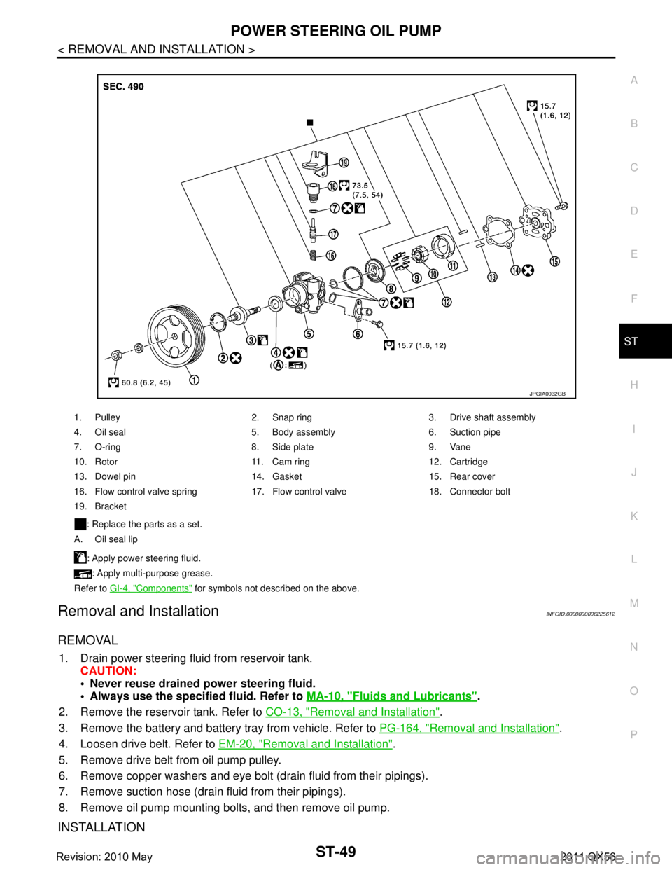
1. Pulley 2. Snap ring 3. Drive shaft assembly
4. Oil seal 5. Body assembly 6. Suction pipe
7. O-ring 8. Side plate 9. Vane
10. Rotor 11. Cam ring 12. Cartridge
13. Dowel pin 14. Gasket 15. Rear cover
16. Flow control valve spring 17. Flow control valve 18. Connector bolt
19. Bracket
: Replace the parts as a set.
A. Oil seal lip
: Apply power steering fluid.: Apply multi-purpose grease.
Refer to GI-4, "
Components" for symbols not described on the above.
JPGIA0032GB
Revision: 2010 May2011 QX56
Page 5185 of 5598
![INFINITI QX56 2011 Factory Service Manual
A/T FLUID COOLERTM-97
< BASIC INSPECTION > [7AT: RE7R01B]
C
EF
G H
I
J
K L
M A
B
TM
N
O P
A/T FLUID COOLER
CleaningINFOID:0000000006233276
Whenever an A/T is replaced, the A/ T fluid cooler mounted i INFINITI QX56 2011 Factory Service Manual
A/T FLUID COOLERTM-97
< BASIC INSPECTION > [7AT: RE7R01B]
C
EF
G H
I
J
K L
M A
B
TM
N
O P
A/T FLUID COOLER
CleaningINFOID:0000000006233276
Whenever an A/T is replaced, the A/ T fluid cooler mounted i](/manual-img/42/57033/w960_57033-5184.png)
A/T FLUID COOLERTM-97
< BASIC INSPECTION > [7AT: RE7R01B]
C
EF
G H
I
J
K L
M A
B
TM
N
O P
A/T FLUID COOLER
CleaningINFOID:0000000006233276
Whenever an A/T is replaced, the A/ T fluid cooler mounted in the radiator must be inspected and cleaned.
Metal debris and friction material, if present, can becom e trapped in the A/T fluid cooler. This debris can con-
taminate the newly serviced A/T or, in severe cases, can bl ock or restrict the flow of ATF. In either case, mal-
function of the newly se rviced A/T may result.
Debris, if present, may build up as ATF enters the cooler inlet. It will be necessary to back flush the cooler
through the cooler outlet in order to flush out any built up debris.
CLEANING PROCEDURE
1. Position an oil pan under the A/T inlet and outlet cooler hoses.
2. Identify the inlet and outlet fluid cooler hoses.
3. Disconnect the A/T fluid cooler inlet and outlet rubber hoses
from the steel cooler tubes or by-pass valve.
NOTE:
Replace the cooler hoses if rubber material from the hose
remains on the tube fitting.
4. Allow any ATF that remains in the cooler hoses to drain into the oil pan.
5. Insert the extension adapter hose of a can of Transmission Cooler Cleaner (Nissan P/N 999MP-AM006) into the cooler out-
let hose.
CAUTION:
Wear safety glasses and rubber gloves when spraying theTransmission Cooler Cleaner.
Spray Transmission Cooler Cleaner only with adequate
ventilation.
Avoid contact with eyes and skin.
Never breath vapors or spray mist.
6. Hold the hose and can as high as possible and spray Transmis- sion Cooler Cleaner in a continuous stream into the cooler outlet
hose until ATF flows out of the cooler inlet hose for 5 seconds.
7. Insert the tip of an air gun into the end of the cooler outlet hose.
8. Wrap a shop rag around the air gun tip and of the cooler outlet hose.
9. Blow compressed air regulated to 5 to 9 kg/cm
2 (71 to 128 psi)
through the cooler outlet hose for 10 seconds to force out any
remaining ATF.
10. Repeat steps 5 through 9 three additional times.
11. Position an oil pan under the banjo bolts that connect the A/T fluid cooler steel lines to the A/T.
12. Remove the banjo bolts.
13. Flush each steel line from the cooler side back toward the A/T by spraying Transmission Cooler Cleaner in a continuous stream for 5 seconds.
14. Blow compressed air regulated to 5 to 9 kg/cm
2 (71 to 128 psi) through each steel line from the cooler
side back toward the A/T for 10 seconds to force out any remaining ATF.
15. Ensure all debris is removed from the steel cooler lines.
16. Ensure all debris is removed from the banjo bolts and fittings.
17. Perform “DIAGNOSIS PROCEDURE”.
JPDIA0711GB
JPDIA0712GB
JPDIA0713GB
Revision: 2010 May2011 QX56