2011 INFINITI QX56 Back door
[x] Cancel search: Back doorPage 4630 of 5598
![INFINITI QX56 2011 Factory Service Manual
DIAGNOSIS SYSTEM (BCM)SEC-23
< SYSTEM DESCRIPTION > [WITH INTELLIGENT KEY SYSTEM]
C
D
E
F
G H
I
J
L
M A
B
SEC
N
O P
ENGINE START BY I-KEY Engine start function mode can be changed to operation with t INFINITI QX56 2011 Factory Service Manual
DIAGNOSIS SYSTEM (BCM)SEC-23
< SYSTEM DESCRIPTION > [WITH INTELLIGENT KEY SYSTEM]
C
D
E
F
G H
I
J
L
M A
B
SEC
N
O P
ENGINE START BY I-KEY Engine start function mode can be changed to operation with t](/manual-img/42/57033/w960_57033-4629.png)
DIAGNOSIS SYSTEM (BCM)SEC-23
< SYSTEM DESCRIPTION > [WITH INTELLIGENT KEY SYSTEM]
C
D
E
F
G H
I
J
L
M A
B
SEC
N
O P
ENGINE START BY I-KEY Engine start function mode can be changed to operation with this mode
On: Operate
Off: Non-operation
TRUNK/GLASS HATCH OPEN Buzzer reminder function mode by back door opener switch can be changed to operation with
this mode
On: Operate
Off: Non-operation
PANIC ALARM SET Panic alarm button pressing time on Intelligent Key button can be selected from the following
with this mode
MODE 1: 0.5 sec
MODE 2: Non-operation
MODE 3: 1.5 sec
TRUNK OPEN DELAY Back door open button pressing to Intelligent Key button can be selected as per the following
in this mode
MODE 1: Press and hold
MODE 2: Press twice
MODE 3: Press and hold, or press twice
LO- BATT OF KEY FOB WARN Intelligent Key low battery warning mode can be changed to operation with this mode
On: Operate
Off: Non-operation
ANTI KEY LOCK IN FUNCTI Key reminder function mode can be changed to operation with this mode
On: Operate
Off: Non-operation
HAZARD ANSWER BACK Hazard reminder function mode by door request switch and Intelligent Key button can be se-
lected from the following with this mode
Lock Only: Door lock operation only
Unlock Only: Door unlock operation only
Lock/Unlock: Lock and unlock operation
Off: Non-operation
ANS BACK I-KEY LOCK Buzzer reminder function (lock operation) mode by door request switch can be selected from
the following with this mode
Horn Chirp: Sound horn
Buzzer: Sound Intelligent Key warning buzzer
Off: Non-operation
ANS BACK I-KEY UNLOCK Buzzer reminder function (unlock operation) mode by door request switch can be changed to
operation with this mode
On: Operate
Off: Non-operation
SHORT CRANKING OUTPUT Starter motor can operate during the times below
70 msec
100 msec
200 msec
CONFIRM KEY FOB ID It can be checked wh ether Intelligent Key ID code is registered or not in this mode
AUTO LOCK SET Auto door lock operation time can be changed in this mode
MODE 1: OFF
MODE 2: 30 sec
MODE 3: 1 minute
MODE 4: 2 minutes
MODE 5: 3 minutes
MODE 6: 4 minutes
MODE 7: 5 minutes
HORN WITH KEYLESS LOCK Horn reminder function mode by Intelligent Key button can be selected from the following with
this mode
On: Operate
Off: Non-operation
Monitor item Description
Revision: 2010 May2011 QX56
Page 4631 of 5598
![INFINITI QX56 2011 Factory Service Manual
SEC-24
< SYSTEM DESCRIPTION >[WITH INTELLIGENT KEY SYSTEM]
DIAGNOSIS SYSTEM (BCM)
SELF-DIAG RESULT
Refer to
BCS-57, "DTCIndex".
DATA MONITOR
PW DOWN SET Unlock button pressing time on Intelligent Ke INFINITI QX56 2011 Factory Service Manual
SEC-24
< SYSTEM DESCRIPTION >[WITH INTELLIGENT KEY SYSTEM]
DIAGNOSIS SYSTEM (BCM)
SELF-DIAG RESULT
Refer to
BCS-57, "DTCIndex".
DATA MONITOR
PW DOWN SET Unlock button pressing time on Intelligent Ke](/manual-img/42/57033/w960_57033-4630.png)
SEC-24
< SYSTEM DESCRIPTION >[WITH INTELLIGENT KEY SYSTEM]
DIAGNOSIS SYSTEM (BCM)
SELF-DIAG RESULT
Refer to
BCS-57, "DTCIndex".
DATA MONITOR
PW DOWN SET Unlock button pressing time on Intelligent Key button can be selected from the following with
this mode
MODE 1: 3 sec
MODE 2: Non-operation
MODE 3: 5 sec
WELCOME LIGHT SELECT Welcome light function mode can be selected from the following with this mode
Puddle/Outside Handle
Room lamp
Head & Tail Lamps (this item is displayed, but cannot be used)
Heart Beat
WELCOME LIGHT OP SET Welcome light function mode can be changed to operation with this mode
On: Operate
Off: Non-operation
Monitor item Description
Monitor Item Condition
REQ SW -DR Indicates [On/Off] condition of door request switch (driver side)
REQ SW -AS Indicates [On/Off] condition of door request switch (passenger side)
REQ SW -BD/TR Indicates [On/Off] condition of back door request switch
PUSH SW Indicates [On/Off] condition of push-button ignition switch
CLUTCH SW NOTE:
This item is displayed, but cannot be monitored
BRAKE SW 1 Indicates [On/Off]* condition of stop lamp switch power supply
BRAKE SW 2 Indicates [On/Off] condition of stop lamp switch
DETE/CANCL SW Indicates [On/Off] condition of P position
SFT PN/N SW Indicates [On/Off] condition of P or N position
S/L -LOCK Indicates [On/Off] condition of steering lock unit (LOCK)
S/L -UNLOCK Indicates [On/Off] condition of steering lock unit (UNLOCK)
S/L RELAY -F/B Indicates [On/Off] condition of steering lock relay
UNLK SEN -DR Indicates [On/Off] condition of driver door UNLOCK status
PUSH SW -IPDM Indicates [On/Off] condition of push-button ignition switch
IGN RLY1 -F/B Indicates [On/Off] condition of ignition relay 1
DETE SW -IPDM Indicates [On/Off] condition of P position
SFT PN -IPDM Indicates [On/Off] condition of P or N position
SFT P -MET Indicates [On/Off] condition of P position
SFT N -MET Indicates [On/Off] condition of N position
ENGINE STATE Indicates [Stop/Stall/Crank/Run] condition of engine states
S/L LOCK-IPDM Indicates [On/Off] condition of steering lock unit (LOCK)
S/L UNLK-IPDM Indicates [On/Off] condition of steering lock unit (UNLOCK)
S/L RELAY-REQ Indicates [On/Off] condition of steering lock relay
VEH SPEED 1 Display the vehicle speed signal received from combination meter by numerical value [Km/h]
VEH SPEED 2 Display the vehi cle speed signal received from ABS or VDC or TCM by numerical value [Km/h]
DOOR STAT-DR Indicates [LOCK/READY/UNLK] condition of unlock sensor
DOOR STAT-AS Indicates [LOCK/READY/UNLK] condition of passenger side door status
ID OK FLAG Indicates [Set/Reset] condition of key ID
PRMT ENG STRT Indicates [Set/Reset] condition of engine start possibility
Revision: 2010 May2011 QX56
Page 4633 of 5598
![INFINITI QX56 2011 Factory Service Manual
SEC-26
< SYSTEM DESCRIPTION >[WITH INTELLIGENT KEY SYSTEM]
DIAGNOSIS SYSTEM (BCM)
THEFT ALM
THEFT ALM : CONSULT-III Function (BCM - THEFT)INFOID:0000000006226189
DATA MONITOR
WORK SUPPORT
LOCK INDICA INFINITI QX56 2011 Factory Service Manual
SEC-26
< SYSTEM DESCRIPTION >[WITH INTELLIGENT KEY SYSTEM]
DIAGNOSIS SYSTEM (BCM)
THEFT ALM
THEFT ALM : CONSULT-III Function (BCM - THEFT)INFOID:0000000006226189
DATA MONITOR
WORK SUPPORT
LOCK INDICA](/manual-img/42/57033/w960_57033-4632.png)
SEC-26
< SYSTEM DESCRIPTION >[WITH INTELLIGENT KEY SYSTEM]
DIAGNOSIS SYSTEM (BCM)
THEFT ALM
THEFT ALM : CONSULT-III Function (BCM - THEFT)INFOID:0000000006226189
DATA MONITOR
WORK SUPPORT
LOCK INDICATORThis test is able to check LOCK indicato
r (push-button ignition switch) operation
On: Operate
Off: Non-operation
ACC INDICATOR This test is able to check ACC indicator (push-button ignition switch) operation
On: Operate
Off: Non-operation
IGNITION ON IND This test is able to check ON indicator (push-button ignition switch) operation
On: Operate
Off: Non-operation
HORN This test is able to check horn operation
On: Operate
Off: Non-operation
TRUNK/BACK DOOR NOTE:
This item is displayed, but cannot be used
Test item Description
Monitored Item Description
REQ SW -DR Indicates [ON/OFF] condition of door request switch (driver side).
REQ SW -AS Indicates [ON/OFF] condition of door request switch (passenger side).
REQ SW -RR NOTE:
This item is displayed, but cannot be monitored.
REQ SW -RL NOTE:
This item is displayed, but cannot be monitored.
REQ SW -BD/TR Indicates [ON/OFF] condition of back door request switch.
PUSH SW Indicates [ON/OFF] condition of push-button ignition switch
UNLK SEN -DR Indicates [ON/OFF] condition of driver door UNLOCK status.
DOOR SW-DR Indicates [ON/OFF] condition of front door switch (driver side).
DOOR SW-AS Indicates [ON/OFF] condition of front door switch (passenger side).
DOOR SW-RR Indicates [ON/OFF] condition of rear door switch RH.
DOOR SW-RL Indicates [ON/OFF] condition of rear door switch LH.
DOOR SW-BK Indicates [ON/OFF] condition of back door switch.
CDL LOCK SW Indicates [ON/OFF] condition of lock signal from door lock/unlock switch LH and RH.
CDL UNLOCK SW Indicates [ON/OFF] condition of unlock signal from door lock/unlock switch LH and RH.
KEY CYL LK-SW Indicates [ON/OFF] condition of lock signal from door key cylinder.
KEY CYL UN-SW Indicates [ON/OFF] condition of unlock signal from door key cylinder.
TR/BD OPEN SW Indicates [ON/OFF] condition of back door opener switch.
TRNK/HAT MNTR NOTE:
This item is displayed, but cannot be monitored.
RKE-LOCK Indicates [ON/OFF] condition of LOCK signal from Intelligent Key.
RKE-UNLOCK Indicates [ON/OFF] condition of UNLOCK signal from Intelligent Key.
RKE-TR/BD NOTE:
This item is displayed, but cannot be monitored.
Revision: 2010 May2011 QX56
Page 4770 of 5598

COLLISION DIAGNOSISSR-7
< BASIC INSPECTION >
C
DE
F
G
I
J
K L
M A
B
SR
N
O P
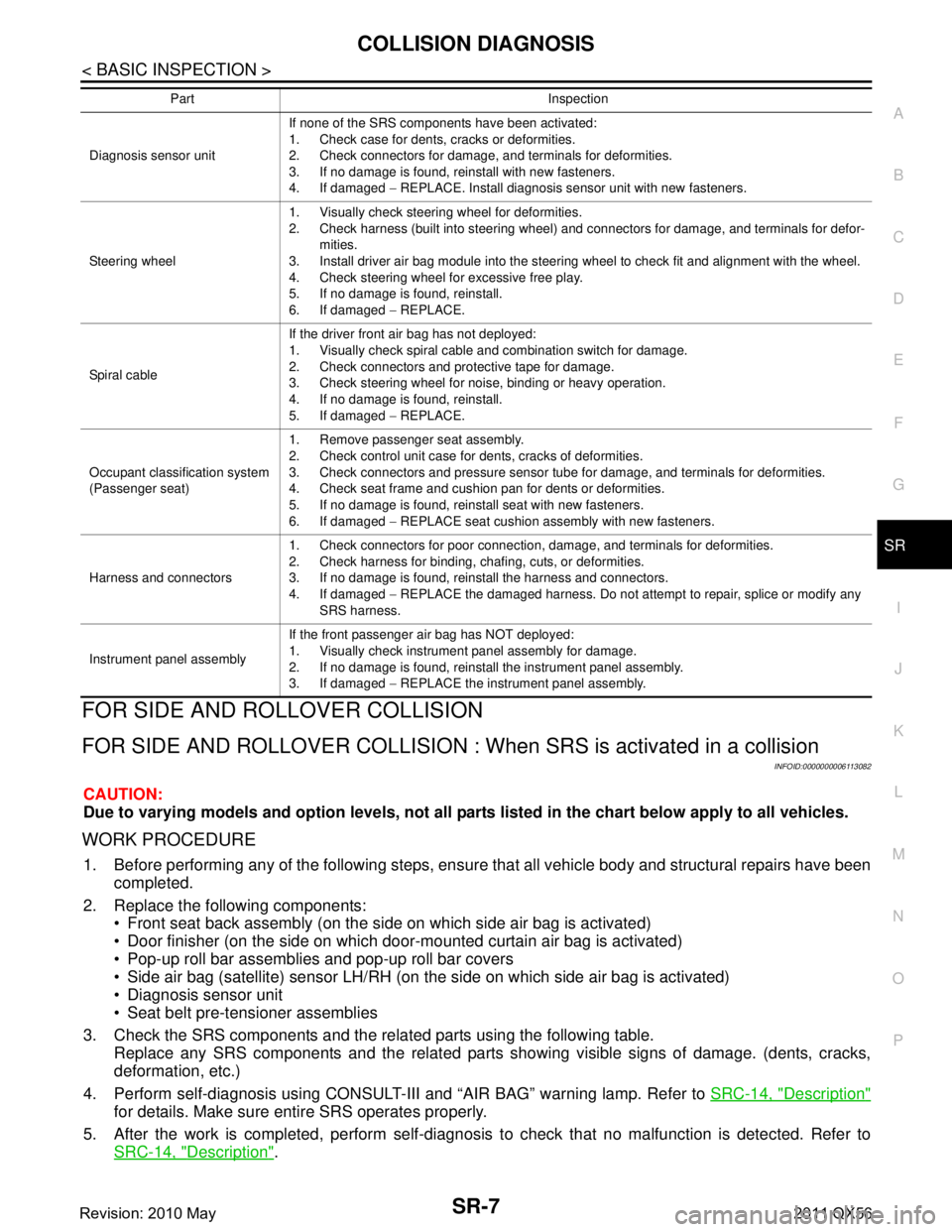
FOR SIDE AND ROLLOVER COLLISION
FOR SIDE AND ROLLOVER CO LLISION : When SRS is activated in a collision
INFOID:0000000006113082
CAUTION:
Due to varying models and option levels, not all parts listed in the chart below apply to all vehicles.
WORK PROCEDURE
1. Before performing any of the following steps, ensur e that all vehicle body and structural repairs have been
completed.
2. Replace the following components: Front seat back assembly (on the side on which side air bag is activated)
Door finisher (on the side on which door-mounted curtain air bag is activated)
Pop-up roll bar assemblies and pop-up roll bar covers
Side air bag (satellite) sensor LH/RH (on the side on which side air bag is activated)
Diagnosis sensor unit
Seat belt pre-tensioner assemblies
3. Check the SRS components and the related parts using the following table. Replace any SRS components and the related parts s howing visible signs of damage. (dents, cracks,
deformation, etc.)
4. Perform self-diagnosis using CONSULT-III and “AIR BAG” warning lamp. Refer to SRC-14, "
Description"
for details. Make sure entire SRS operates properly.
5. After the work is completed, perform self-diagnosis to check that no malfunction is detected. Refer to
SRC-14, "
Description".
Diagnosis sensor unit If none of the SRS components have been activated:
1. Check case for dents, cracks or deformities.
2. Check connectors for damage, and terminals for deformities.
3. If no damage is found, reinstall with new fasteners.
4. If damaged
− REPLACE. Install diagnosis sensor unit with new fasteners.
Steering wheel 1. Visually check steering wheel for deformities.
2. Check harness (built into steering wheel) and connectors for damage, and terminals for defor-
mities.
3. Install driver air bag module into the steering wheel to check fit and alignment with the wheel.
4. Check steering wheel for excessive free play.
5. If no damage is found, reinstall.
6. If damaged − REPLACE.
Spiral cable If the driver front air bag has not deployed:
1. Visually check spiral cable and combination switch for damage.
2. Check connectors and protective tape for damage.
3. Check steering wheel for noise, binding or heavy operation.
4. If no damage is found, reinstall.
5. If damaged
− REPLACE.
Occupant classification system
(Passenger seat) 1. Remove passenger seat assembly.
2. Check control unit case for dents, cracks of deformities.
3. Check connectors and pressure sensor tube for damage, and terminals for deformities.
4. Check seat frame and cushion pan for dents or deformities.
5. If no damage is found, reinstall seat with new fasteners.
6. If damaged
− REPLACE seat cushion assembly with new fasteners.
Harness and connectors 1. Check connectors for poor connection, damage, and terminals for deformities.
2. Check harness for binding, chafing, cuts, or deformities.
3. If no damage is found, reinstall the harness and connectors.
4. If damaged
− REPLACE the damaged harness. Do not attempt to repair, splice or modify any
SRS harness.
Instrument panel assembly If the front passenger air bag has NOT deployed:
1. Visually check instrument panel assembly for damage.
2. If no damage is found, reinstall the instrument panel assembly.
3. If damaged
− REPLACE the instrument panel assembly.
Part Inspection
Revision: 2010 May2011 QX56
Page 4771 of 5598

SR-8
< BASIC INSPECTION >
COLLISION DIAGNOSIS
SRS INSPECTION (FOR SIDE AND ROLLOVER COLLISION)
FOR SIDE AND ROLLOVER COLLISION : When SRS is not activated in a collision
INFOID:0000000006113083
CAUTION:
Due to varying models and option levels, not all part s listed in the chart below apply to all vehicles.
WORK PROCEDURE
1. Before performing any of the following steps, ensur e that all vehicle body and structural repairs have been
completed.
2. Check the SRS components and the related parts using the following table. If the front seat back assembly is damaged, t he front seat back assembly must be replaced.
If the door finisher assembly is damaged, the door finisher assembly and door-mounted curtain air bag
module must be replaced.
3. Perform self-diagnosis using CONSULT-III and “AIR BAG” warning lamp. Refer to SRC-14, "
Description"
for details. Make sure entire SRS operates properly.
4. After the work is completed, perform self-diagnosis to check that no malfunction is detected. Refer to
SRC-14, "
Description".
SRS INSPECTION (FOR SIDE AND ROLLOVER COLLISION)
Part Inspection
Side curtain air bag module LH If the side curtain air bag LH has deployed:
REPLACE the side curtain air bag module LH.
Install with new fasteners.
Side curtain air bag module RH If the side curtain air bag RH has deployed:
REPLACE the side curtain air bag module RH.
Install with new fasteners.
Front side air bag module LH If the front side air bag LH has deployed:
REPLACE front seatback assembly LH.
Front side air bag module RH If the front side air bag RH has deployed:
REPLACE front seatback assembly RH.
Side air bag (satellite) sensor
(LH or RH) If any of the SRS components have deployed:
REPLACE the side air bag (satellite) sensor on the collision side with new fasteners.
Diagnosis sensor unit If any of the SRS components have deployed:
REPLACE the diagnosis sensor unit with new fasteners.
Seat belt pre-tensioner assem-
blies
(All applicable locations: buckle,
retractor, lap outer) If either the driver or passenger seat belt pre-tensioner* has been activated:
REPLACE all seat belt pre-tensioner assemblies with new fasteners.
*: Confirm seat belt pre-tensioner activation using CONSULT-III only.
Center inner pillar 1. Check the center inner pillar on the collision side for damage (dents, cracks, deformation, etc.).
2. If damaged
− REPAIR the center inner pillar.
Trim/headlining 1. Check for visible signs of damage (dents, cracks, deformation, etc.) of the interior trim on the
collision side.
2. If damaged − REPLACE the damaged trim parts.
Door-mounted curtain air bag
module LH If the door-mounted curtain air bag module LH has deployed:
REPLACE the door finisher LH and door-mounted curtain air bag module.
Install with new fasteners.
Door-mounted curtain air bag
module RH If the door-mounted curtain air bag module RH has deployed:
REPLACE the door finisher RH and door-mounted curtain air bag module.
Install with new fasteners.
Pop-up roll bar assemblies If the pop-up roll bar has deployed:
REPLACE pop-up roll bar assemblies and pop-up roll bar covers.
Install with new fasteners.
Revision: 2010 May2011 QX56
Page 4773 of 5598

SR-10
< BASIC INSPECTION >
COLLISION DIAGNOSIS
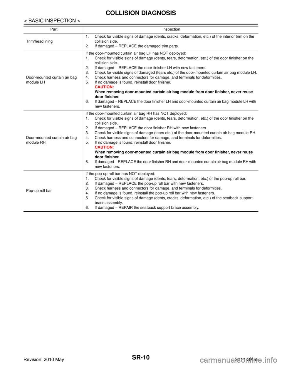
Trim/headlining1. Check for visible signs of damage (dents, cracks, deformation, etc.) of the interior trim on the
collision side.
2. If damaged − REPLACE the damaged trim parts.
Door-mounted curtain air bag
module LH If the door-mounted curtain air bag LH has NOT deployed:
1. Check for visible signs of damage (dents, tears, deformation, etc.) of the door finisher on the
collision side.
2. If damaged − REPLACE the door finisher LH with new fasteners.
3. Check for visible signs of damaged (tears etc.) of the door-mounted curtain air bag module LH.
4. Check harness and connectors for damage, and terminals for deformities.
5. If no damage is found, reinstall door finisher. CAUTION:
When removing door-mounted curtain air bag module from door finisher, never reuse
door finisher.
6. If damaged − REPLACE the door finisher LH and door-mounted curtain air bag module LH with
new fasteners.
Door-mounted curtain air bag
module RH If the door-mounted curtain air bag RH has NOT deployed:
1. Check for visible signs of damage (dents, tears, deformation, etc.) of the door finisher on the
collision side.
2. If damaged − REPLACE the door finisher RH with new fasteners.
3. Check for visible signs of damage (tears etc.) of the door-mounted curtain air bag module RH.
4. Check harness and connectors for damage, and terminals for deformities.
5. If no damage is found, reinstall door finisher. CAUTION:
When removing door-mounted curtain air bag module from door finisher, never reuse
door finisher.
6. If damaged − REPLACE the door finisher RH and door-mounted curtain air bag module RH with
new fasteners.
Pop-up roll bar If the pop-up roll bar has NOT deployed:
1. Check for visible signs of damage (dents, tears, deformation, etc.) of the pop-up roll bar.
2. If damaged
− REPLACE the pop-up roll bar with new fasteners.
3. Check harness and connectors for damage, and terminals for deformities.
4. If no damage is found, reinstall the pop-up roll bar with new fasteners.
5. Check for visible signs of damage (dents, cracks, deformation, etc.) of the seatback support brace assembly.
6. If damaged − REPAIR the seatback support brace assembly.
Part Inspection
Revision: 2010 May2011 QX56
Page 4969 of 5598

SRC-176
< DTC/CIRCUIT DIAGNOSIS >
B1211 ROLLOVER DETECTION
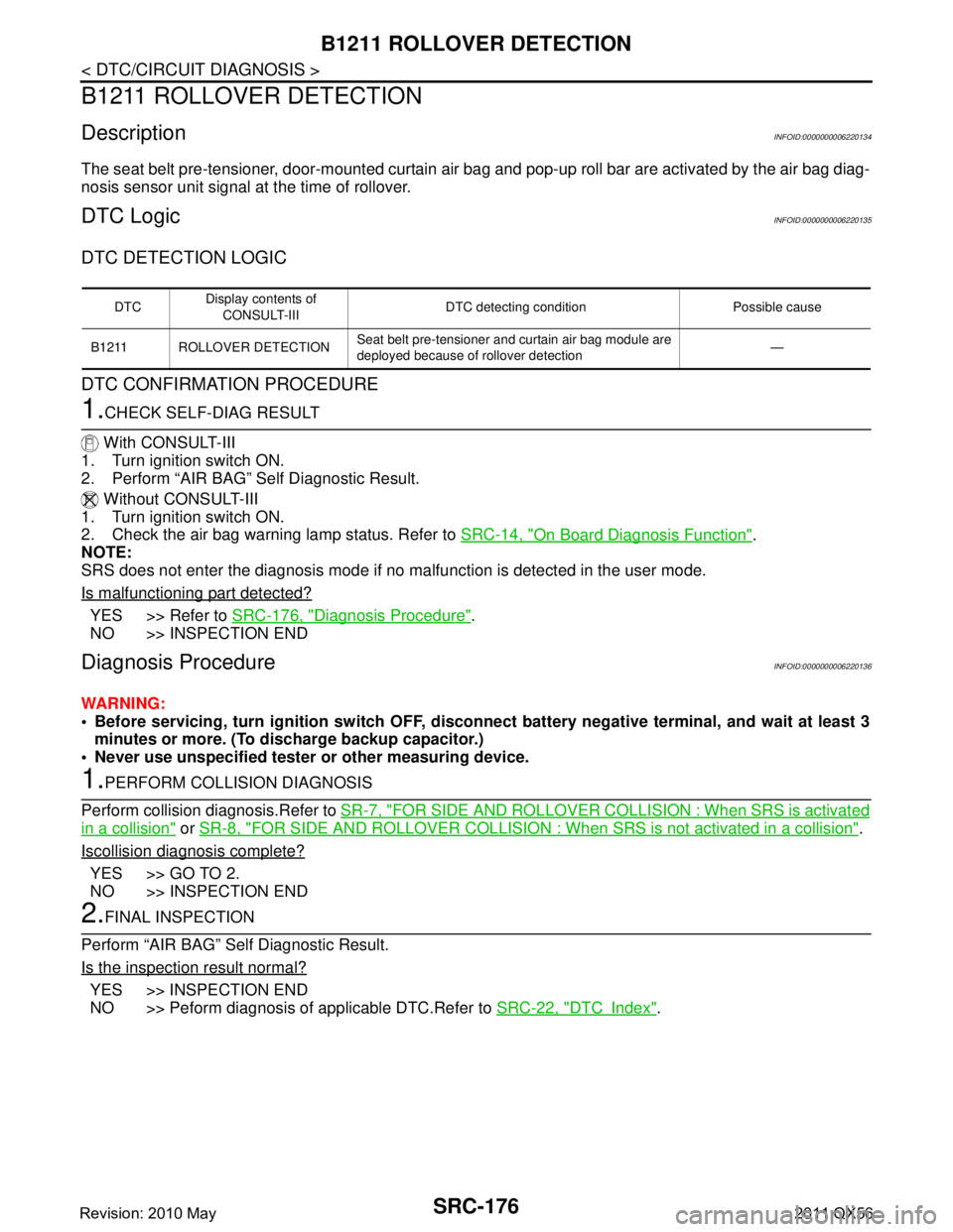
B1211 ROLLOVER DETECTION
DescriptionINFOID:0000000006220134
The seat belt pre-tensioner, door-mounted curtain air bag and pop-up roll bar are activated by the air bag diag-
nosis sensor unit signal at the time of rollover.
DTC LogicINFOID:0000000006220135
DTC DETECTION LOGIC
DTC CONFIRMATION PROCEDURE
1.CHECK SELF-DIAG RESULT
With CONSULT-III
1. Turn ignition switch ON.
2. Perform “AIR BAG” Self Diagnostic Result.
Without CONSULT-III
1. Turn ignition switch ON.
2. Check the air bag warning lamp status. Refer to SRC-14, "
On Board Diagnosis Function".
NOTE:
SRS does not enter the diagnosis mode if no malfunction is detected in the user mode.
Is malfunctioning part detected?
YES >> Refer to SRC-176, "Diagnosis Procedure".
NO >> INSPECTION END
Diagnosis ProcedureINFOID:0000000006220136
WARNING:
Before servicing, turn ignition sw itch OFF, disconnect battery negative terminal, and wait at least 3
minutes or more. (To discharge backup capacitor.)
Never use unspecified tester or other measuring device.
1.PERFORM COLLISION DIAGNOSIS
Perform collision diagnosis.Refer to SR-7, "
FOR SIDE AND ROLLOVER COLLISI ON : When SRS is activated
in a collision" or SR-8, "FOR SIDE AND ROLLOVER COLLISION : When SRS is not activated in a collision".
Iscollision diagnosis complete?
YES >> GO TO 2.
NO >> INSPECTION END
2.FINAL INSPECTION
Perform “AIR BAG” Self Diagnostic Result.
Is the inspection result normal?
YES >> INSPECTION END
NO >> Peform diagnosis of applicable DTC.Refer to SRC-22, "
DTCIndex".
DTCDisplay contents of
CONSULT-III DTC detecting condition Possible cause
B1211 ROLLOVER DETECTION Seat belt pre-tensioner and curtain air bag module are
deployed because of rollover detection —
Revision: 2010 May2011 QX56
Page 5423 of 5598

WCS
DIAGNOSIS SYSTEM (BCM)WCS-19
< SYSTEM DESCRIPTION >
C
DE
F
G H
I
J
K L
M B A
O P
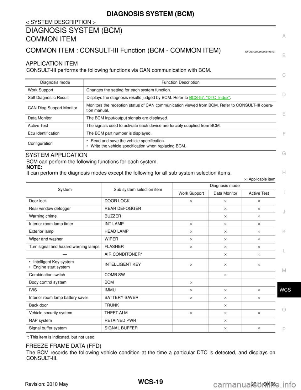
DIAGNOSIS SYSTEM (BCM)
COMMON ITEM
COMMON ITEM : CONSULT-III Fu nction (BCM - COMMON ITEM)INFOID:0000000006419721
APPLICATION ITEM
CONSULT-III performs the following functions via CAN communication with BCM.
SYSTEM APPLICATION
BCM can perform the following functions for each system.
NOTE:
It can perform the diagnosis modes except the following for all sub system selection items.
×: Applicable item
*: This item is indicated, but not used.
FREEZE FRAME DATA (FFD)
The BCM records the following vehicle condition at the time a particular DTC is detected, and displays on
CONSULT-III.
Diagnosis mode Function Description
Work Support Changes the setting for each system function.
Self Diagnostic Result Displays the diagnosis results judged by BCM. Refer to BCS-57, "
DTCIndex".
CAN Diag Support Monitor Monitors the reception status of CAN communication viewed from BCM. Refer to CONSULT-III opera-
tion manual.
Data Monitor The BCM input/output signals are displayed.
Active Test The signals used to activate each device are forcibly supplied from BCM.
Ecu Identification The BCM part number is displayed.
Configuration Read and save the vehicle specification.
Write the vehicle specification when replacing BCM.
System Sub system selection item Diagnosis mode
Work Support Data Monitor Active Test
Door lock DOOR LOCK ×××
Rear window defo gger REAR DEFOGGER ××
Warning chime BUZZER ××
Interior room lamp timer INT LAMP ×××
Exterior lamp HEAD LAMP ×××
Wiper and washer WIPER ×××
Turn signal and hazard warning lamps FLASHER ×××
— AIR CONDITONER* ××
Intelligent Key system
Engine start system INTELLIGENT KEY
×××
Combination switch COMB SW ×
Body control system BCM ×
IVIS IMMU ×××
Interior room lamp battery saver BATTERY SAVER ×××
Back door TRUNK ×
Vehicle security system THEFT ALM ×××
RAP system RETAINED PWR ×
Signal buffer system SIGNAL BUFFER ××
Revision: 2010 May2011 QX56