Page 2872 of 5598

REAR BUMPEREXT-17
< REMOVAL AND INSTALLATION >
C
DE
F
G H
I
J
L
M A
B
EXT
N
O P
Removal and InstallationINFOID:0000000006367600
REMOVAL
CAUTION:
Bumper fascia is made of resin. Never apply strong force to it, and be careful to prevent contact with
oil.
1. Fully open back door assembly.
2. Remove rear combination lamp (LH and RH). Refer to EXL-138, "
Removal and Installation".
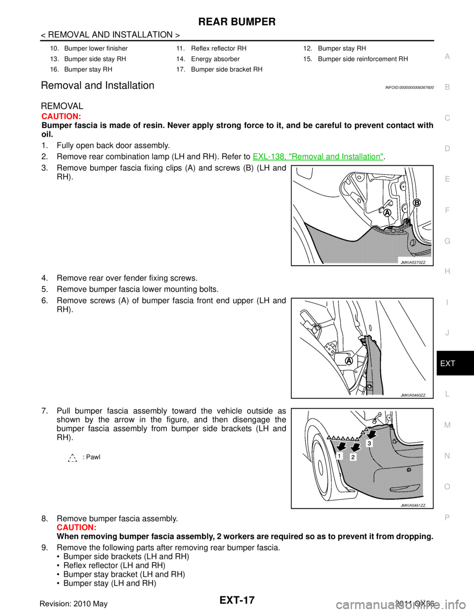
3. Remove bumper fascia fixing clips (A) and screws (B) (LH and RH).
4. Remove rear over fender fixing screws.
5. Remove bumper fascia lower mounting bolts.
6. Remove screws (A) of bumper fascia front end upper (LH and RH).
7. Pull bumper fascia assembly toward the vehicle outside as shown by the arrow in the figure, and then disengage the
bumper fascia assembly from bumper side brackets (LH and
RH).
8. Remove bumper fascia assembly. CAUTION:
When removing bumper fascia assembly, 2 workers ar e required so as to prevent it from dropping.
9. Remove the following parts after removing rear bumper fascia. Bumper side brackets (LH and RH)
Reflex reflector (LH and RH)
Bumper stay bracket (LH and RH)
Bumper stay (LH and RH)
10. Bumper lower finisher 11. Reflex reflector RH 12. Bumper stay RH
13. Bumper side stay RH 14. Energy absorber 15. Bumper side reinforcement RH
16. Bumper stay RH 17. Bumper side bracket RH
JMKIA5370ZZ
JMKIA5460ZZ
: Pawl
JMKIA5461ZZ
Revision: 2010 May2011 QX56
Page 2873 of 5598
EXT-18
< REMOVAL AND INSTALLATION >
REAR BUMPER
Bumper protector (LH and RH)
Bumper side reinforcement (LH and RH)
10. Remove energy absorber.
INSTALLATION
Note the following item, and then install in the reverse order of removal.
NOTE:
The following table shows the specified values for checking normal installation status.
Fitting adjustment cannot be performed.
JMKIA5455ZZ
Portion Clearance Surface height difference
Bumper fascia assembly –
Rear fender A – A0.0 – 1.0 mm
(0.000 – 0.039 in) (-0.7) – (+1.3) mm
[(-0.028) – (+0.051) in]
Bumper fascia assembly –
Rear combination lamp B – B0.3 – 3.0 mm
(0.012 – 0.118 in) —
Bumper fascia assembly –
Back door C – C2.8 – 6.1 mm
(0.110 – 0.240 in) —
Bumper fascia assembly –
Back door D – D3.8 – 7.8 mm
(0.150 – 0.307 in) —
Revision: 2010 May2011 QX56
Page 2893 of 5598

EXT-38
< REMOVAL AND INSTALLATION >
DOOR SASH COVER
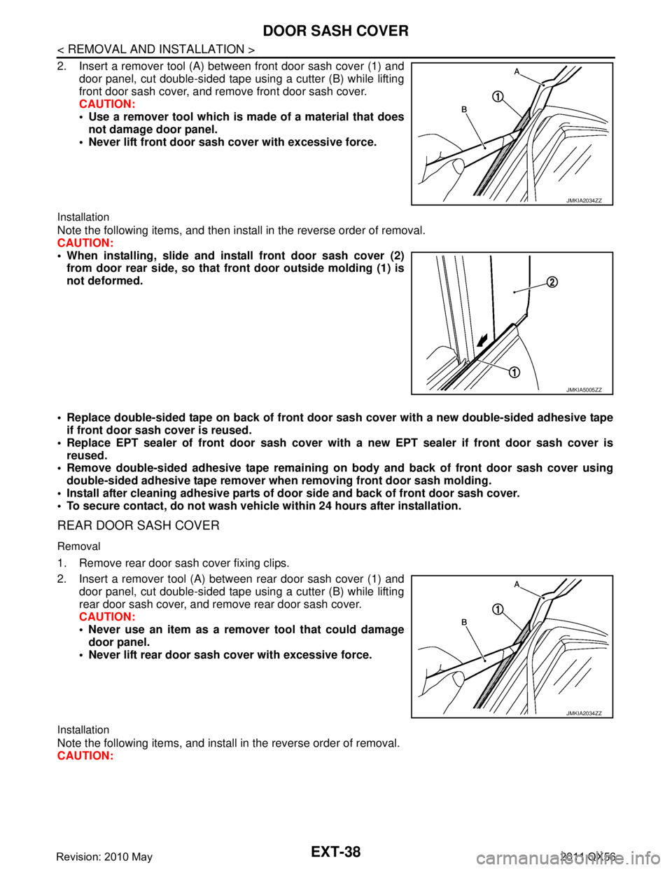
2. Insert a remover tool (A) between front door sash cover (1) anddoor panel, cut double-sided tape using a cutter (B) while lifting
front door sash cover, and remove front door sash cover.
CAUTION:
Use a remover tool which is made of a material that doesnot damage door panel.
Never lift front door sash cover with excessive force.
Installation
Note the following items, and then install in the reverse order of removal.
CAUTION:
When installing, slid e and install front door sash cover (2)
from door rear side, so that front door outside molding (1) is
not deformed.
Replace double-sided tape on back of front door sash cover with a new double-sided adhesive tape
if front door sash cover is reused.
Replace EPT sealer of front door sash cover with a new EPT sealer if front door sash cover is
reused.
Remove double-sided adhesive ta pe remaining on body and back of front door sash cover using
double-sided adhesive tape remover wh en removing front door sash molding.
Install after cleaning adhesive parts of doo r side and back of front door sash cover.
To secure contact, do not wash vehicle within 24 hours after installation.
REAR DOOR SASH COVER
Removal
1. Remove rear door sash cover fixing clips.
2. Insert a remover tool (A) between rear door sash cover (1) and
door panel, cut double-sided tape using a cutter (B) while lifting
rear door sash cover, and remove rear door sash cover.
CAUTION:
Never use an item as a remover tool that could damagedoor panel.
Never lift rear door sash cover with excessive force.
Installation
Note the following items, and install in the reverse order of removal.
CAUTION:
JMKIA2034ZZ
JMKIA5005ZZ
JMKIA2034ZZ
Revision: 2010 May2011 QX56
Page 2894 of 5598
DOOR SASH COVEREXT-39
< REMOVAL AND INSTALLATION >
C
DE
F
G H
I
J
L
M A
B
EXT
N
O P
When installing, slide and inst all rear door sash cover (2) from
door front, so that rear door outside molding (1) is not
deformed.
Replace double-sided adhesive tape on back of r ear door sash cover with a new double-sided adhe-
sive tape if rear door sash cover is reused.
Replace EPT sealer of rear door sash cover with a new EPT sealer if rear door sash cover is reused.
Remove double-sided adhesive tape remaining on bo dy and back of rear door sash cover using dou-
ble-sided adhesive tape remover when removing rear door sash cover.
Install after cleaning adhesive parts of d oor side and back of rear door sash cover.
To secure contact, do not wash vehicle within 24 hours after installation.
JMKIA5007ZZ
Revision: 2010 May2011 QX56
Page 2896 of 5598
REAR SPOILEREXT-41
< REMOVAL AND INSTALLATION >
C
DE
F
G H
I
J
L
M A
B
EXT
N
O P
REAR SPOILER
Exploded ViewINFOID:0000000006367627
Removal and InstallationINFOID:0000000006367628
REMOVAL
1. Remove back door trim. Refer to INT-39, "Removal and Installation".
2. Remove rear spoiler mounting nuts.
3. Cut rear spoiler fixing double-sided tape with cutter knife.
4. Disengage rear spoiler fixing clips with remover tool (A), and then remove rear spoiler.
CAUTION:
Apply a protective tape (B) on body panel and rear spoiler
to protect the painted surface from damage.
1. Rear spoiler assembly 2. Grommet 3. High-mounted stop lamp
4. High-mounted stop lamp cover 5. Washer nozzle 6. EPT sealer [t: 5.0 mm (0.197 in)]
7. Double-sided tape
[t: 1.6 mm (0.063 in)] 8. EPT sealer [t: 4.0 mm (0.157 in)]
: Clip
: Vehicle front
Refer to GI-4, "
Components" for symbols in the figure.
JMKIA5322ZZ
: Clip
JMKIA5383ZZ
Revision: 2010 May2011 QX56
Page 2897 of 5598
EXT-42
< REMOVAL AND INSTALLATION >
REAR SPOILER
5. Remove following parts after removing rear spoiler. High-mounted stop lamp
Grommets
Washer nozzle
INSTALLATION
Note the following items, and then install in the reverse order of removal.
CAUTION:
Be careful no to damage the back door.
Always replace double-sided tape with a new one, if rear spoiler is reused.
Remove double-sided tape remain ing on back door panel and back of rear spoiler with a double-
sided tape remover, after removing rear spoiler.
When installing, visually check the rear spoiler and the clips, then replace them with new parts if
they are damaged.
When installing rear spoiler, check that clips an d bolts are securely fitted in back door panel holes,
and then press them in.
Never wash the vehicle within 24 hours af ter installing so as to keep adhesive.
Revision: 2010 May2011 QX56
Page 2899 of 5598

EXT-44
< REMOVAL AND INSTALLATION >
BACK DOOR FINISHER
BACK DOOR FINISHER
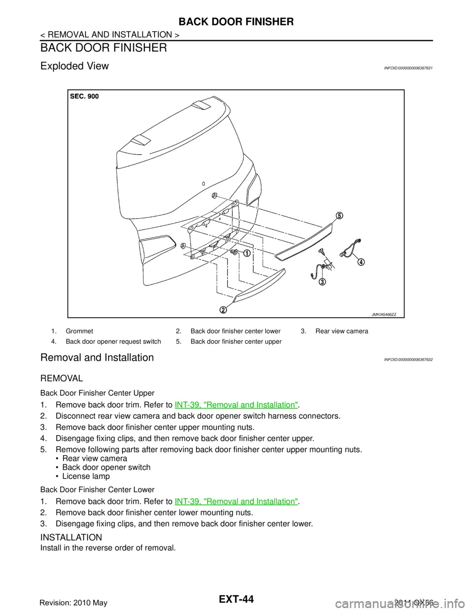
Exploded ViewINFOID:0000000006367631
Removal and InstallationINFOID:0000000006367632
REMOVAL
Back Door Finisher Center Upper
1. Remove back door trim. Refer to INT-39, "Removal and Installation".
2. Disconnect rear view camera and back door opener switch harness connectors.
3. Remove back door finisher center upper mounting nuts.
4. Disengage fixing clips, and then remove back door finisher center upper.
5. Remove following parts after removing back door finisher center upper mounting nuts. Rear view camera
Back door opener switch
License lamp
Back Door Finisher Center Lower
1. Remove back door trim. Refer to INT-39, "Removal and Installation".
2. Remove back door finisher center lower mounting nuts.
3. Disengage fixing clips, and then remove back door finisher center lower.
INSTALLATION
Install in the reverse order of removal.
1. Grommet 2. Back door finisher center lower 3. Rear view camera
4. Back door opener request switch 5. Back door finisher center upper
JMKIA5466ZZ
Revision: 2010 May2011 QX56
Page 2975 of 5598

HOW TO READ WIRING DIAGRAMSGI-11
< HOW TO USE THIS MANUAL >
C
DE
F
G H
I
J
K L
M B
GI
N
O P
SWITCH POSITIONS
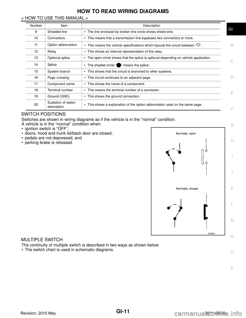
Switches are shown in wiring diagrams as if the vehicle is in the “normal” condition.
A vehicle is in the “normal” condition when:
ignition switch is “OFF”,
doors, hood and trunk lid/back door are closed,
pedals are not depressed, and
parking brake is released.
MULTIPLE SWITCH
The continuity of multiple switch is described in two ways as shown below.
The switch chart is used in schematic diagrams.
9 Shielded line The line enclosed by broken line circle shows shield wire.
10 Connectors This means that a transmission line bypasses two connectors or more.
11 Option abbreviation This means the vehicle specifications which layouts the circuit between “ ”.
12 Relay This shows an internal representation of the relay.
13 Optional splice The open circle shows that the splice is optional depending on vehicle application.
14 Splice The shaded circle “ ” means the splice.
15 System branch This shows that the circuit is branched to other systems.
16 Page crossing This circuit continues to an adjacent page.
17 Component name This shows the name of a component.
18 Terminal number This means the terminal number of a connector.
19 Ground (GND) This shows the ground connection.
20 Explation of option
description This shows a explanation of the option abbreviation used on the same page.
Number Item Description
SGI860
Revision: 2010 May2011 QX56