Page 1740 of 5598

DLK-204
< SYMPTOM DIAGNOSIS >
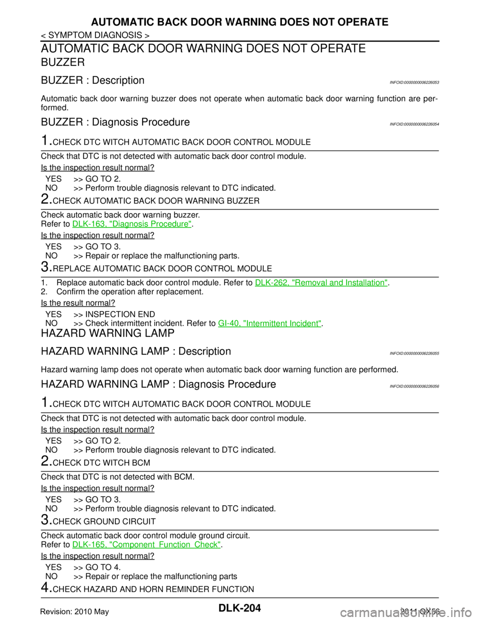
AUTOMATIC BACK DOOR WARNING DOES NOT OPERATE
AUTOMATIC BACK DOOR WARNING DOES NOT OPERATE
BUZZER
BUZZER : DescriptionINFOID:0000000006226053
Automatic back door warning buzzer does not operate when automatic back door warning function are per-
formed.
BUZZER : Diagnosis ProcedureINFOID:0000000006226054
1.CHECK DTC WITCH AUTOMATIC BACK DOOR CONTROL MODULE
Check that DTC is not detected with automatic back door control module.
Is the inspection result normal?
YES >> GO TO 2.
NO >> Perform trouble diagnosis relevant to DTC indicated.
2.CHECK AUTOMATIC BACK DOOR WARNING BUZZER
Check automatic back door warning buzzer.
Refer to DLK-163, "
Diagnosis Procedure".
Is the inspection result normal?
YES >> GO TO 3.
NO >> Repair or replace the malfunctioning parts.
3.REPLACE AUTOMATIC BACK DOOR CONTROL MODULE
1. Replace automatic back door control module. Refer to DLK-262, "
Removal and Installation".
2. Confirm the operation after replacement.
Is the result normal?
YES >> INSPECTION END
NO >> Check intermittent incident. Refer to GI-40, "
Intermittent Incident".
HAZARD WARNING LAMP
HAZARD WARNING LAMP : DescriptionINFOID:0000000006226055
Hazard warning lamp does not operate when automatic back door warning function are performed.
HAZARD WARNING LAMP : Diagnosis ProcedureINFOID:0000000006226056
1.CHECK DTC WITCH AUTOMATIC BACK DOOR CONTROL MODULE
Check that DTC is not detected with automatic back door control module.
Is the inspection result normal?
YES >> GO TO 2.
NO >> Perform trouble diagnosis relevant to DTC indicated.
2.CHECK DTC WITCH BCM
Check that DTC is not detected with BCM.
Is the inspection result normal?
YES >> GO TO 3.
NO >> Perform trouble diagnosis relevant to DTC indicated.
3.CHECK GROUND CIRCUIT
Check automatic back door control module ground circuit.
Refer to DLK-165, "
ComponentFunctionCheck".
Is the inspection result normal?
YES >> GO TO 4.
NO >> Repair or replace the malfunctioning parts
4.CHECK HAZARD AND HORN REMINDER FUNCTION
Revision: 2010 May2011 QX56
Page 1741 of 5598
AUTOMATIC BACK DOOR WARNING DOES NOT OPERATE
DLK-205
< SYMPTOM DIAGNOSIS >
C
D E
F
G H
I
J
L
M A
B
DLK
N
O P
Check hazard and horn reminder function.
Is the inspection result normal?
YES >> GO TO 5.
NO >> Refer to DLK-183, "
Diagnosis Procedure".
5.REPLACE AUTOMATIC BACK DOOR CONTROL MODULE
1. Replace automatic back door control module. Refer to DLK-262, "
Removal and Installation".
2. Confirm the operation after replacement.
Is the result normal?
YES >> INSPECTION END
NO >> Check intermittent incident. Refer to GI-40, "
Intermittent Incident".
Revision: 2010 May2011 QX56
Page 1742 of 5598

DLK-206
< SYMPTOM DIAGNOSIS >
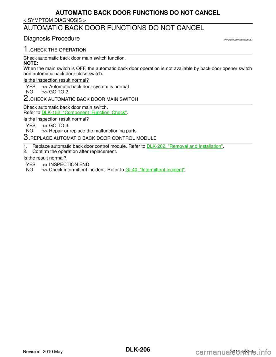
AUTOMATIC BACK DOOR FUNCTIONS DO NOT CANCEL
AUTOMATIC BACK DOOR FUNCTIONS DO NOT CANCEL
Diagnosis ProcedureINFOID:0000000006226057
1.CHECK THE OPERATION
Check automatic back door main switch function.
NOTE:
When the main switch is OFF, the automatic back door operation is not available by back door opener switch
and automatic back door close switch.
Is the inspection result normal?
YES >> Automatic back door system is normal.
NO >> GO TO 2.
2.CHECK AUTOMATIC BACK DOOR MAIN SWITCH
Check automatic back door main switch.
Refer to DLK-152, "
ComponentFunctionCheck".
Is the inspection result normal?
YES >> GO TO 3.
NO >> Repair or replace the malfunctioning parts.
3.REPLACE AUTOMATIC BACK DOOR CONTROL MODULE
1. Replace automatic back door control module. Refer to DLK-262, "
Removal and Installation".
2. Confirm the operation after replacement.
Is the result normal?
YES >> INSPECTION END
NO >> Check intermittent incident. Refer to GI-40, "
Intermittent Incident".
Revision: 2010 May2011 QX56
Page 1743 of 5598

AUTOMATIC BACK DOOR ANTI-PINCH FUNCTION DOES NOT OPERATE
DLK-207
< SYMPTOM DIAGNOSIS >
C
D E
F
G H
I
J
L
M A
B
DLK
N
O P
AUTOMATIC BACK DOOR ANTI-PINCH FUNCTION DOES NOT OPERATE
Diagnosis ProcedureINFOID:0000000006226058
1.CHECK POWER SUPPLY AND GROUND CIRCUIT
Check automatic back door control module power supply and ground circuit.
Refer to DLK-116, "
AUTOMATIC BACK DOOR CONTROL UNIT : Diagnosis Procedure".
Is the inspection result normal?
YES >> GO TO 2.
NO >> Repair or replace the malfunctioning parts.
2.CHECK TOUCH SENSOR LH
Check touch sensor LH.
Refer to DLK-159, "
LH : ComponentFunctionCheck".
Is the inspection result normal?
YES >> GO TO 3.
NO >> Repair or replace the malfunctioning parts.
3.CHECK TOUCH SENSOR RH
Check touch sensor RH.
Refer to DLK-158, "
RH : ComponentFunctionCheck".
Is the inspection result normal?
YES >> GO TO 4.
NO >> Repair or replace the malfunctioning parts.
4.REPLACE AUTOMATIC BACK DOOR CONTROL MODULE
1. Replace automatic back door control module. Refer to DLK-262, "
Removal and Installation".
2. Confirm the operation after replacement.
Is the result normal?
YES >> INSPECTION END
NO >> Check intermittent incident. Refer to GI-40, "
Intermittent Incident".
Revision: 2010 May2011 QX56
Page 1759 of 5598

FRONT FENDERDLK-223
< REMOVAL AND INSTALLATION >
C
DE
F
G H
I
J
L
M A
B
DLK
N
O P
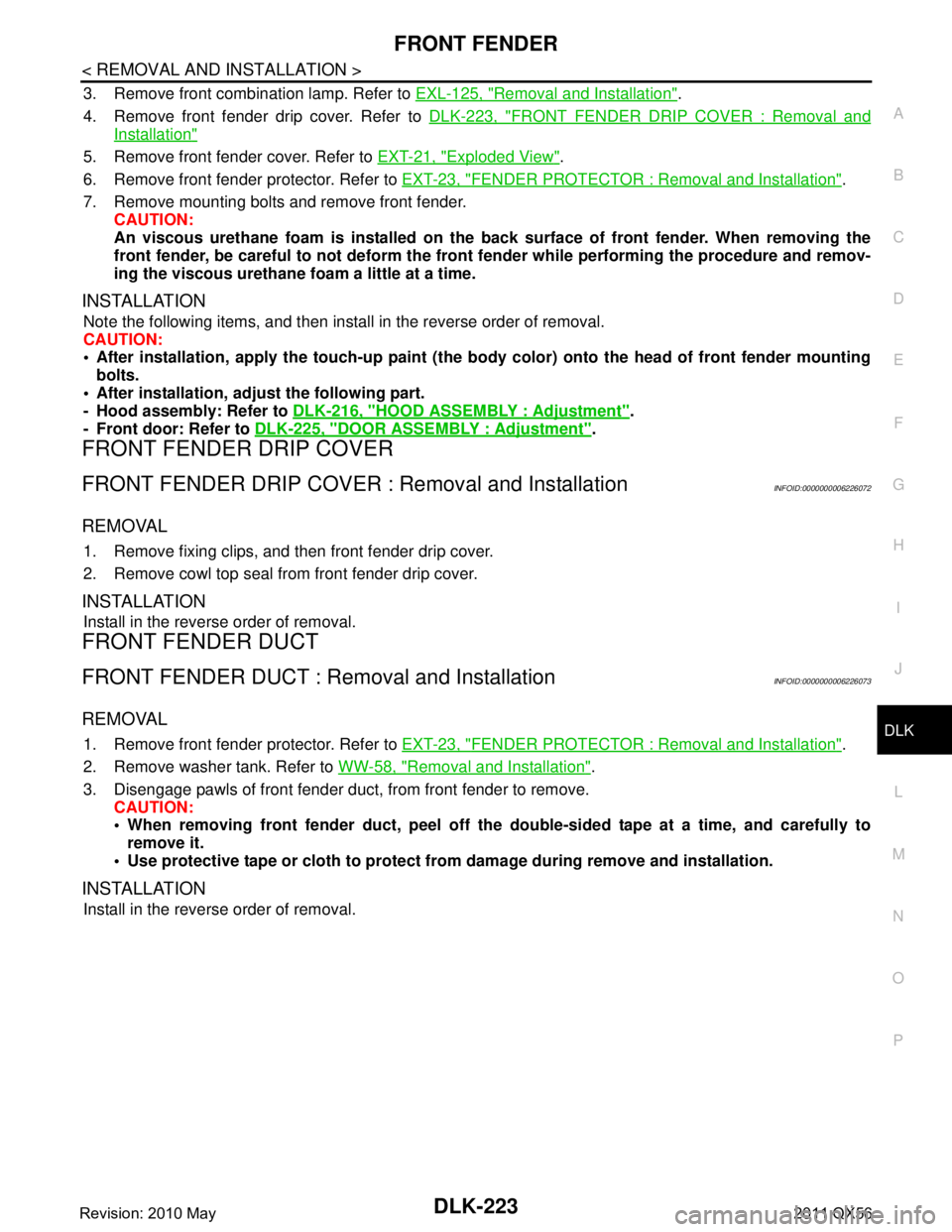
3. Remove front combination lamp. Refer to EXL-125, "Removal and Installation".
4. Remove front fender drip cover. Refer to DLK-223, "
FRONT FENDER DRIP COVER : Removal and
Installation"
5. Remove front fender cover. Refer to EXT-21, "Exploded View".
6. Remove front fender protector. Refer to EXT-23, "
FENDER PROTECTOR : Removal and Installation".
7. Remove mounting bolts and remove front fender. CAUTION:
An viscous urethane foam is installed on the back surface of front fender. When removing the
front fender, be careful to not deform the front fender while performing the procedure and remov-
ing the viscous urethane foam a little at a time.
INSTALLATION
Note the following items, and then install in the reverse order of removal.
CAUTION:
After installation, apply the touc h-up paint (the body color) onto the head of front fender mounting
bolts.
After installation, adju st the following part.
- Hood assembly: Refer to DLK-216, "
HOOD ASSEMBLY : Adjustment".
- Front door: Refer to DLK-225, "
DOOR ASSEMBLY : Adjustment".
FRONT FENDER DRIP COVER
FRONT FENDER DRIP COVER : Removal and InstallationINFOID:0000000006226072
REMOVAL
1. Remove fixing clips, and then front fender drip cover.
2. Remove cowl top seal from front fender drip cover.
INSTALLATION
Install in the reverse order of removal.
FRONT FENDER DUCT
FRONT FENDER DUCT : Removal and InstallationINFOID:0000000006226073
REMOVAL
1. Remove front fender protector. Refer to EXT-23, "FENDER PROTECTOR : Removal and Installation".
2. Remove washer tank. Refer to WW-58, "
Removal and Installation".
3. Disengage pawls of front fender duct, from front fender to remove. CAUTION:
When removing front fender duct, peel off the double-sided tape at a time, and carefully to
remove it.
Use protective tape or cloth to protect from damage during remove and installation.
INSTALLATION
Install in the reverse order of removal.
Revision: 2010 May2011 QX56
Page 1768 of 5598
DLK-232
< REMOVAL AND INSTALLATION >
BACK DOOR
BACK DOOR
Exploded ViewINFOID:0000000006226086
BACK DOOR ASSEMBLY
BACK DOOR ASSEMBLY : Removal and InstallationINFOID:0000000006226087
CAUTION:
Operate with two workers, because of its heavy weight.
Use protective tape or cloth to protect fr om damage during remove and installation.
REMOVAL
1. Remove stud ball of back door support rod. Refer to DLK-247, "BACK DOOR SUPPORT ROD : Removal
and Installation".
2. Remove roof garnish. Refer to INT-29, "
Removal and Installation".
1. Back door hinge 2. TORX bolt 3. Back door striker
4. Back door weather-strip 5. Stopper seal 6. Back door stay bracket
7. Back door stay 8. Back door lower bracket 9. Bumper rubber (side)
10. Bumper rubber bracket 11. Drain plug 12. Bumper rubber (lower)
13. Back door assembly
A : Center mark
B: Seam
Refer to GI-4, "
Components" for symbols in the figure.
JMKIA5482GB
Revision: 2010 May2011 QX56
Page 1769 of 5598

BACK DOORDLK-233
< REMOVAL AND INSTALLATION >
C
DE
F
G H
I
J
L
M A
B
DLK
N
O P
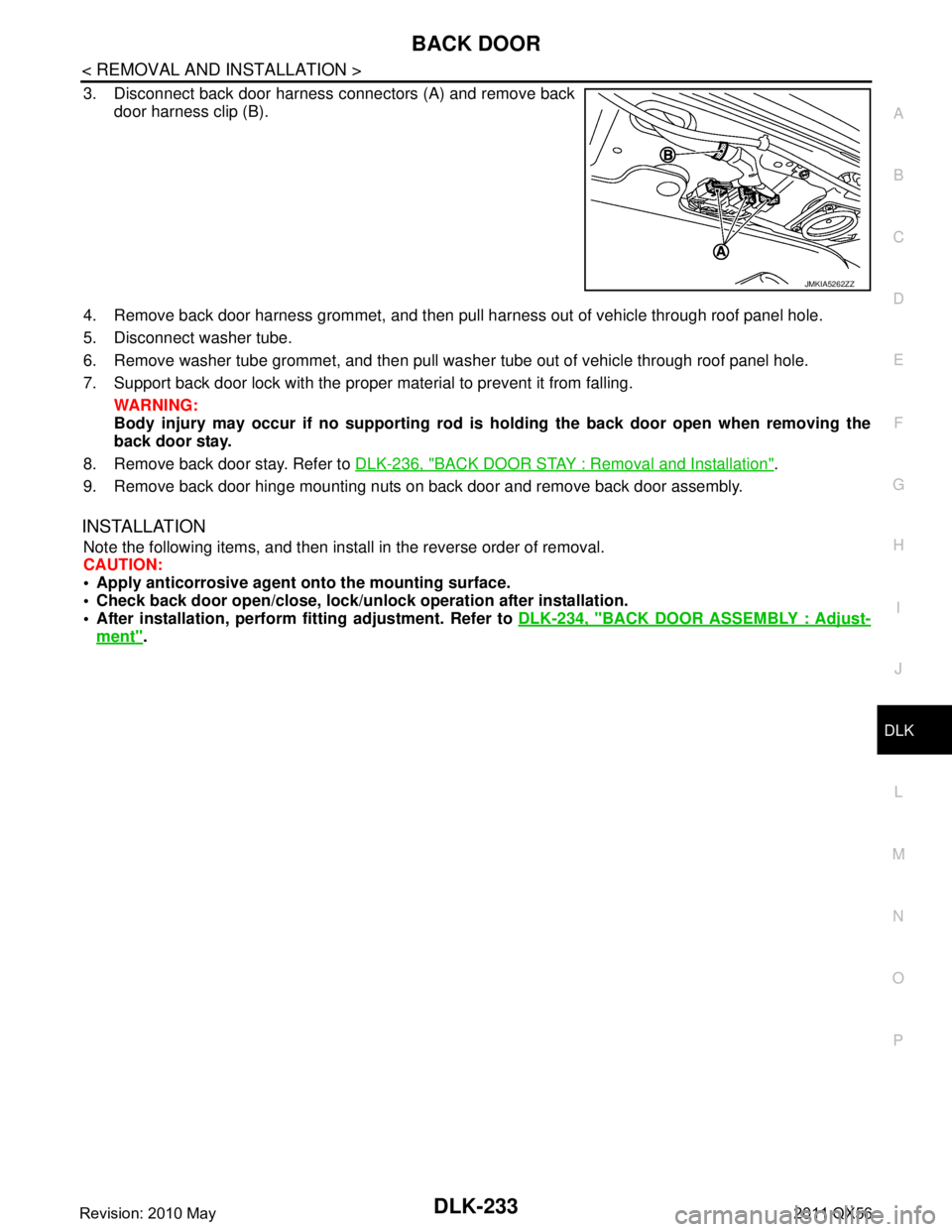
3. Disconnect back door harness connectors (A) and remove back door harness clip (B).
4. Remove back door harness grommet, and then pull harness out of vehicle through roof panel hole.
5. Disconnect washer tube.
6. Remove washer tube grommet, and then pull was her tube out of vehicle through roof panel hole.
7. Support back door lock with the proper material to prevent it from falling. WARNING:
Body injury may occur if no sup porting rod is holding the back door open when removing the
back door stay.
8. Remove back door stay. Refer to DLK-236, "
BACK DOOR STAY : Removal and Installation".
9. Remove back door hinge mounting nuts on back door and remove back door assembly.
INSTALLATION
Note the following items, and then install in the reverse order of removal.
CAUTION:
Apply anticorrosive agen t onto the mounting surface.
Check back door open/close, lock/un lock operation after installation.
After installation, perform fitting adjustment. Refer to DLK-234, "
BACK DOOR ASSEMBLY : Adjust-
ment".
JMKIA5262ZZ
Revision: 2010 May2011 QX56
Page 1770 of 5598
DLK-234
< REMOVAL AND INSTALLATION >
BACK DOOR
BACK DOOR ASSEMBLY : Adjustment
INFOID:0000000006226088
Check the clearance and the surface height between back door and each part by visually and touching.
If the clearance and the surface height are out of spec ification, adjust them according to the procedures
shown below.
1. Back door assembly 2. Back door hinge 3. Back door striker
4. TORX bolt 5. Bumper rubber 6. Roof
7. Rear roof spoiler 8. Body side outer 9. Back door glass
10. Rear combination lamp 11. Back up lamp 12. Rear bumper fascia
Refer to GI-4, "
Components" for symbols in the figure.
JMKIA5483GB
Revision: 2010 May2011 QX56