Page 3805 of 5598
MWI-62
< DTC/CIRCUIT DIAGNOSIS >
B2267 ENGINE SPEED
B2267 ENGINE SPEED
DescriptionINFOID:0000000006221737
The engine speed signal is transmitted from ECM to the combination meter via CAN communication.
DTC LogicINFOID:0000000006221738
DTC DETECTION LOGIC
Diagnosis ProcedureINFOID:0000000006221739
1.PERFORM SELF-DIAGNOSIS OF ECM
Perform “Self Diagnostic Result” of ECM, and repair or replace malfunctioning parts.
>> Refer to EC-98, "
DTC Index".
DTCDisplay contents of
CONSULT-III Diagnostic item is detected when... Probable malfunction location
B2267 ENGINE SPEED ECM continuously transmits abnormal engine
speed signals for 2 seconds or more Crankshaft position sensor (POS)
ECM
Revision: 2010 May2011 QX56
Page 3806 of 5598
MWI
B2268 WATER TEMPMWI-63
< DTC/CIRCUIT DIAGNOSIS >
C
DE
F
G H
I
J
K L
M B A
O P
B2268 WATER TEMP
DescriptionINFOID:0000000006221740
The engine coolant temperature signal is transmitted from ECM to the combination meter via CAN communi-
cation.
DTC LogicINFOID:0000000006221741
DTC DETECTION LOGIC
Diagnosis ProcedureINFOID:0000000006221742
1.PERFORM SELF-DIAGNOSIS OF ECM
Perform “Self Diagnosis Result” of ECM, and repair or replace malfunctioning parts.
>> Refer to EC-98, "
DTC Index".
DTCDisplay contents of
CONSULT-III Diagnostic item is detected when... Probable malfunction location
B2268 WATER TEMP ECM continuously transmits abnormal engine
coolant temperature signals for 60 seconds or
more Engine coolant temperature sensor
ECM
Revision: 2010 May2011 QX56
Page 3812 of 5598

MWI
FUEL LEVEL SENSOR SIGNAL CIRCUITMWI-69
< DTC/CIRCUIT DIAGNOSIS >
C
DE
F
G H
I
J
K L
M B A
O P
FUEL LEVEL SENSOR SIGNAL CIRCUIT
Component Function CheckINFOID:0000000006221748
1.CHECK COMBINATION METER OUTPUT SIGNAL
Select the “Data Monitor” for the “METER/M&A” and compare the “FUEL ME TER” monitor value with the fuel
gauge reading on the combination meter.
Does monitor value match fuel gauge reading?
YES >> INSPECTION END
NO >> Replace combination meter. Refer to MWI-85, "
Removal and Installation".
Diagnosis ProcedureINFOID:0000000006221749
1.CHECK COMBINATION METER INPUT SIGNAL
1. Turn ignition switch ON.
2. Check voltage between combination meter harness connector and ground.
Does it match fuel gauge reading?
YES >> GO TO 2.
NO >> Replace the combination meter. Refer to MWI-85, "
Removal and Installation".
2.CHECK FUEL LEVEL SENSOR CIRCUIT
1. Turn ignition switch OFF.
2. Disconnect combination meter connector and fuel level sensor unit connector.
3. Check continuity between combination meter harnes s connector and fuel level sensor unit harness con-
nector.
4. Check continuity between combination meter harness connector and ground.
Fuel gauge indication position Reference value of data monitor [L] 1 Approx. 101.8
3/4 Approx. 77.3
1/2 Approx. 52.3
1/4 Approx. 27.3 0Approx. 2.3
Te r m i n a l s
Vo l ta g e
(Approx.)
(+) (
−)
Combination meter
Ground
Connector Terminal
M34 34
JSNIA3013ZZ
Combination meter Fuel level sensor unit Continuity
Connector Terminal Connector Terminal
M34 34 C5 2 Existed
Revision: 2010 May2011 QX56
Page 3813 of 5598

MWI-70
< DTC/CIRCUIT DIAGNOSIS >
FUEL LEVEL SENSOR SIGNAL CIRCUIT
Is the inspection result normal?
YES >> GO TO 3.
NO >> Repair harness or connector.
3.CHECK FUEL LEVEL SENSOR GROUND CIRCUIT
Check continuity between fuel level sensor unit harness connector and combination meter harness connector.
Is the inspection result normal?
YES >> INSPECTION END
NO >> Repair harness or connector.
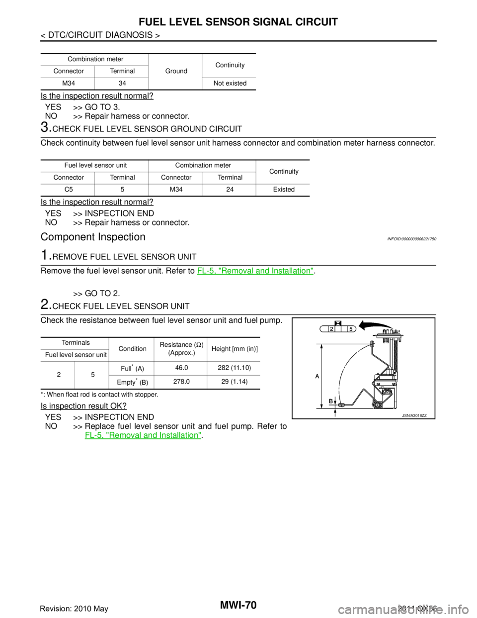
Component InspectionINFOID:0000000006221750
1.REMOVE FUEL LEVEL SENSOR UNIT
Remove the fuel level sensor unit. Refer to FL-5, "
Removal and Installation".
>> GO TO 2.
2.CHECK FUEL LEVEL SENSOR UNIT
Check the resistance between fuel level sensor unit and fuel pump.
*: When float rod is contact with stopper.
Is inspection result OK?
YES >> INSPECTION END
NO >> Replace fuel level sensor unit and fuel pump. Refer to FL-5, "
Removal and Installation".
Combination meter
GroundContinuity
Connector Terminal
M34 34 Not existed
Fuel level sensor unit Combination meter Continuity
Connector Terminal Connector Terminal
C5 5 M34 24 Existed
Te r m i n a l s ConditionResistance (
Ω)
(Approx.) Height [mm (in)]
Fuel level sensor unit
25 Full
* (A)
46.0 282 (11.10)
Empty
* (B) 278.0 29 (1.14)
JSNIA3018ZZ
Revision: 2010 May2011 QX56
Page 3818 of 5598

MWI
THE FUEL GAUGE INDICATOR DOES NOT OPERATE
MWI-75
< SYMPTOM DIAGNOSIS >
C
D E
F
G H
I
J
K L
M B A
O P
SYMPTOM DIAGNOSIS
THE FUEL GAUGE INDICA TOR DOES NOT OPERATE
DescriptionINFOID:0000000006221757
Fuel gauge will not indicate from a certain position.
Diagnosis ProcedureINFOID:0000000006221758
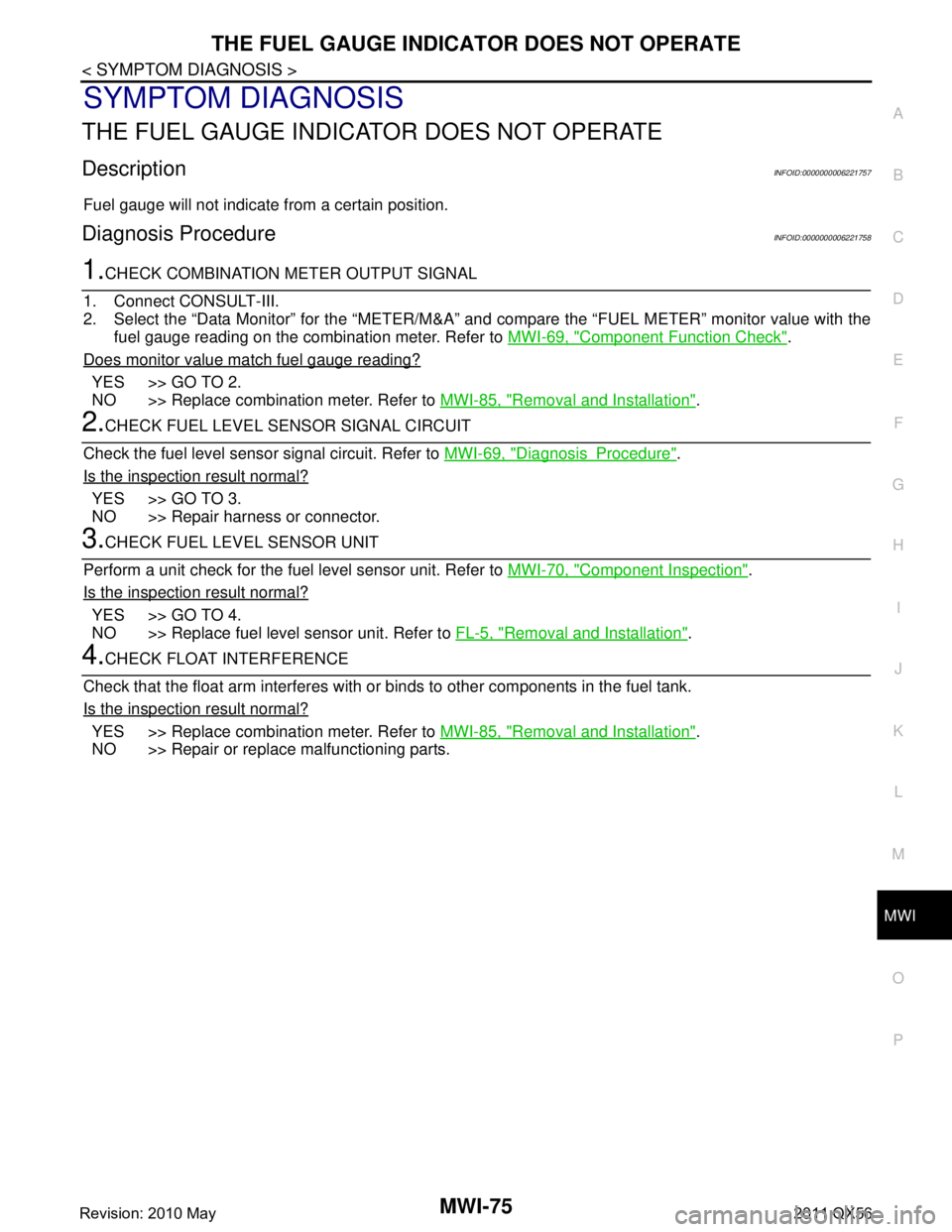
1.CHECK COMBINATION METER OUTPUT SIGNAL
1. Connect CONSULT-III.
2. Select the “Data Monitor” for the “METER/M&A” and compare the “FUEL METER” monitor value with the
fuel gauge reading on the combination meter. Refer to MWI-69, "
Component Function Check".
Does monitor value match fuel gauge reading?
YES >> GO TO 2.
NO >> Replace combination meter. Refer to MWI-85, "
Removal and Installation".
2.CHECK FUEL LEVEL SENSOR SIGNAL CIRCUIT
Check the fuel level sensor signal circuit. Refer to MWI-69, "
DiagnosisProcedure".
Is the inspection result normal?
YES >> GO TO 3.
NO >> Repair harness or connector.
3.CHECK FUEL LEVEL SENSOR UNIT
Perform a unit check for the fuel level sensor unit. Refer to MWI-70, "
Component Inspection".
Is the inspection result normal?
YES >> GO TO 4.
NO >> Replace fuel level sensor unit. Refer to FL-5, "
Removal and Installation".
4.CHECK FLOAT INTERFERENCE
Check that the float arm interferes with or binds to other components in the fuel tank.
Is the inspection result normal?
YES >> Replace combination meter. Refer to MWI-85, "Removal and Installation".
NO >> Repair or replace malfunctioning parts.
Revision: 2010 May2011 QX56
Page 3826 of 5598

MWI
THE AMBIENT TEMPERATURE DISPLAY IS INCORRECT
MWI-83
< SYMPTOM DIAGNOSIS >
C
D E
F
G H
I
J
K L
M B A
O P
THE AMBIENT TEMPERATURE DISPLAY IS INCORRECT
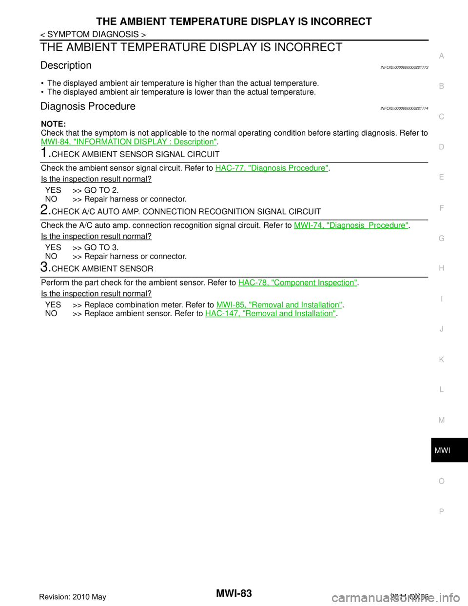
DescriptionINFOID:0000000006221773
The displayed ambient air temperature is higher than the actual temperature.
The displayed ambient air temperature is lower than the actual temperature.
Diagnosis ProcedureINFOID:0000000006221774
NOTE:
Check that the symptom is not applicable to the no rmal operating condition before starting diagnosis. Refer to
MWI-84, "
INFORMATION DISPLAY : Description".
1.CHECK AMBIENT SENSOR SIGNAL CIRCUIT
Check the ambient sensor signal circuit. Refer to HAC-77, "
Diagnosis Procedure".
Is the inspection result normal?
YES >> GO TO 2.
NO >> Repair harness or connector.
2.CHECK A/C AUTO AMP. CONNECTION RECOGNITION SIGNAL CIRCUIT
Check the A/C auto amp. connection re cognition signal circuit. Refer to MWI-74, "
DiagnosisProcedure".
Is the inspection result normal?
YES >> GO TO 3.
NO >> Repair harness or connector.
3.CHECK AMBIENT SENSOR
Perform the part check for t he ambient sensor. Refer to HAC-78, "
Component Inspection".
Is the inspection result normal?
YES >> Replace combination meter. Refer to MWI-85, "Removal and Installation".
NO >> Replace ambient sensor. Refer to HAC-147, "
Removal and Installation".
Revision: 2010 May2011 QX56
Page 3827 of 5598
MWI-84
< SYMPTOM DIAGNOSIS >
NORMAL OPERATING CONDITION
NORMAL OPERATING CONDITION
INFORMATION DISPLAY
INFORMATION DISPLAY : DescriptionINFOID:0000000006221775
AMBIENT AIR TEMPERATURE
The displayed ambient air temperature on the information display may differ from the actual temperature
because it is a corrected value calculated from the ambi ent sensor signal by the combination meter. Refer to
MWI-20, "
INFORMATION DISPLAY : System Description" for details on the correction process.
DISTANCE TO EMPTY
The calculated distance to empty may differ from the actual distance to empty if the refueling amount is
approximately 15 (4 US gal, 3-1/4 Imp gal) or less. Th is is because the refuel control (moves the fuel gauge
needle quicker than normal judging that the driver is refueling the vehicle) is not performing.
Revision: 2010 May2011 QX56
Page 3844 of 5598
![INFINITI QX56 2011 Factory Service Manual
PCS
PRECAUTIONSPCS-3
< PRECAUTION > [IPDM E/R]
C
D
E
F
G H
I
J
K L
B A
O P
N
PRECAUTION
PRECAUTIONS
Precaution for Supplemental
Restraint System (SRS) "AIR BAG" and "SEAT BELT
PRE-TENSIONER"
INFOID INFINITI QX56 2011 Factory Service Manual
PCS
PRECAUTIONSPCS-3
< PRECAUTION > [IPDM E/R]
C
D
E
F
G H
I
J
K L
B A
O P
N
PRECAUTION
PRECAUTIONS
Precaution for Supplemental
Restraint System (SRS) "AIR BAG" and "SEAT BELT
PRE-TENSIONER"
INFOID](/manual-img/42/57033/w960_57033-3843.png)
PCS
PRECAUTIONSPCS-3
< PRECAUTION > [IPDM E/R]
C
D
E
F
G H
I
J
K L
B A
O P
N
PRECAUTION
PRECAUTIONS
Precaution for Supplemental
Restraint System (SRS) "AIR BAG" and "SEAT BELT
PRE-TENSIONER"
INFOID:0000000006220159
The Supplemental Restraint System such as “A IR BAG” and “SEAT BELT PRE-TENSIONER”, used along
with a front seat belt, helps to reduce the risk or severi ty of injury to the driver and front passenger for certain
types of collision. This system includes seat belt switch inputs and dual stage front air bag modules. The SRS
system uses the seat belt switches to determine the front air bag deployment, and may only deploy one front
air bag, depending on the severity of a collision and whether the front occupants are belted or unbelted.
Information necessary to service the system safely is included in the “SRS AIR BAG” and “SEAT BELT” of this
Service Manual.
WARNING:
• To avoid rendering the SRS inoper ative, which could increase the risk of personal injury or death in
the event of a collision that would result in air ba g inflation, all maintenance must be performed by
an authorized NISSAN/INFINITI dealer.
Improper maintenance, including in correct removal and installation of the SRS, can lead to personal
injury caused by unintentional act ivation of the system. For removal of Spiral Cable and Air Bag
Module, see the “SRS AIR BAG”.
Do not use electrical test equipm ent on any circuit related to the SRS unless instructed to in this
Service Manual. SRS wiring harnesses can be identi fied by yellow and/or orange harnesses or har-
ness connectors.
PRECAUTIONS WHEN USING POWER TOOLS (AIR OR ELECTRIC) AND HAMMERS
WARNING:
When working near the Air Bag Diagnosis Sensor Unit or other Air Bag System sensors with the
ignition ON or engine running, DO NOT use air or electric power tools or strike near the sensor(s)
with a hammer. Heavy vibration could activate the sensor(s) and deploy the air bag(s), possibly
causing serious injury.
When using air or electric power tools or hammers , always switch the ignition OFF, disconnect the
battery, and wait at least 3 minutes before performing any service.
Revision: 2010 May2011 QX56