2011 INFINITI QX56 sensor
[x] Cancel search: sensorPage 3749 of 5598
MWI-6
< SYSTEM DESCRIPTION >
COMPONENT PARTS
SYSTEM DESCRIPTION
COMPONENT PARTS
METER SYSTEM
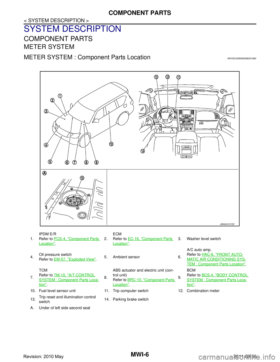
METER SYSTEM : Component Parts LocationINFOID:0000000006221690
1.IPDM E/R
Refer to
PCS-4, "Component Parts
Location". 2.
ECM
Refer to
EC-16, "
Component Parts
Location". 3. Washer level switch
4. Oil pressure switch
Refer to
EM-57, "
Exploded View".5. Ambient sensor 6. A/C auto amp.
Refer to
HAC-6, "
FRONT AUTO-
MATIC AIR CONDITIONING SYS-
TEM : Component Parts Location".
7. TCM
Refer to
TM-10, "
A/T CONTROL
SYSTEM : Componen t Parts Loca-
tion". 8.ABS actuator and electric unit (con-
trol unit)
Refer to
BRC-10, "
Component Parts
Location". 9.BCM
Refer to
BCS-4, "
BODY CONTROL
SYSTEM : Component Parts Loca-
tion".
10. Fuel level sensor unit 11. Trip computer switch 12. Combination meter
13. Trip reset and illumination control
switch 14. Parking brake switch
A. Under of left side second seat
JSNIA3157ZZ
Revision: 2010 May2011 QX56
Page 3750 of 5598

MWI
COMPONENT PARTSMWI-7
< SYSTEM DESCRIPTION >
C
DE
F
G H
I
J
K L
M B A
O P
METER SYSTEM : Com ponent DescriptionINFOID:0000000006221691
CLOCK
Unit Description
Combination meter Controls the following with the signals received from each unit via CAN communication and the sig-
nals from switches and sensors.
Speedometer
Tachometer
Engine coolant temperature gauge
Fuel gauge
Engine oil pressure gauge
Voltmeter
Warning lamps
Indicator lamps
Meter illumination control
Meter effect function
Information display
Trip computer switch Transmits the following signals to the combination meter.
Enter switch signal
Select switch signal
Trip reset and illumination con-
trol switch Transmits the following signals to the combination meter.
Trip reset switch signal
Illumination control switch signal (+)
Illumination control switch signal (
−)
ECM Transmits the following signals to the combination meter via CAN communication.
Engine speed signal
Engine coolant temperature signal
Engine status signal
Fuel consumption monitor signal
ABS actuator and electric unit
(control unit) Transmits the vehicle speed signal to the combination meter via CAN communication.
IPDM E/R Transmits the oil pressure switch signal to the BCM via CAN communication.
BCM Transmits the following signals to the combination meter via CAN communication.
Oil pressure switch signal
Position light request signal
Dimmer signal
Door switch signal
Meter ring illumination request signal
Starter relay status signal
TCM Transmits the shift position signal to the combination meter via CAN communication.
A/T shift selector Transmits the following signals to the combination meter.
Manual mode signal
Non-manual mode signal
Manual mode shift up signal
Manual mode shift down signal
Fuel level sensor unit Transmits the fuel level sensor signal to the combination meter.
Oil pressure switch Transmits the oil pressure switch signal to the IPDM E/R.
Ambient sensor Transmits the ambient sensor signal to the combination meter.
A/C auto amp. Transmits the A/C auto amp. connection recognition signal to the combination meter.
Parking brake switch Transmits the parking brake switch signal to the combination meter.
Washer level switch Transmits the washer level switch signal to the combination meter.
Revision: 2010 May2011 QX56
Page 3752 of 5598

MWI
SYSTEMMWI-9
< SYSTEM DESCRIPTION >
C
DE
F
G H
I
J
K L
M B A
O P
SYSTEM
METER SYSTEM
METER SYSTEM : System DiagramINFOID:0000000006221693
METER SYSTEM : System DescriptionINFOID:0000000006221694
COMBINATION METER
The combination meter receives necessary signals from each unit, switch, and sensor to control the follow-
ing functions.
- Measuring instruments
- Warning lamps
- Indicator lamps
- Meter illumination control
- Meter effect function
- Information display
The combination meter incorporates a buzzer func tion that sounds an audible alarm with the integrated
buzzer device. Refer to WCS-5, "
Combination Meter" for further details.
The combination meter includes an on board diagnosis function.
The combination meter can be diagnosed with CONSULT-III.
METER CONTROL FUNCTION LIST
JSNIA2995GB
Revision: 2010 May2011 QX56
Page 3756 of 5598
MWI
SYSTEMMWI-13
< SYSTEM DESCRIPTION >
C
DE
F
G H
I
J
K L
M B A
O P
SPEEDOMETER
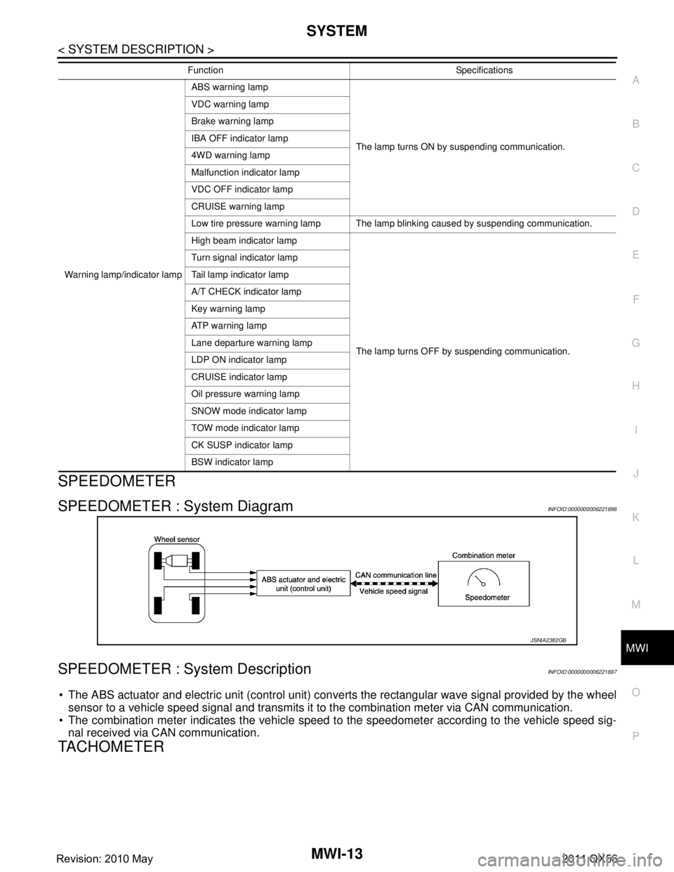
SPEEDOMETER : System DiagramINFOID:0000000006221696
SPEEDOMETER : System DescriptionINFOID:0000000006221697
The ABS actuator and electric unit (control unit) conv erts the rectangular wave signal provided by the wheel
sensor to a vehicle speed signal and transmits it to the combination meter via CAN communication.
The combination meter indicates the vehicle speed to the speedometer according to the vehicle speed sig-
nal received via CAN communication.
TACHOMETER
Warning lamp/indicator lamp ABS warning lamp
The lamp turns ON by suspending communication.
VDC warning lamp
Brake warning lamp
IBA OFF indicator lamp
4WD warning lamp
Malfunction indicator lamp
VDC OFF indicator lamp
CRUISE warning lamp
Low tire pressure warning lamp The lamp blinking caused by suspending communication.
High beam indicator lamp
The lamp turns OFF by suspending communication.
Turn signal indicator lamp
Tail lamp indicator lamp
A/T CHECK indicator lamp
Key warning lamp
AT P w a r n i n g l a m p
Lane departure warning lamp
LDP ON indicator lamp
CRUISE indicator lamp
Oil pressure warning lamp
SNOW mode indicator lamp
TOW mode indicator lamp
CK SUSP indicator lamp
BSW indicator lamp
Function Specifications
JSNIA2382GB
Revision: 2010 May2011 QX56
Page 3757 of 5598
MWI-14
< SYSTEM DESCRIPTION >
SYSTEM
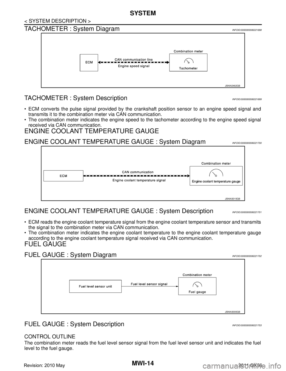
TACHOMETER : System Diagram
INFOID:0000000006221698
TACHOMETER : System DescriptionINFOID:0000000006221699
ECM converts the pulse signal provided by the crankshaft position sensor to an engine speed signal and
transmits it to the combination meter via CAN communication.
The combination meter indicates the engine speed to the tachometer according to the engine speed signal
received via CAN communication.
ENGINE COOLANT TEMPERATURE GAUGE
ENGINE COOLANT TEMPERATURE GAUGE : System DiagramINFOID:0000000006221700
ENGINE COOLANT TEMPERATURE GAUGE : System DescriptionINFOID:0000000006221701
ECM reads the engine coolant temperature signal from the engine coolant temperature sensor and transmits
the signal to the combination meter via CAN communication.
The combination meter indicates the engine coolant temperature to the engine coolant temperature gauge
according to the engine coolant temperature signal received via CAN communication.
FUEL GAUGE
FUEL GAUGE : System DiagramINFOID:0000000006221702
FUEL GAUGE : System DescriptionINFOID:0000000006221703
CONTROL OUTLINE
The combination meter reads the fuel level sensor signal from the fuel level sensor unit and indicates the fuel
level to the fuel gauge.
JSNIA2462GB
JSNIA3015GB
JSNIA3000GB
Revision: 2010 May2011 QX56
Page 3763 of 5598
MWI-20
< SYSTEM DESCRIPTION >
SYSTEM
INFORMATION DISPLAY : System Description
INFOID:0000000006221717
DESCRIPTION
The combination meter receives signals necessary for controlling the operation of the information display from each unit, sensor and switch.
The combination meter incorporates a trip computer t hat displays the warning/information according to the
information received from each unit, sensor and switch.
The combination meter shows the following functions on the information display.
- Odo/trip meter
- Shift position indicator
- Trip computer
- Interrupt indication
- Warning check indication
- Setting
ODO/TRIP METER
The ABS actuator and electric unit (control unit) r eads the rectangular wave signal provided by the wheel
sensor and transmits the vehicle speed signal to the combination meter via CAN communication.
The combination meter converts the vehicle speed signal received via CAN communication to mileage, and it displays the accumulated mileage on the information display.
SHIFT POSITION INDICATOR
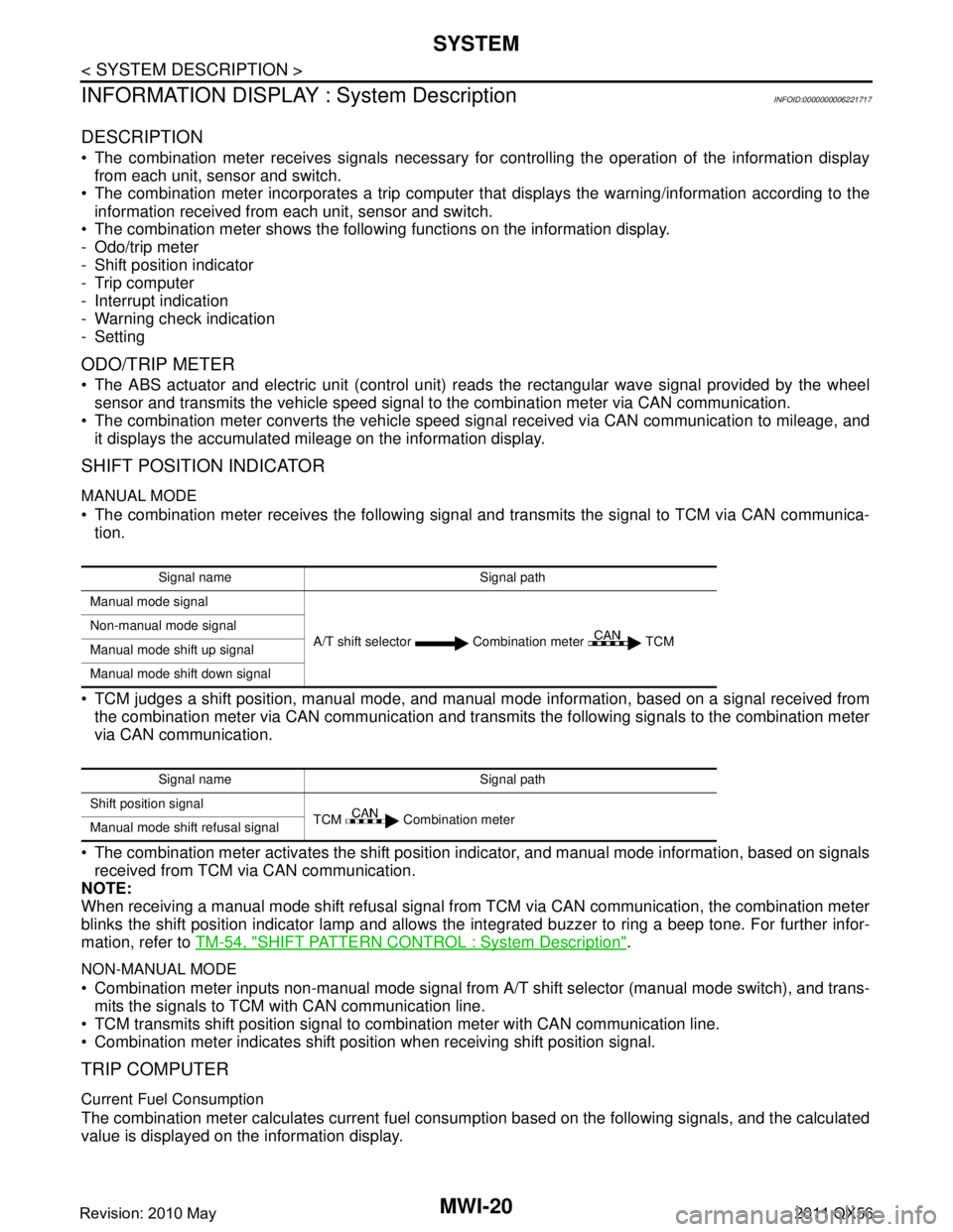
MANUAL MODE
The combination meter receives the following signal and transmits the signal to TCM via CAN communica-tion.
TCM judges a shift position, manual mode, and manual mode information, based on a signal received from
the combination meter via CAN communication and transmi ts the following signals to the combination meter
via CAN communication.
The combination meter activates the shift position indicator, and manual mode information, based on signals received from TCM via CAN communication.
NOTE:
When receiving a manual mode shift refusal signal from TCM via CAN communication, the combination meter
blinks the shift position indicator lamp and allows the integrated buzzer to ring a beep tone. For further infor-
mation, refer to TM-54, "
SHIFT PATTERN CONTROL : System Description".
NON-MANUAL MODE
Combination meter inputs non-manual mode signal from A/T shift selector (manual mode switch), and trans-
mits the signals to TCM with CAN communication line.
TCM transmits shift position signal to combination meter with CAN communication line.
Combination meter indicates shift position when receiving shift position signal.
TRIP COMPUTER
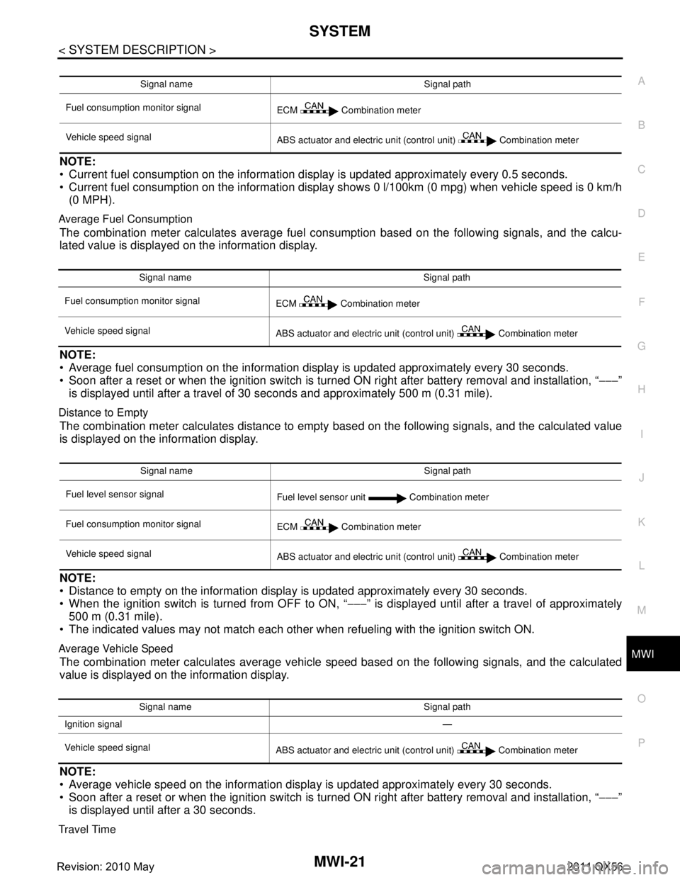
Current Fuel Consumption
The combination meter calculates current fuel cons umption based on the following signals, and the calculated
value is displayed on the information display.
Signal name Signal path
Manual mode signal
A/T shift selector Combination meter TCM
Non-manual mode signal
Manual mode shift up signal
Manual mode shift down signal
Signal name Signal path
Shift position signal TCM Combination meter
Manual mode shift refusal signal
Revision: 2010 May2011 QX56
Page 3764 of 5598
MWI
SYSTEMMWI-21
< SYSTEM DESCRIPTION >
C
DE
F
G H
I
J
K L
M B A
O PNOTE:
Current fuel consumption on the information di splay is updated approximately every 0.5 seconds.
Current fuel consumption on the information displa y shows 0 l/100km (0 mpg) when vehicle speed is 0 km/h
(0 MPH).
Average Fuel Consumption
The combination meter calculates average fuel c onsumption based on the following signals, and the calcu-
lated value is displayed on the information display.
NOTE:
Average fuel consumption on the information display is updated approximately every 30 seconds.
Soon after a reset or when the ignition switch is turned ON right after battery removal and installation, “ −−−”
is displayed until after a travel of 30 seconds and approximately 500 m (0.31 mile).
Distance to Empty
The combination meter calculates distance to empty based on the following signals, and the calculated value
is displayed on the information display.
NOTE:
Distance to empty on the information display is updated approximately every 30 seconds.
When the ignition switch is turned from OFF to ON, “ −−−” is displayed until after a travel of approximately
500 m (0.31 mile).
The indicated values may not match each other when refueling with the ignition switch ON.
Average Vehicle Speed
The combination meter calculates average vehicle speed based on the following signals, and the calculated
value is displayed on the information display.
NOTE:
Average vehicle speed on the information disp lay is updated approximately every 30 seconds.
Soon after a reset or when the ignition switch is turned ON right after battery removal and installation, “ −−−”
is displayed until after a 30 seconds.
Travel Time
Signal name Signal path
Fuel consumption monitor signal ECM Combination meter
Vehicle speed signal ABS actuator and electric unit (control unit) Combination meter
Signal name Signal path
Fuel consumption monitor signal ECM Combination meter
Vehicle speed signal ABS actuator and electric unit (control unit) Combination meter
Signal name Signal path
Fuel level sensor signal Fuel level sensor unit Combination meter
Fuel consumption monitor signal ECM Combination meter
Vehicle speed signal ABS actuator and electric unit (control unit) Combination meter
Signal name Signal path
Ignition signal —
Vehicle speed signal ABS actuator and electric unit (control unit) Combination meter
Revision: 2010 May2011 QX56
Page 3765 of 5598
MWI-22
< SYSTEM DESCRIPTION >
SYSTEM
The combination meter measures and displays travel time (ignition switch ON time).
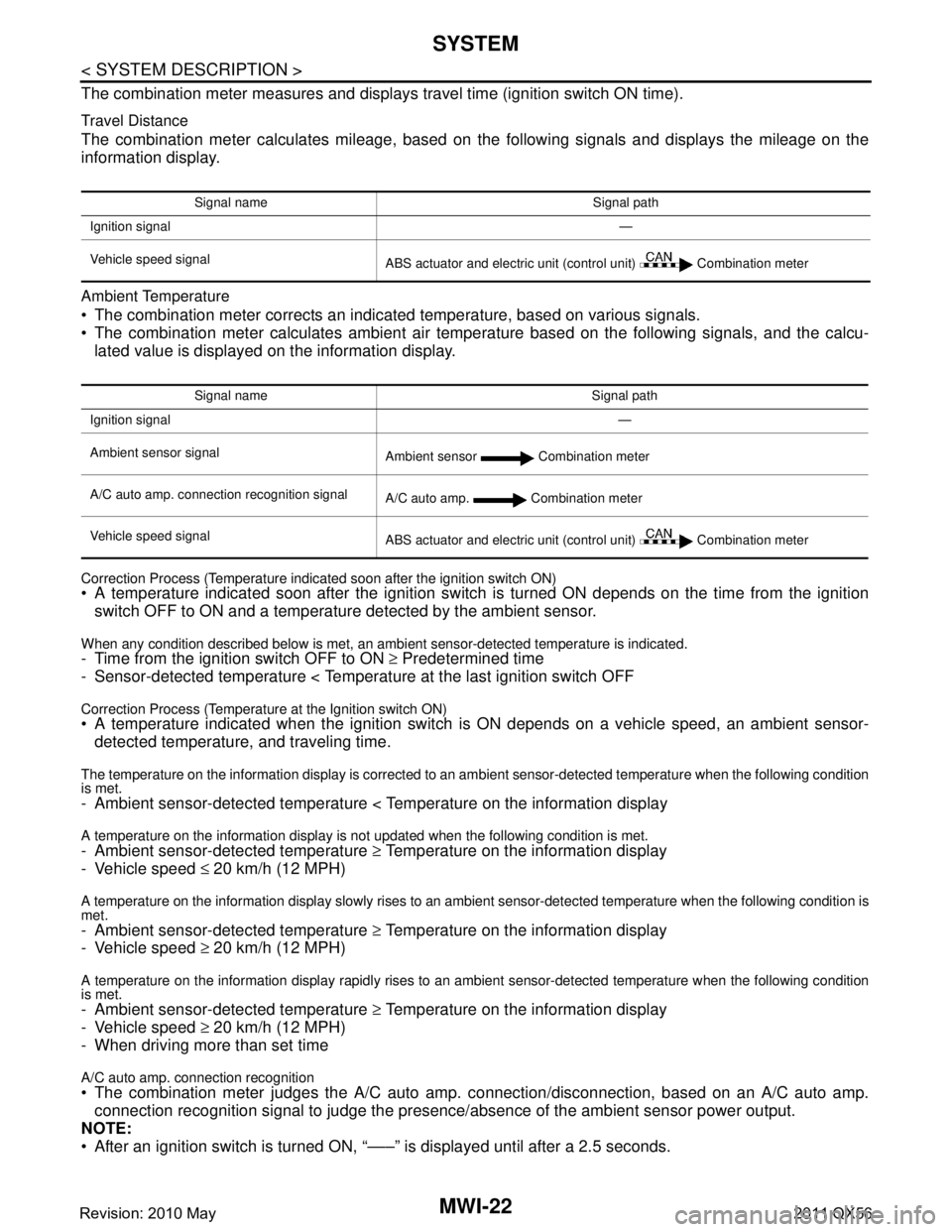
Travel Distance
The combination meter calculates mileage, based on the following signals and displays the mileage on the
information display.
Ambient Temperature
The combination meter corrects an indicated temperature, based on various signals.
The combination meter calculates ambient air temperature based on the following signals, and the calcu-
lated value is displayed on the information display.
Correction Process (Temperature indicated soon after the ignition switch ON) A temperature indicated soon after the ignition switch is turned ON depends on the time from the ignition switch OFF to ON and a temperatur e detected by the ambient sensor.
When any condition described below is met, an ambient sensor-detected temperature is indicated.- Time from the ignition switch OFF to ON ≥ Predetermined time
- Sensor-detected temperature < Temperat ure at the last ignition switch OFF
Correction Process (Temperature at the Ignition switch ON) A temperature indicated when the ignition switch is ON depends on a vehicle speed, an ambient sensor-
detected temperature, and traveling time.
The temperature on the information display is corrected to an am bient sensor-detected temperature when the following condition
is met.
- Ambient sensor-detected temperature < Temperature on the information display
A temperature on the information display is no t updated when the following condition is met.
- Ambient sensor-detected temperature ≥ Temperature on the information display
- Vehicle speed ≤ 20 km/h (12 MPH)
A temperature on the information display slowly rises to an ambient sensor-detected temperature when the following condition is
met.
- Ambient sensor-detected temperature ≥ Temperature on the information display
- Vehicle speed ≥ 20 km/h (12 MPH)
A temperature on the information display rapidly rises to an ambient sensor-detected temperature when the following condition
is met.
- Ambient sensor-detected temperature ≥ Temperature on the information display
- Vehicle speed ≥ 20 km/h (12 MPH)
- When driving more than set time
A/C auto amp. connection recognition
The combination meter judges the A/C auto amp. connection/disconnection, based on an A/C auto amp.
connection recognition signal to judge the presence/ absence of the ambient sensor power output.
NOTE:
After an ignition switch is turned ON, “–––” is displayed until after a 2.5 seconds.
Signal name Signal path
Ignition signal —
Vehicle speed signal ABS actuator and electric unit (control unit) Combination meter
Signal name Signal path
Ignition signal —
Ambient sensor signal Ambient sensor Combination meter
A/C auto amp. connection recognition signal A/C auto amp. Combination meter
Vehicle speed signal ABS actuator and electric unit (control unit) Combination meter
Revision: 2010 May2011 QX56