Page 225 of 273

Brake pedal free play
E01002300210
Stop
the engine, depress the brake pedal several
times, and press down the pedal with your fingers
until initial resistance is felt. This distance should
be within the specified range. A- Free play: 3 to 8 mm
If
the brake pedal free play is not within the stand-
ard range, we recommend you to have it checked. Parking brake lever stroke
E01005800362
Pull
the parking brake lever up to check the num-
ber of “clicks” that the ratchet makes. One click rep-
resents a lever movement of one notch. The lever
should move the specified number of notches for
normal brake application. A- Parking brake lever stroke: 5 to 6 notches
(Parking
brake adjustment when pulled with
the force of 200 N)
If the parking brake lever stroke is out of the stand-
ard range, we recommend you to have it checked. WARNING
l Continued
operation of the vehicle with
the parking brake lever or pedal out of ad-
justment may result in the vehicle moving
when unattended. Parking brake break-in
E01008300212
Break-in
the parking brake linings whenever the
brake performance of the parking brake is insuffi-
cient or whenever the parking brake linings and/or
discs are replaced, in order to assure the best brake
performance.
This procedure is described in the vehicle service
manual and can be carried out by a MITSUBISHI
MOTORS Authorized Service Point. Maintenance
8-16
8
Presented by http://mmc-manuals.ru/ \251
Page 226 of 273

Wiper blades
E01002600486
If
the blades are frozen to the windscreen or rear
window, do not operate the wipers until the ice has
melted and the blades are freed, otherwise the wip-
er motor may be damaged.
Wiper blade rubber replacement
Windscreen wiper blades
1. Lift the wiper arm off the windscreen.
2. Pull the wiper blade (A) downward to re-move it completely from the wiper arm (B). NOTE
l Do
not allow the wiper arm to fall onto the
windscreen; it could damage the glass.
3. Attach the retainers (C) to a new wiper blade. Refer to the illustration to ensure that the re-
tainers
are correctly aligned as you insert
them into the groove. NOTE
l If
retainers are not supplied with the new wip-
er blade, use the retainers from the old blade.
4. Position the wiper blade stopper (D) as shown and insert the blade into the wiper
arm (B) from the lower end of the arm. 5. Slide
the wiper blade (A) until it contacts the
end of the wiper arm (B). NOTE
l After
installation, gently pull up and down
on the wiper blade to make sure the stopper
is securely engaged.
Rear window wiper blade 1. Lift the wiper arm off the window glass.
2. Pull the wiper blade downward to disengageit from the stopper (A) at the end of the wip-
er arm. Pull the wiper blade further to re-
move it. Maintenance
8-17 8
Presented by http://mmc-manuals.ru/ \251
Page 227 of 273

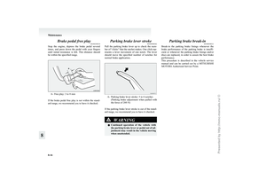
3. Slide a new wiper blade through the hook
(B) on the wiper arm. NOTE
l Do
not allow the wiper arm to fall onto the
window glass; it could damage the glass.
4. Firmly insert the retainer (C) into the groove (D) in the wiper blade. Refer to the illustration to ensure that the re-
tainers
are correctly aligned as you insert
them into the groove. NOTE
l If
a retainer is not supplied with the new wip-
er blade, use the retainer from the old blade. General maintenance
E01002700256
Fuel, engine coolant, oil and exhaust
gas leakage
Look
under the body of your vehicle to check for
fuel, engine coolant, oil and exhaust gas leaks. WARNING
l If
you see a suspicious fuel leak or if you
smell fuel, do not operate the vehicle; we
recommend you to call for assistance.
Exterior and interior lamp operation
Operate
the combination lamp switch to check that
all lamps are functioning properly.
If the lamps do not illuminate, the probable cause
is a blown fuse or defective lamp bulb. Check the
fuses first. If there is no blown fuses, check the
lamp bulbs.
For information regarding the inspection and re-
placement of the fuses and the lamp bulbs, refer to
“Fuses” on page 8-20 and “Replacement of lamp
bulbs” on page 8-25.
If the fuses and bulbs are all OK, we recommend
you to have your vehicle checked and repaired.
Meter, gauge and indicator/warning
lamps operation
Run the engine to check the operation of all meters,
gauges, and indicator/warning lamps.
If there is anything wrong, we recommend you to
have your vehicle inspected. Maintenance
8-18
8
Presented by http://mmc-manuals.ru/ \251
Page 228 of 273

Hinges and latches lubrication
Check
all latches and hinges, and lubricate if neces-
sary by first cleaning and then applying multipur-
pose grease. For cold and snowy weather
E01002800286
Ventilation slots
The
ventilation slots in front of the windscreen
should be kept clear of leaves or brushed clear after
a heavy snowfall, so that the operation of the heat-
ing and ventilation systems will not be impaired.
Weatherstripping
To prevent freezing of the weatherstripping on the
doors, bonnet, etc., they should be treated with sili-
cone grease.
Additional equipment
It is a good idea to carry a shovel or a short-han-
dled spade in the vehicle during the winter so that
you can clear away snow if you get stranded. A
small hand-brush for sweeping snow off the vehi-
cle and a plastic scraper for the windscreen and
rear window are also useful. Fusible links
E01002900173
The
fusible links will melt to prevent a fire if a
large current attempts to flow through certain elec-
trical systems.
In case of a melted fusible link, we recommend
you to have your vehicle inspected. Maintenance
8-19 8
Presented by http://mmc-manuals.ru/ \251
Page 229 of 273

Fuses
E01003001989
Fuse block location
To
prevent damage to the electrical system due to
shortcircuiting or overloading, each individual cir-
cuit is provided with a fuse.
There are fuse blocks in the passenger compart-
ment and in the engine compartment.
Passenger compartment
The fuse block in the passenger compartment is lo-
cated behind the fuse box lid (LHD vehicles) or the
personal box (RHD vehicles) in front of the driv-
er’s seat at the position shown in the illustration. Engine compartment
In
the engine compartment, the fuse block is loca-
ted as shown in the illustration.
Petrol-powered vehicles
Diesel-powered vehicles 1- Push the knob.
2-
Remove the cover.
Fuse load capacity
The fuse capacity and the name of the electrical sys-
tems protected by the fuses are indicated at the fuse
box lid (LHD vehicles) or the personal box (RHD
vehicles) and on the inside of the fuse block cover
for fuses located in the engine compartment.
Passenger compartment fuse location table
NOTE l Spare fuses are contained in the fuse box lid
(LHD vehicles) or the personal box lid
(RHD vehicles). Always use a fuse of the
same capacity for replacement. Maintenance
8-20
8LHD RHD
Presented by http://mmc-manuals.ru/ \251
Page 230 of 273
Passenger compartment fuse location (LHD)Passenger compartment fuse location (RHD)No. Symbol Electrical system Capaci-
ties
1 Ignition coil 10 A
2 Gauge 7.5 A
3 Reversing lamp 7.5 A
4 Cruise control 7.5 A
5 Relay 7.5 A
6 Heated door mirror 7.5 A
7 Windscreen wiper 30 A No. Symbol Electrical system Capaci-
ties
8 Engine control 7.5 A
9 Accessory socket 15 A
10 — ——
11 Outside rear-view
mirrors 7.5 A
12 Engine control 7.5 A
13 — ——
14 Rear window wiper 15 A
15 Central door locks 15 A
16 Rear fog lamp 10 A
17 — ——
18 — ——
19 Heater 30 A
20 Rear window demis-
ter 30 A
21 Sunroof 20 A
22 Heated seat 20 A
23 Rear air conditioning 20 A
24 Starter 10 A
25 — Spare fuse 30 A
26 — Spare fuse 20 A
27 — Spare fuse 30 A Maintenance
8-21 8
Presented by http://mmc-manuals.ru/ \251
Page 231 of 273

l
Some fuses may not be installed on your ve-
hicle, depending on the vehicle model or spec-
ifications.
l The table above shows the main equipment
corresponding to each fuse.
The fuse box does not contain spare 7.5 A,
10 A and 15 A fuses. If a fuse of one of these
capacities blows, replace it temporarily by
borrowing the one that matches from:
7.5 A: Outside rear-view mirrors
10 A: Radio (Engine compartment)
15 A: Accessory socket
Replace the borrowed fuse as soon as possible.
Engine compartment fuse location table
Engine compartment fuse location
Front No. Symbol Electrical system Capaci-
ties
1 —
—
—*1 Battery
60 A*2
2 Radiator fan motor
50 A
*1
40 A *2
3 Anti-lock brake sys-
tem 30 A
4 Anti-lock brake sys-
tem 40 A
5 Electric window sys-
tem 40 A
6 Front fog lamps 15 A
7 AC power supply
15 A*1 Accessory socket
Accessory socket
15 A*2
8 Horn 10 A
9 Engine control
20 A
*1
10 A *2
10 Air conditioning 10 A
*1 : Petrol-powered vehicles
*2 : Diesel-powered vehicles
*3 :
Vehicles without discharge headlamps: 55 W
(H1)
*4 : Vehicles with discharge headlamps: 35 W
(D2R) No. Symbol Electrical system Capaci-
ties
11 Stop lamps 15 A
12 Horn
15 A*1 Wiper de-icer
— —
—*2
13 Alternator
7.5 A*1 Starter
25 A*2
14 Hazard warning
flasher 10 A
15 Automatic transmis-
sion 20 A
*1
— —
—*2
16 Headlamp high-beam
(right) 10 A
17 Headlamp high-beam
(left) 10 A
18 Headlamp low beam
(right) 10 A
*3
20 A *4
19 Headlamp low beam
(left) 10 A
*3
20 A *4
*1 : Petrol-powered vehicles
*2 : Diesel-powered vehicles
*3 :
Vehicles without discharge headlamps: 55 W
(H1)
*4 : Vehicles with discharge headlamps: 35 W
(D2R) Maintenance
8-22
8
Presented by http://mmc-manuals.ru/ \251
Page 232 of 273

No. Symbol Electrical system Capaci-
ties
20 Tail lamp (right) 7.5 A
21 Tail lamp (left) 7.5 A
22 Back up 15 A
23 Radio 10 A
24 Fuel pump 15 A
25 Electric tailgate
—*1
— —
—*2
*1 : Petrol-powered vehicles
*2 : Diesel-powered vehicles
*3 :
Vehicles without discharge headlamps: 55 W
(H1)
*4 : Vehicles with discharge headlamps: 35 W
(D2R) Engine compartment fuse location (diesel-pow-
ered vehicles only)
Engine compartment fuse location
Front No. Symbol Electrical system Capaci-
ties
1 Condenser fan 30 A
2 Engine control 30 A
3 Control flap 10 A
4 Glow relay 10 A
5 Valve block 10 A
6 Immobilizer 7.5 A
7 Heating pipe 10 A l
Some
fuses may not be installed on your ve-
hicle, depending on the vehicle model or spec-
ifications.
l The table above shows the main equipment
corresponding to each fuse.
Identification of fuse Capacity Colour
7.5 A Brown
10 A Red
15 A Blue
20 A Yellow
25 A Transparent
30 A Green (fuse type)/
Pink (fusible link type)
40 A Green
50 A Red
60 A Yellow (fusible link type) Maintenance
8-23 8
Presented by http://mmc-manuals.ru/ \251