2010 JAGUAR XFR Engine
[x] Cancel search: EnginePage 1597 of 3039

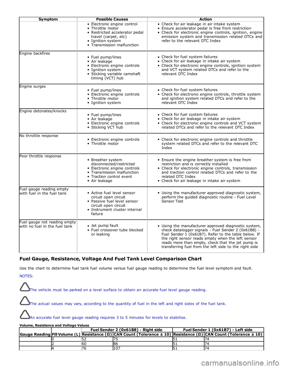
Symptom Possible Causes Action Electronic engine control
Throttle motor
Restricted accelerator pedal
travel (carpet, etc)
Ignition system
Transmission malfunction Check for air leakage in air intake system
Ensure accelerator pedal is free from restriction
Check for electronic engine controls, ignition, engine
emission system and transmission related DTCs and
refer to the relevant DTC Index Engine backfires
Fuel pump/lines
Air leakage
Electronic engine controls
Ignition system
Sticking variable camshaft
timing (VCT) hub
Check for fuel system failures
Check for air leakage in intake air system
Check for electronic engine controls, ignition system
and VCT system related DTCs and refer to the
relevant DTC Index Engine surges
Fuel pump/lines
Electronic engine controls
Throttle motor
Ignition system
Check for fuel system failures
Check for electronic engine controls, throttle system
and ignition system related DTCs and refer to the
relevant DTC Index Engine detonates/knocks
Fuel pump/lines
Air leakage
Electronic engine controls
Sticking VCT hub
Check for fuel system failures
Check for air leakage in intake air system
Check for electronic engine controls and VCT system
related DTCs and refer to the relevant DTC Index No throttle response
Electronic engine controls
Throttle motor
Check for electronic engine controls and throttle
system related DTCs and refer to the relevant DTC
Index Poor throttle response
Breather system
disconnected/restricted
Electronic engine controls
Transmission malfunction
Traction control event
Air leakage
Ensure the engine breather system is free from
restriction and is correctly installed
Check for electronic engine controls, transmission
and traction control related DTCs and refer to the
related DTC Index
Check for air leakage in intake air system Fuel gauge reading empty
with fuel in the fuel tank
Active fuel level sensor
circuit open circuit
Passive fuel level sensor
circuit open circuit
Instrument cluster internal
failure
Using the manufacturer approved diagnostic system,
perform the guided diagnostic routine - Fuel Level
Sensor Test Fuel gauge not reading empty
with no fuel in the fuel tank
Jet pump fault
Fuel crossover tube blocked
or leaking
Using the manufacturer approved diagnostic system,
check datalogger signals - Fuel Sender 2 (0x61B8) -
Fuel Sender 1 (0x61B7). Refer to the table below. If
the right sensor reads empty when the left sensor
reads more than empty, check that the jet pump is
transferring fuel from the left side to the right side Fuel Gauge, Resistance, Voltage And Fuel Tank Level Comparison Chart
Use the chart to determine fuel tank fuel volume versus fuel gauge reading to determine the fuel level symptom and fault.
NOTES:
The vehicle must be parked on a level surface to obtain an accurate fuel level gauge reading.
The actual values may vary, according to the quantity of fuel in the left and right sides of the fuel tank.
An accurate fuel level gauge reading requires 3 to 5 minutes for levels to stabilise.
Volume, Resistance and Voltage Values
Gauge Reading
Fill Volume (L) Fuel Sender 2 (0x61B8) - Right side Fuel Sender 1 (0x61B7) - Left side Resistance (Ω) CAN Count (Tolerance ± 10) Resistance (Ω) CAN Count (Tolerance ± 10) 0 52 75 51 74 2 60 86 51 74 4 76 107 51 74
Page 1598 of 3039

Resistance (Ω) CAN Count (Tolerance ± 10) Resistance (Ω) CAN Count (Tolerance ± 10) 6 86 119 51 74 8 121 160 51 74 10 151 191 51 74 Empty 12 183 223 51 74 14 205 244 51 74 16 242 276 51 74 18 283 308 51 74 20 327 340 51 74 ¼ 22 358 361 51 74 24 408 392 51 74 26 445 414 51 74 28 446 436 51 74 30 446 436 51 74 32 446 436 59 85 34 446 436 75 106 36 445 425 101 148 38 486 436 170 159 40 486 446 140 170 ½ 42 486 446 160 201 44 460 425 192 223 46 486 446 204 243 48 552 457 204 243 50 626 489 204 243 52 654 521 228 254 54 654 521 241 275 56 654 521 254 286 ¾ 58 654 521 281 307 60 684 531 296 318 62 707 531 326 339 64 727 541 357 350 66 737 562 373 370 Full 67 803 563 407 391 Maximum Fill Maximum Fill 911 594 425 402 DTC Index
For a list of Diagnostic Trouble Codes (DTCs) that could be logged in the Engine Control Module (ECM), please refer to Section
303-14. REFER to:
Electronic Engine Controls (303-14C Electronic Engine Controls - V8 5.0L Petrol, Diagnosis and Testing), Electronic Engine Controls (303-14D Electronic Engine Controls - V8 S/C 5.0L Petrol, Diagnosis and Testing).
Page 1614 of 3039

Published: 31-Oct-2013
Fuel Tank and Lines - V8 5.0L Petrol/V8 S/C 5.0L Petrol - Fuel Rail High-Pressure Fuel Pump Supply Line
Removal and Installation
Removal
NOTES:
Some variation in the illustrations may occur, but the essential information is always correct.
Some illustrations may show the engine removed for clarity.
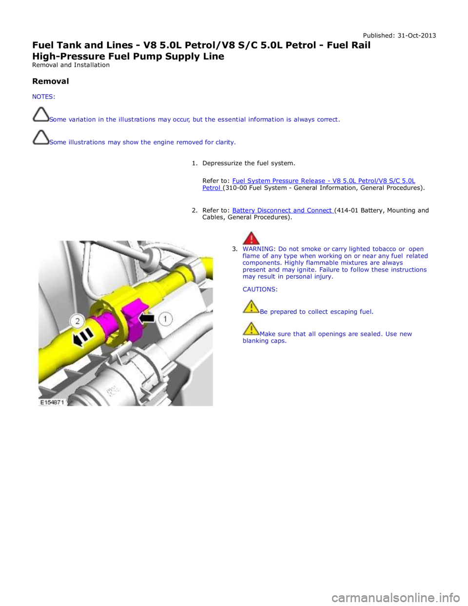
1. Depressurize the fuel system.
Refer to: Fuel System Pressure Release - V8 5.0L Petrol/V8 S/C 5.0L Petrol (310-00 Fuel System - General Information, General Procedures).
2. Refer to: Battery Disconnect and Connect (414-01 Battery, Mounting and Cables, General Procedures).
3. WARNING: Do not smoke or carry lighted tobacco or open
flame of any type when working on or near any fuel related
components. Highly flammable mixtures are always
present and may ignite. Failure to follow these instructions
may result in personal injury.
CAUTIONS:
Be prepared to collect escaping fuel.
Make sure that all openings are sealed. Use new
blanking caps.
Page 1631 of 3039

Acceleration Control - Acceleration Control
Diagnosis and Testing
Principles of Operation Published: 11-May-2011
For a detailed description of the acceleration controls, refer to the relevant Description and Operation sections in the workshop
manual. REFER to: Acceleration Control (310-02, Description and Operation).
Inspection and Verification
CAUTION: Diagnosis by substitution from a donor vehicle is NOT acceptable. Substitution of control modules does not
guarantee confirmation of a fault, and may also cause additional faults in the vehicle being tested and/or the donor vehicle.
1. Verify the customer concern.
2. Visually inspect for obvious signs of damage and system integrity.
Visual Inspection
Mechanical Electrical
Accelerator pedal
Throttle body
Fuses
Wiring harness
Electrical connector(s)
Sensor(s)
Engine control module (ECM)
3. If an obvious cause for an observed or reported concern is found, correct the cause (if possible) before proceeding to
the next step.
4. If the cause is not visually evident check for Diagnostic Trouble Codes (DTCs) and refer to the DTC Index.
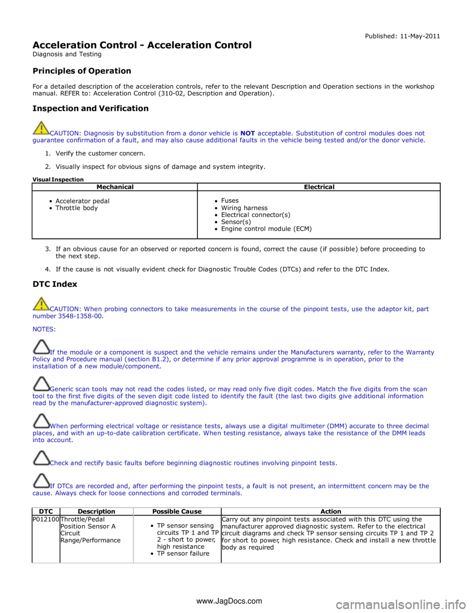
DTC Index
CAUTION: When probing connectors to take measurements in the course of the pinpoint tests, use the adaptor kit, part
number 3548-1358-00.
NOTES:
If the module or a component is suspect and the vehicle remains under the Manufacturers warranty, refer to the Warranty
Policy and Procedure manual (section B1.2), or determine if any prior approval programme is in operation, prior to the
installation of a new module/component.
Generic scan tools may not read the codes listed, or may read only five digit codes. Match the five digits from the scan
tool to the first five digits of the seven digit code listed to identify the fault (the last two digits give additional information
read by the manufacturer-approved diagnostic system).
When performing electrical voltage or resistance tests, always use a digital multimeter (DMM) accurate to three decimal
places, and with an up-to-date calibration certificate. When testing resistance, always take the resistance of the DMM leads
into account.
Check and rectify basic faults before beginning diagnostic routines involving pinpoint tests.
If DTCs are recorded and, after performing the pinpoint tests, a fault is not present, an intermittent concern may be the
cause. Always check for loose connections and corroded terminals.
DTC Description Possible Cause Action P012100 Throttle/Pedal
Position Sensor A
Circuit
Range/Performance
TP sensor sensing
circuits TP 1 and TP
2 - short to power,
high resistance
TP sensor failure Carry out any pinpoint tests associated with this DTC using the
manufacturer approved diagnostic system. Refer to the electrical
circuit diagrams and check TP sensor sensing circuits TP 1 and TP 2
for short to power, high resistance. Check and install a new throttle
body as required www.JagDocs.com
Page 1633 of 3039

DTC Description Possible Cause Action ECM fault
P210500 Throttle Actuator
Control System -
Forced Engine
Shutdown
Throttle MIL
request due to fuel
cut Carry out any pinpoint tests associated with this DTC using the
manufacturer approved diagnostic system P211800 Throttle Actuator
Control Motor Current
Range/Performance
Throttle motor
control circuit -
short to ground,
power, high
resistance Carry out any pinpoint tests associated with this DTC using the
manufacturer approved diagnostic system. Refer to the electrical
circuit diagrams and check throttle motor control circuit for short to
ground, power, high resistance P211900 Throttle Actuator
Control Throttle Body
Range/Performance
Throttle spring
faulty Carry out any pinpoint tests associated with this DTC using the
manufacturer approved diagnostic system. Suspect throttle body
faulty. Check and install a new throttle body as required, refer to
the new module/component installation note at top of DTC Index P212200 Throttle/Pedal
Position Sensor/Switch
D Circuit Low
APP sensor circuit 2
- low input Carry out any pinpoint tests associated with this DTC using the
manufacturer approved diagnostic system. Refer to the electrical
circuit diagrams and check APP sensor circuit 2 for short to ground, open circuit P212216 Throttle/Pedal
Position Sensor/Switch
D Circuit Low Input
Accelerator pedal
position (APP)
sensor circuit 1 -
short to ground,
power
Accelerator pedal
position (APP)
sensor failure Carry out any pinpoint tests associated with this DTC using the
manufacturer approved diagnostic system. Refer to electrical circuit
diagrams and check accelerator pedal position (APP) sensor circuit 1
for short to ground, power. Set ignition status to 'ON' engine 'OFF'
check and record 'Pedal value sensor 1' datalogger signal. With
pedal in idle position, value of signal should be approximately 0%,
if not suspect the pedal position sensor, check and install a new
sensor as required P212300 Throttle/Pedal
Position Sensor/Switch
D Circuit High
APP sensor circuit 2
- high input Carry out any pinpoint tests associated with this DTC using the
manufacturer approved diagnostic system. Refer to the electrical
circuit diagrams and check APP sensor circuit 2 for short to power P212317 Throttle/Pedal
Position Sensor/Switch
D Circuit High Input
Accelerator pedal
position (APP)
sensor circuit 1 -
short to power
Accelerator pedal
position (APP)
sensor failure Carry out any pinpoint tests associated with this DTC using the
manufacturer approved diagnostic system. Refer to electrical circuit
diagrams and check accelerator pedal position (APP) sensor circuit 1
for short to ground, power. Set ignition status to 'ON' engine 'OFF'
check and record 'Pedal value sensor 1' datalogger signal. With
pedal in fully depressed position, value of signal should be
approximately 99%, if not suspect the pedal position sensor, check
and install a new sensor as required P212716 Throttle/Pedal
Position Sensor/Switch
E Circuit Low Input
Accelerator pedal
position (APP)
sensor circuit 2 -
short to ground,
high resistance
Accelerator pedal
position (APP)
sensor failure Carry out any pinpoint tests associated with this DTC using the
manufacturer approved diagnostic system. Refer to electrical circuit
diagrams and check accelerator pedal position (APP) sensor circuit 2
for short to ground, power. Set ignition status to 'ON' engine 'OFF'
check and record 'Pedal value sensor 2' datalogger signal. With
pedal in idle position, value of signal should be approximately 0%,
if not suspect the pedal position sensor, check and install a new
sensor as required P212817 Throttle/Pedal
Position Sensor/Switch
E Circuit High Input
Accelerator pedal
position (APP)
sensor circuit 2 -
short to power
Accelerator pedal
position (APP)
sensor failure Carry out any pinpoint tests associated with this DTC using the
manufacturer approved diagnostic system. Refer to electrical circuit
diagrams and check accelerator pedal position (APP) sensor circuit 2
for short to ground, power. Set ignition status to 'ON' engine 'OFF'
check and record 'Pedal value sensor 2' datalogger signal. With
pedal in fully depressed position, value of signal should be
approximately 99%, if not suspect the pedal position sensor, check
and install a new sensor as required P213528 Throttle/Pedal
Position Sensor/Switch
A/B Voltage
Correlation
APP sensor circuit 1
and 2 range
performance -
sub-processor Carry out any pinpoint tests associated with this DTC using the
manufacturer approved diagnostic system. Refer to the electrical
circuit diagrams and check APP sensor circuits 1 and 2 for short to
ground, power and high resistance. Clear the DTCs and retest. If
the code remains, replace the APP sensor P213529 Throttle/Pedal
Position Sensor/Switch
A/B Voltage
Correlation
APP sensor -
excessive difference
between
raw values of circuit
1 and 2 -
sub-processor Carry out any pinpoint tests associated with this DTC using the
manufacturer approved diagnostic system. Refer to the electrical
circuit diagrams and check APP sensor circuits 1 and 2 for short,
open circuit
Page 1634 of 3039

DTC Description Possible Cause Action P213562 Throttle/Pedal
Position Sensor/Switch
A/B Voltage
Correlation
APP sensor circuit 1
and 2 range
performance -
sub-processor Carry out any pinpoint tests associated with this DTC using the
manufacturer approved diagnostic system. Refer to the electrical
circuit diagrams and check APP sensor circuits 1 and 2 for short to
ground, power and high resistance. Clear the DTCs and retest. If
the code remains, replace the APP sensor P213564 Throttle/Pedal
Position Sensor/Switch
A/B Voltage
Correlation
APP sensor circuit 1
and 2 range
performance Carry out any pinpoint tests associated with this DTC using the
manufacturer approved diagnostic system. Refer to the electrical
circuit diagrams and check APP sensor circuits 1 and 2 for short,
open circuit P213862 Throttle/Pedal
Position Sensor/Switch
D/E Voltage
Correlation
Pedal value
difference between
channel 1 and
channel 2 greater
than a threshold Carry out any pinpoint tests associated with this DTC using the
manufacturer approved diagnostic system. Refer to electrical circuit
diagrams and check accelerator pedal position (APP) sensor circuit 1
and 2 for short to ground, power. Set ignition status to 'ON' engine
'OFF' check and record 'Pedal value sensor 1' and 'Pedal value
sensor 2' datalogger signal. With pedal in fully depressed position,
value of signals should be approximately 99%, with pedal in idle
position, value of signals should be approximately 0%, if not
suspect the pedal position sensor, check and install a new sensor
as required P213864 Throttle/Pedal
Position Sensor/Switch
D/E Voltage
Correlation
Gradient on one
channel without
gradient on the
other Carry out any pinpoint tests associated with this DTC using the
manufacturer approved diagnostic system. Refer to electrical circuit
diagrams and check accelerator pedal position (APP) sensor circuit 1
and 2 for short to ground, power. Set ignition status to 'ON' engine
'OFF' check and record 'Pedal value sensor 1' and 'Pedal value
sensor 2' datalogger signal. With pedal in fully depressed position,
value of signals should be approximately 99%, with pedal in idle
position, value of signals should be approximately 0%, if not
suspect the pedal position sensor, check and install a new sensor
as required
Page 1637 of 3039

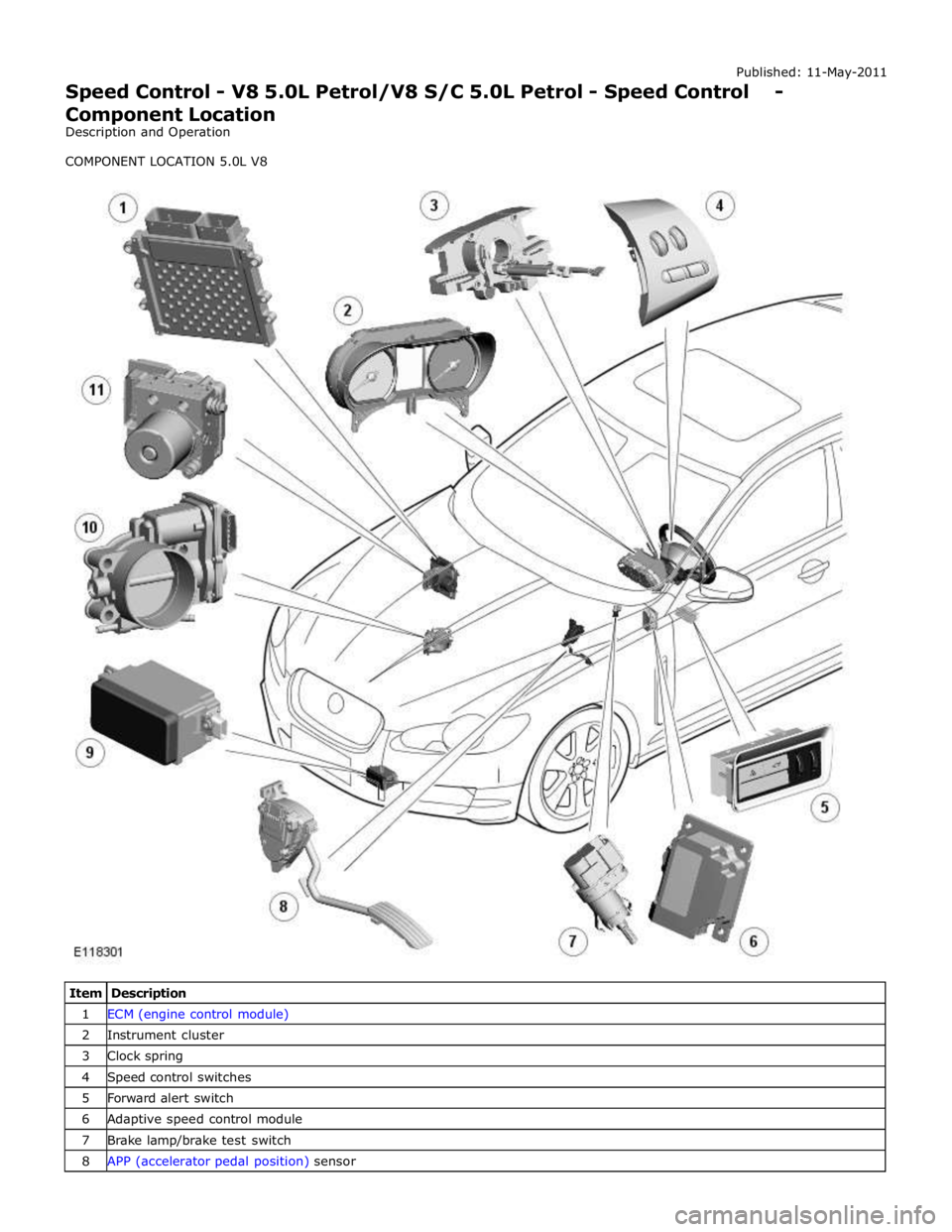
1 ECM (engine control module) 2 Instrument cluster 3 Clock spring 4 Speed control switches 5 Forward alert switch 6 Adaptive speed control module 7 Brake lamp/brake test switch 8 APP (accelerator pedal position) sensor
Page 1639 of 3039

Published: 11-May-2011
Speed Control - V8 5.0L Petrol/V8 S/C 5.0L Petrol - Speed Control - Overview
Description and Operation
OVERVIEW
Speed Control
The speed control system is integrated with the engine management system and uses fueling intervention to automatically
maintain a set vehicle speed. Once engaged, the system can also be used to accelerate the vehicle without using the
accelerator pedal.
The speed control system comprises the following components:
On/Off/Suspend switch
'+' and '-' (set/accelerate and decelerate) steering wheel switches
Resume switch
Clock spring
Speed control warning indicator.
Adaptive Speed Control
The adaptive speed control system uses a forward looking radar sensor to scan the road ahead, looking for objects that are
moving at a different rate to itself. When a target is identified the adaptive speed control system will monitor the time gap
between it and the target vehicle. When that gap falls below a set driver selected level the adaptive speed control system will
intervene slowing the vehicle by backing off the throttle and/ or applying the brakes, until the correct gap is attained.
The adaptive speed control system comprises the following components:
Adaptive speed control sensor
Adaptive speed control module
Steering wheel control switches
ECM (engine control module)
Electric throttle actuator
ABS (anti-lock brake system) module and pump
Adaptive speed control warning indicator (in the instrument cluster).