Page 2821 of 3039

Lighting, Removal and Installation).
7. Remove the condenser core.
For additional information, refer to: Condenser Core - 2.7L Diesel
(412-03, Removal and Installation) /
Condenser Core - V6 3.0L Petrol (412-03 Air Conditioning, Removal and Installation) /
Condenser Core - 4.2L, Vehicles Without: Supercharger (412-03, Removal
and Installation) /
Condenser Core - 4.2L, Vehicles With: Supercharger (412-03, Removal
and Installation).
8. Remove the radiator.
For additional information, refer to: Radiator (303-03A, Removal and
Installation) /
Radiator (303-03B Engine Cooling - V6 3.0L Petrol, Removal and Installation) /
Radiator - Vehicles With: Supercharger (303-03C, Removal and
Installation) /
Radiator - Vehicles Without: Supercharger (303-03C, Removal and
Installation).
9. Remove the both hood latch panel braces.
10. Remove the cooling fan upper shroud.
11. Remove both crash sensors.
For additional information, refer to: Crash Sensor (501-20B Supplemental Restraint System, Removal and Installation).
12. Remove the both hood latches.
13. Remove the hood safety hook guide.
14. Remove both hood latch panel buffers.
15. Release and lay aside the hood latch panel wiring harness.
16. Remove the old panel.
Page 2982 of 3039

12.
13.
14.
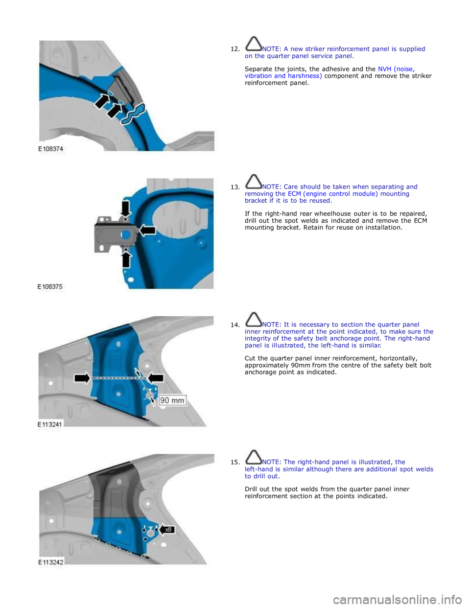
15. NOTE: A new striker reinforcement panel is supplied
on the quarter panel service panel.
Separate the joints, the adhesive and the NVH (noise,
vibration and harshness) component and remove the striker
reinforcement panel.
NOTE: Care should be taken when separating and
removing the ECM (engine control module) mounting
bracket if it is to be reused.
If the right-hand rear wheelhouse outer is to be repaired,
drill out the spot welds as indicated and remove the ECM
mounting bracket. Retain for reuse on installation.
NOTE: It is necessary to section the quarter panel
inner reinforcement at the point indicated, to make sure the
integrity of the safety belt anchorage point. The right-hand
panel is illustrated, the left-hand is similar.
Cut the quarter panel inner reinforcement, horizontally,
approximately 90mm from the centre of the safety belt bolt
anchorage point as indicated.
NOTE: The right-hand panel is illustrated, the
left-hand is similar although there are additional spot welds
to drill out.
Drill out the spot welds from the quarter panel inner
reinforcement section at the points indicated.
Page 3013 of 3039
Front lower arm to front subframe retaining nut and bolt 175 129 - Rear lower arm to front subframe retaining nut and bolt 175 129 - Engine mount lower retaining nut 63 46 - Steering gear retaining bolts 100 74 - Front Shock absorber and spring assembly retaining bolt 175 129 - Front subframe to body front retaining bolt Stage 1 100 73 - Stage 2 270° 270° - Front subframe to body rear retaining bolt Stage 1 80 59 - Stage 2 240° 240° - Front Stabilizer bar link retaining nuts 43 31 - Front Stabilizer bar link retaining bolts 55 41 - Rear Shock absorber and spring assembly retaining bolt 133 98 - Rear subframe reinforcement plate retaining bolts 47 35 - Rear subframe to body retaining bolts Stage 1 80 59 - Stage 2 240° 240° -
Page 3014 of 3039
Published: 31-Jul-2013
Uni-Body, Subframe and Mounting System - Front Subframe V8 5.0L Petrol/V8 S/C 5.0L Petrol
Removal and Installation
Special Tool(s)
303-021
Engine support bracket
303-1436
Engine Lifting Bracket Front
502-005
Alignment Bolts, Subframe General Equipment
Removal
NOTE: Some variation in the illustrations may occur, but the essential information is always correct.
1. Refer to: Battery Disconnect and Connect (414-01 Battery, Mounting and Cables, General Procedures).
2. WARNING: Make sure to support the vehicle with axle stands.
Raise and support the vehicle.
3. Refer to: Radiator Splash Shield (501-02 Front End Body Panels, Removal and Installation). 4. Refer to: Air Deflector (501-02 Front End Body Panels, Removal and Installation). 5. Refer to: Engine Cover - V8 5.0L Petrol/V8 S/C 5.0L Petrol (501-05 Interior Trim and Ornamentation, Removal and Installation). Powertrain Jack
Page 3015 of 3039
6. Secure the radiator assembly.
7.
Special Tool(s): 303-1436 Torque: 40 Nm
8. CAUTIONS:
Support the engine on a jack. The angle may need to be adjusted during this procedure.
Make sure to protect the paintwork.
Special Tool(s): 303-021 Special Tool(s): 303-1436
Page 3031 of 3039
27. Release the radiator assembly.
28.
Refer to: Engine Cover - V8 5.0L Petrol/V8 S/C 5.0L Petrol (501-05 Interior Trim and Ornamentation, Removal and Installation).
29. Refer to: Air Deflector (501-02 Front End Body Panels, Removal and Installation). 30. Refer to: Radiator Splash Shield (501-02 Front End Body Panels, Removal and Installation). 31. Refer to: Battery Disconnect and Connect (414-01 Battery, Mounting and Cables, General Procedures).
32.
Refer to: Camber and Caster Adjustment (204-00 Suspension System - General Information, General Procedures).
Page 3038 of 3039
Reciever-bush
204-475
Replacer-bush
204-474
Remover bush
204-473
Remover support-bush
204-472
Removal
Vehicles with 3.0L diesel engine
1. For additional information, refer to: Rear Subframe - TDV6 3.0L Diesel (502-00 Uni-Body, Subframe and Mounting System, Removal and
Installation).
Vehicles with 5.0L
2. For additional information, refer to: Rear Subframe - V8 5.0L Petrol/V8 S/C 5.0L Petrol (502-00 Uni-Body, Subframe and Mounting System, Removal and Installation).
Page 3039 of 3039
All vehicles
3. NOTE: Note the orientation of the bushing before
removal.
Installation
All vehicles
1. NOTE: Make sure the bushing is correctly orientated.
Vehicles with 5.0L
2. For additional information, refer to: Rear Subframe - V8 5.0L Petrol/V8 S/C 5.0L Petrol (502-00 Uni-Body, Subframe and Mounting System, Removal and Installation).
Vehicles with 3.0L diesel engine
3. For additional information, refer to: Rear Subframe - TDV6 3.0L Diesel (502-00 Uni-Body, Subframe and Mounting System, Removal and
Installation).
www.JagDocs.com