2010 JAGUAR XFR Engine
[x] Cancel search: EnginePage 2754 of 3039
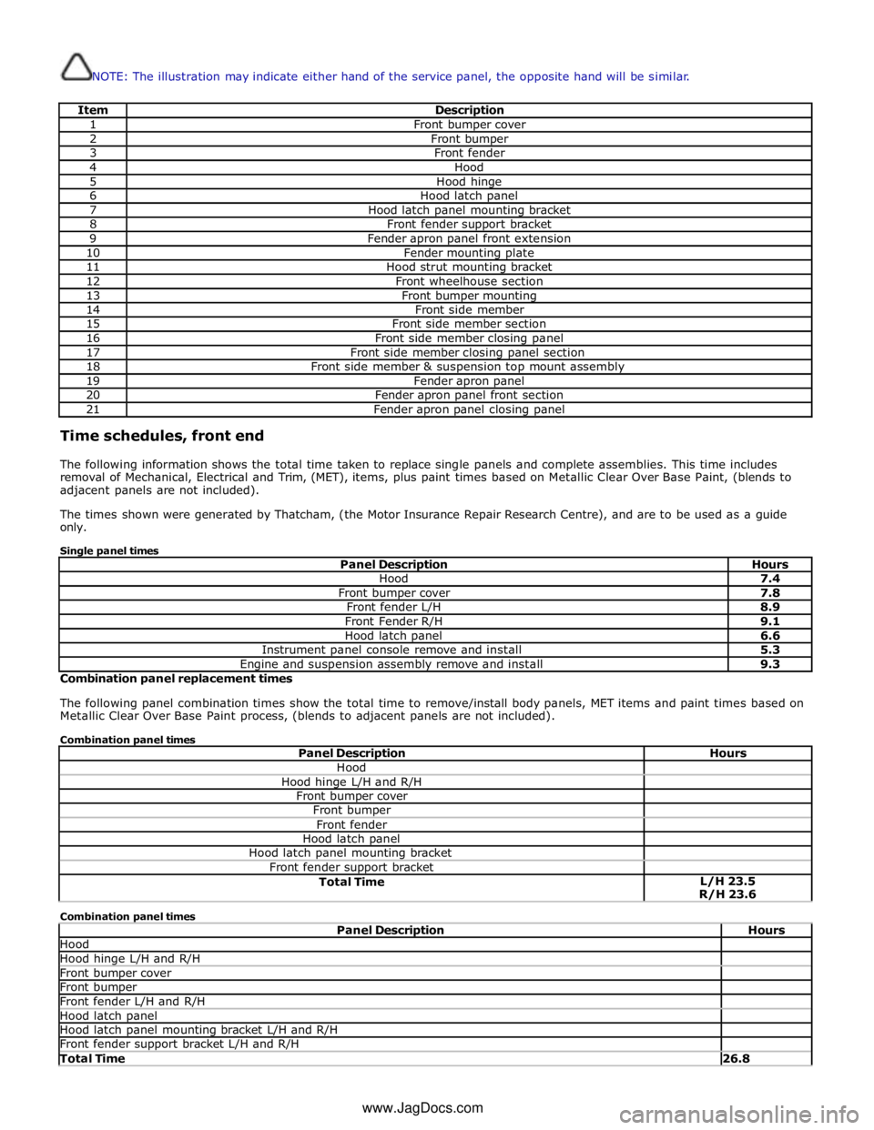
NOTE: The illustration may indicate either hand of the service panel, the opposite hand will be similar.
Item Description 1 Front bumper cover 2 Front bumper 3 Front fender 4 Hood 5 Hood hinge 6 Hood latch panel 7 Hood latch panel mounting bracket 8 Front fender support bracket 9 Fender apron panel front extension 10 Fender mounting plate 11 Hood strut mounting bracket 12 Front wheelhouse section 13 Front bumper mounting 14 Front side member 15 Front side member section 16 Front side member closing panel 17 Front side member closing panel section 18 Front side member & suspension top mount assembly 19 Fender apron panel 20 Fender apron panel front section 21 Fender apron panel closing panel Time schedules, front end
The following information shows the total time taken to replace single panels and complete assemblies. This time includes
removal of Mechanical, Electrical and Trim, (MET), items, plus paint times based on Metallic Clear Over Base Paint, (blends to
adjacent panels are not included).
The times shown were generated by Thatcham, (the Motor Insurance Repair Research Centre), and are to be used as a guide
only.
Single panel times
Panel Description Hours Hood 7.4 Front bumper cover 7.8 Front fender L/H 8.9 Front Fender R/H 9.1 Hood latch panel 6.6 Instrument panel console remove and install 5.3 Engine and suspension assembly remove and install 9.3 Combination panel replacement times
The following panel combination times show the total time to remove/install body panels, MET items and paint times based on
Metallic Clear Over Base Paint process, (blends to adjacent panels are not included).
Combination panel times
Panel Description Hours Hood Hood hinge L/H and R/H Front bumper cover Front bumper Front fender Hood latch panel Hood latch panel mounting bracket Front fender support bracket Total Time L/H 23.5
R/H 23.6 Combination panel times
Panel Description Hours Hood Hood hinge L/H and R/H Front bumper cover Front bumper Front fender L/H and R/H Hood latch panel Hood latch panel mounting bracket L/H and R/H Front fender support bracket L/H and R/H Total Time 26.8 www.JagDocs.com
Page 2755 of 3039
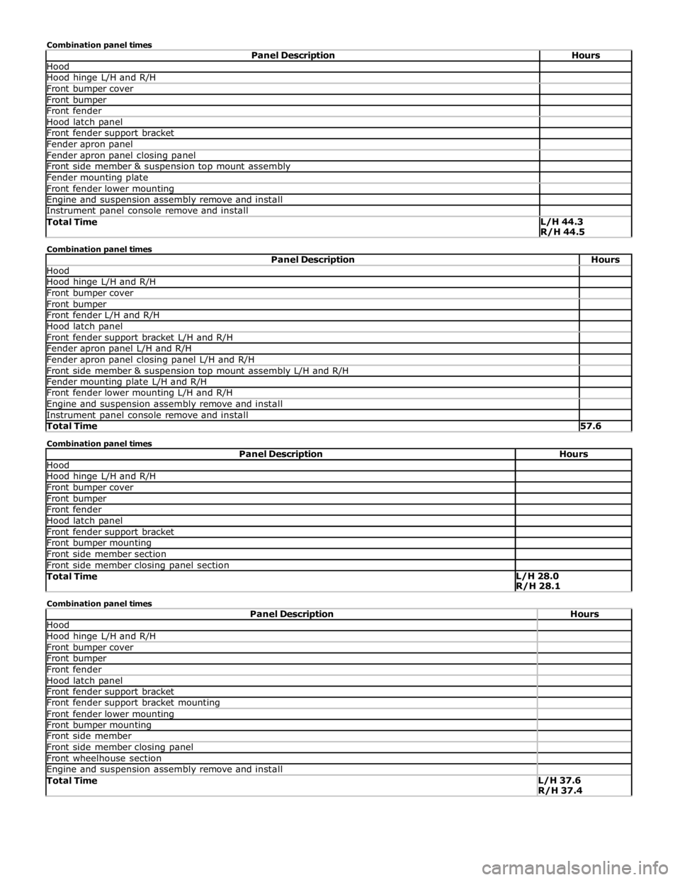
Hood Hood hinge L/H and R/H Front bumper cover Front bumper Front fender Hood latch panel Front fender support bracket Fender apron panel Fender apron panel closing panel Front side member & suspension top mount assembly Fender mounting plate Front fender lower mounting Engine and suspension assembly remove and install Instrument panel console remove and install Total Time L/H 44.3
R/H 44.5 Combination panel times
Panel Description Hours Hood Hood hinge L/H and R/H Front bumper cover Front bumper Front fender L/H and R/H Hood latch panel Front fender support bracket L/H and R/H Fender apron panel L/H and R/H Fender apron panel closing panel L/H and R/H Front side member & suspension top mount assembly L/H and R/H Fender mounting plate L/H and R/H Front fender lower mounting L/H and R/H Engine and suspension assembly remove and install Instrument panel console remove and install Total Time 57.6 Combination panel times
Panel Description Hours Hood Hood hinge L/H and R/H Front bumper cover Front bumper Front fender Hood latch panel Front fender support bracket Front bumper mounting Front side member section Front side member closing panel section Total Time L/H 28.0
R/H 28.1 Combination panel times
Panel Description Hours Hood Hood hinge L/H and R/H Front bumper cover Front bumper Front fender Hood latch panel Front fender support bracket Front fender support bracket mounting Front fender lower mounting Front bumper mounting Front side member Front side member closing panel Front wheelhouse section Engine and suspension assembly remove and install Total Time L/H 37.6
R/H 37.4
Page 2759 of 3039
Front End Sheet Metal Repairs - Fender Apron Panel
Removal and Installation
Removal Published: 11-May-2011
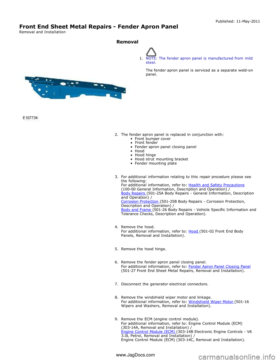
1. NOTE: The fender apron panel is manufactured from mild
steel.
The fender apron panel is serviced as a separate weld-on
panel.
2. The fender apron panel is replaced in conjunction with:
Front bumper cover
Front fender
Fender apron panel closing panel
Hood
Hood hinge
Hood strut mounting bracket
Fender mounting plate
3. For additional information relating to this repair procedure please see
the following:
For additional information, refer to: Health and Safety Precautions (100-00 General Information, Description and Operation) /
Body Repairs (501-25A Body Repairs - General Information, Description and Operation) /
Corrosion Protection (501-25B Body Repairs - Corrosion Protection, Description and Operation) /
Body and Frame (501-26 Body Repairs - Vehicle Specific Information and Tolerance Checks, Description and Operation).
4. Remove the hood.
For additional information, refer to: Hood (501-02 Front End Body Panels, Removal and Installation).
5. Remove the hood hinge.
6. Remove the fender apron panel closing panel.
For additional information, refer to: Fender Apron Panel Closing Panel (501-27 Front End Sheet Metal Repairs, Removal and Installation).
7. Disconnect the generator electrical connectors.
8. Remove the windshield wiper motor and linkage.
For additional information, refer to: Windshield Wiper Motor (501-16 Wipers and Washers, Removal and Installation).
9. Remove the ECM (engine control module).
For additional information, refer to: Engine Control Module (ECM)
(303-14A, Removal and Installation) /
Engine Control Module (ECM) (303-14B Electronic Engine Controls - V6 3.0L Petrol, Removal and Installation) /
Engine Control Module (ECM) (303-14C, Removal and Installation). www.JagDocs.com
Page 2784 of 3039
Front End Sheet Metal Repairs - Front Side Member
Removal and Installation
Removal Published: 11-May-2011
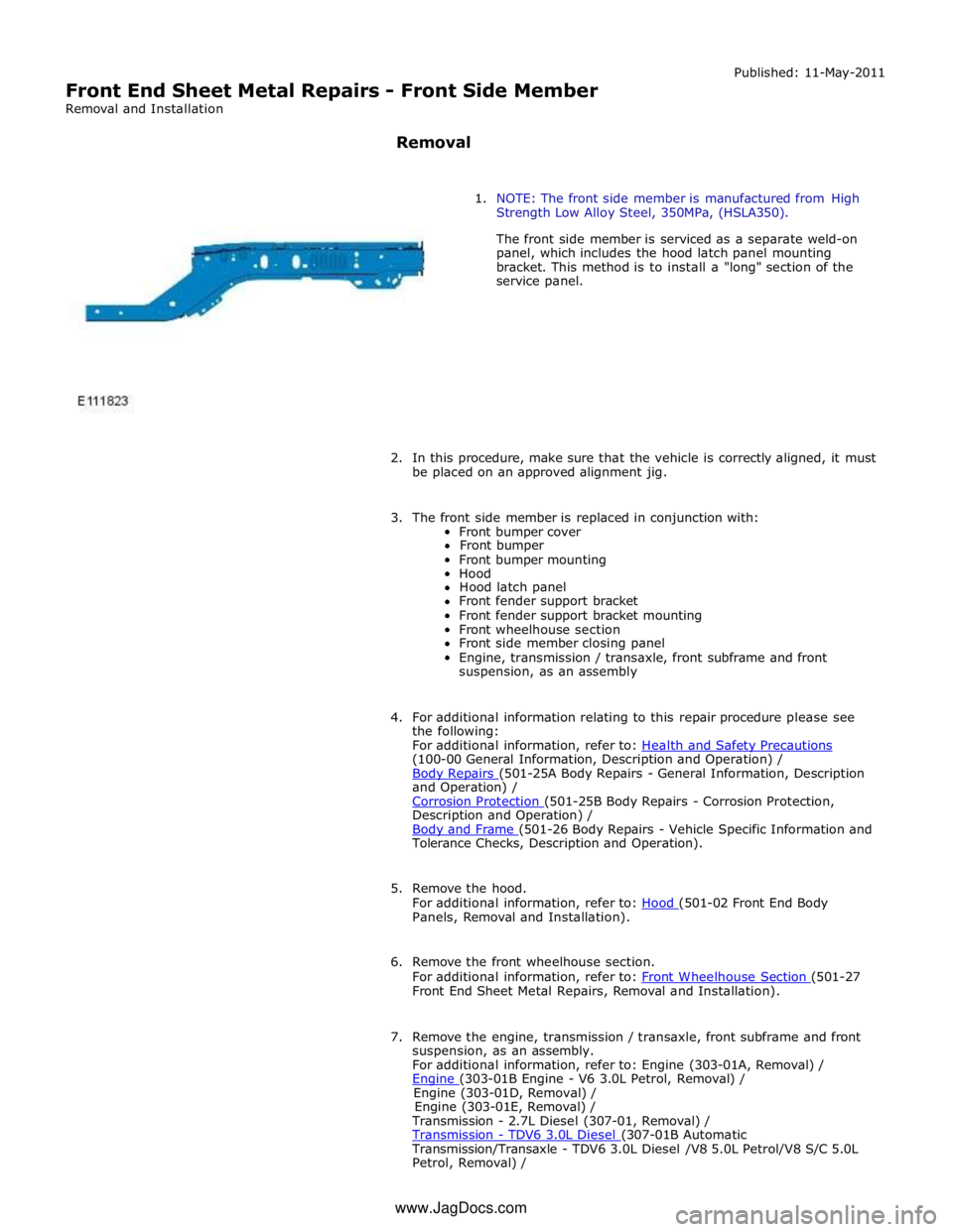
1. NOTE: The front side member is manufactured from High
Strength Low Alloy Steel, 350MPa, (HSLA350).
The front side member is serviced as a separate weld-on
panel, which includes the hood latch panel mounting
bracket. This method is to install a "long" section of the
service panel.
2. In this procedure, make sure that the vehicle is correctly aligned, it must
be placed on an approved alignment jig.
3. The front side member is replaced in conjunction with:
Front bumper cover
Front bumper
Front bumper mounting
Hood
Hood latch panel
Front fender support bracket
Front fender support bracket mounting
Front wheelhouse section
Front side member closing panel
Engine, transmission / transaxle, front subframe and front
suspension, as an assembly
4. For additional information relating to this repair procedure please see
the following:
For additional information, refer to: Health and Safety Precautions (100-00 General Information, Description and Operation) /
Body Repairs (501-25A Body Repairs - General Information, Description and Operation) /
Corrosion Protection (501-25B Body Repairs - Corrosion Protection, Description and Operation) /
Body and Frame (501-26 Body Repairs - Vehicle Specific Information and Tolerance Checks, Description and Operation).
5. Remove the hood.
For additional information, refer to: Hood (501-02 Front End Body Panels, Removal and Installation).
6. Remove the front wheelhouse section.
For additional information, refer to: Front Wheelhouse Section (501-27 Front End Sheet Metal Repairs, Removal and Installation).
7. Remove the engine, transmission / transaxle, front subframe and front
suspension, as an assembly.
For additional information, refer to: Engine (303-01A, Removal) /
Engine (303-01B Engine - V6 3.0L Petrol, Removal) / Engine (303-01D, Removal) /
Engine (303-01E, Removal) /
Transmission - 2.7L Diesel (307-01, Removal) /
Transmission - TDV6 3.0L Diesel (307-01B Automatic Transmission/Transaxle - TDV6 3.0L Diesel /V8 5.0L Petrol/V8 S/C 5.0L
Petrol, Removal) / www.JagDocs.com
Page 2797 of 3039
(100-00 General Information, Description and Operation) /
Body Repairs (501-25A Body Repairs - General Information, Description and Operation) /
Corrosion Protection (501-25B Body Repairs - Corrosion Protection, Description and Operation) /
Body and Frame (501-26 Body Repairs - Vehicle Specific Information and Tolerance Checks, Description and Operation).
5. Remove the fender apron panel front extension.
For additional information, refer to: Fender Apron Panel Front Extension (501-27 Front End Sheet Metal Repairs, Removal and Installation).
6. Remove the front fender support bracket.
For additional information, refer to: Front Fender Support Bracket (501-27 Front End Sheet Metal Repairs, Removal and Installation).
7. Remove the fender apron panel.
For additional information, refer to: Fender Apron Panel (501-27 Front End Sheet Metal Repairs, Removal and Installation).
8. Remove the engine, transmission / transaxle, front subframe and front
suspension, as an assembly.
For additional information, refer to: Engine (303-01A, Removal) /
Engine (303-01B Engine - V6 3.0L Petrol, Removal) / Engine (303-01D, Removal) /
Engine (303-01E, Removal) /
Transmission - 2.7L Diesel (307-01, Removal) /
Transmission - TDV6 3.0L Diesel (307-01B Automatic Transmission/Transaxle - TDV6 3.0L Diesel /V8 5.0L Petrol/V8 S/C 5.0L
Petrol, Removal) /
Transmission (307-01A Automatic Transmission/Transaxle - V6 3.0L Petrol, Removal) /
Transmission - 4.2L (307-01, Removal) /
Transmission - V8 5.0L Petrol/V8 S/C 5.0L Petrol (307-01B Automatic Transmission/Transaxle - TDV6 3.0L Diesel /V8 5.0L Petrol/V8 S/C 5.0L
Petrol, Removal) /
Front Shock Absorber (204-01 Front Suspension, Removal and Installation) /
Front Subframe - 2.7L Diesel (502-00, Removal and Installation) /
Front Subframe - V6 3.0L Petrol (502-00 Uni-Body, Subframe and Mounting System, Removal and Installation) /
Front Subframe - 4.2L, Vehicles Without: Supercharger (502-00, Removal
and Installation) /
Front Subframe - 4.2L, Vehicles With: Supercharger (502-00, Removal
and Installation).
9. Remove the pedestrian protection hood actuator.
For additional information, refer to: Pedestrian Protection Hood Actuator LH (501-20C Pedestrian Protection System, Removal and Installation) / Pedestrian Protection Hood Actuator RH (501-20C Pedestrian Protection System, Removal and Installation).
10. If the drivers side front side member and suspension top mount is to be
repaired, remove the brake master cylinder and reservoir.
For additional information, refer to: Brake Master Cylinder (206-06 Hydraulic Brake Actuation, Removal and Installation) /
Brake Fluid Reservoir (206-06 Hydraulic Brake Actuation, Removal and Installation).
11. If the drivers side front side member and suspension top mount is to be
repaired, remove the brake booster.
Page 2798 of 3039
Actuation, Removal and Installation).
12. Remove the left-hand and right-hand front seats.
For additional information, refer to: Front Seat (501-10 Seating, Removal and Installation).
13. Remove the heater core and evaporator core housing.
For additional information, refer to: Heater Core and Evaporator Core Housing (412-01 Climate Control, Removal and Installation).
14. Remove the front safety belt retractor.
For additional information, refer to: Front Safety Belt Retractor (501-20A Safety Belt System, Removal and Installation).
15. Remove the B-pillar side impact sensor.
For additional information, refer to: B-Pillar Side Impact Sensor (501-20B Supplemental Restraint System, Removal and Installation).
16. Remove the left-hand and right-hand front floor covering.
17. Remove the rear floor covering.
18. If the left-hand front side member and suspension top mount assembly
is to be repaired, remove the left-hand rear foot well duct.
19. If the right-hand front side member and suspension top mount assembly
is to be repaired, remove the right-hand rear foot well duct.
20. If the drivers side front side member and suspension top mount is being
repaired, remove the pedal box.
21. Release and position the insulating material at the inner bulkhead to
one side.
22. Release and position the inner bulkhead and floor panel wiring harness
to one side.
23. Drain the fuel tank.
For additional information, refer to: Fuel Tank Draining (310-00 Fuel System - General Information, General Procedures).
24. If the left-hand front side member and suspension top mount assembly
is to be repaired, remove the left-hand under shield.
25. If the right-hand front side member and suspension top mount assembly
is to be repaired, remove the right-hand under shield.
26. If the left-hand front side member and suspension top mount assembly
is to be repaired, remove the fuel supply and return pipes.
27. For diesel engine vehicles only, if the left-hand front side member and
suspension top mount assembly is to be repaired, remove the fuel
cooler.
28. If the right-hand front side member and suspension top mount assembly
is to be repaired, release and position the underfloor wiring harness to
Page 2801 of 3039
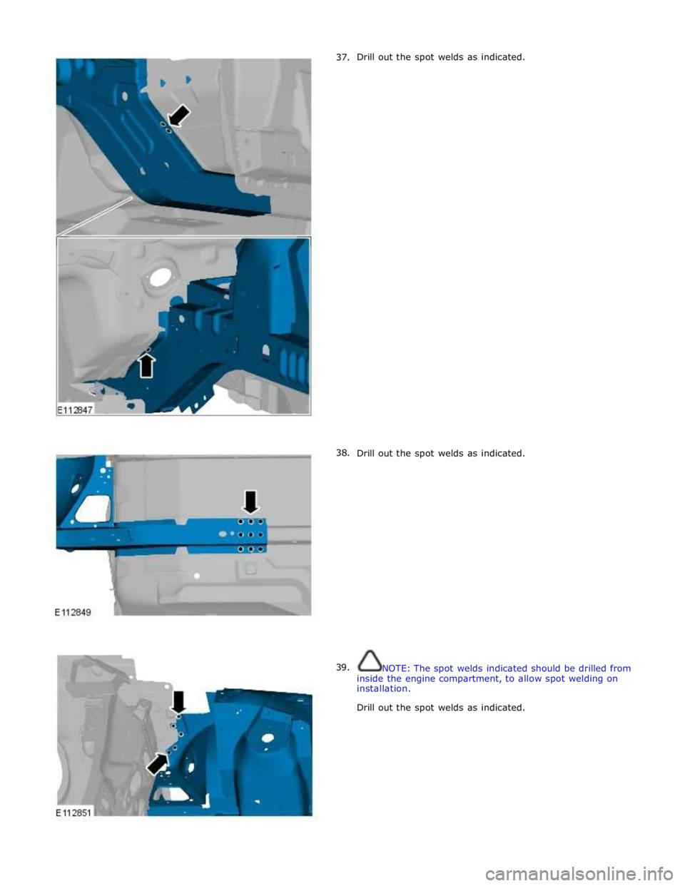
37.
38.
39. Drill out the spot welds as indicated.
Drill out the spot welds as indicated.
NOTE: The spot welds indicated should be drilled from
inside the engine compartment, to allow spot welding on
installation.
Drill out the spot welds as indicated.
Page 2807 of 3039
Published: 11-May-2011
Front End Sheet Metal Repairs - Front Side Member Closing Panel
Removal and Installation
Removal
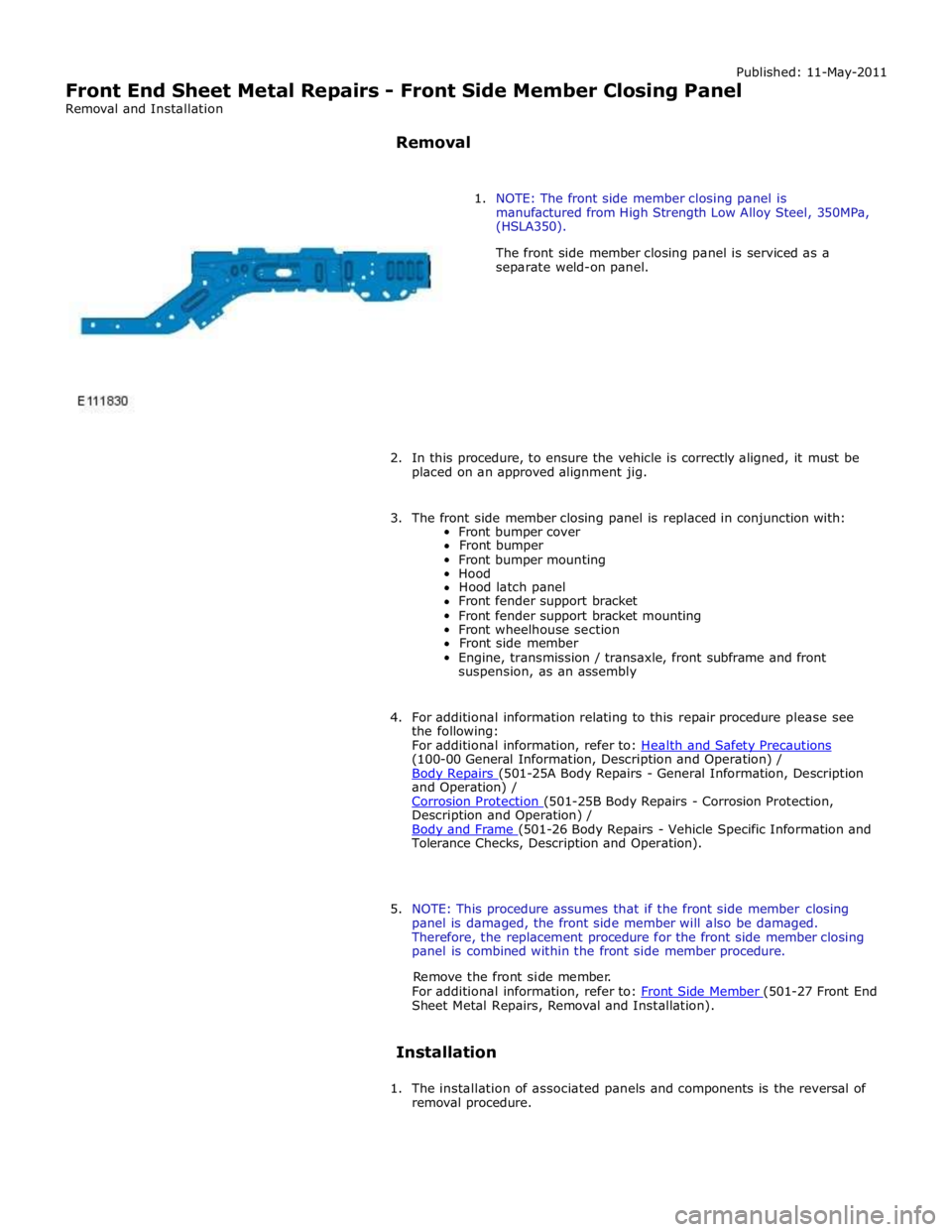
1. NOTE: The front side member closing panel is
manufactured from High Strength Low Alloy Steel, 350MPa,
(HSLA350).
The front side member closing panel is serviced as a
separate weld-on panel.
2. In this procedure, to ensure the vehicle is correctly aligned, it must be
placed on an approved alignment jig.
3. The front side member closing panel is replaced in conjunction with:
Front bumper cover
Front bumper
Front bumper mounting
Hood
Hood latch panel
Front fender support bracket
Front fender support bracket mounting
Front wheelhouse section
Front side member
Engine, transmission / transaxle, front subframe and front
suspension, as an assembly
4. For additional information relating to this repair procedure please see
the following:
For additional information, refer to: Health and Safety Precautions (100-00 General Information, Description and Operation) /
Body Repairs (501-25A Body Repairs - General Information, Description and Operation) /
Corrosion Protection (501-25B Body Repairs - Corrosion Protection, Description and Operation) /
Body and Frame (501-26 Body Repairs - Vehicle Specific Information and Tolerance Checks, Description and Operation).
5. NOTE: This procedure assumes that if the front side member closing
panel is damaged, the front side member will also be damaged.
Therefore, the replacement procedure for the front side member closing
panel is combined within the front side member procedure.
Remove the front side member.
For additional information, refer to: Front Side Member (501-27 Front End Sheet Metal Repairs, Removal and Installation).
Installation
1. The installation of associated panels and components is the reversal of
removal procedure.