2010 JAGUAR XFR Electrical
[x] Cancel search: ElectricalPage 1283 of 3039

Published: 11-May-2011
Engine Emission Control - V8 5.0L Petrol/V8 S/C 5.0L Petrol - Engine Emission
Control
Diagnosis and Testing
Principles of Operation
For a detailed description of the engine emission control system and operation, refer to the relevant Description and Operation
section of the workshop manual. REFER to: (303-08C Engine Emission Control - V8 5.0L Petrol/V8 S/C 5.0L Petrol)
Engine Emission Control (Description and Operation), Engine Emission Control (Description and Operation), Engine Emission Control (Description and Operation).
Inspection and Verification
CAUTION: Diagnosis by substitution from a donor vehicle is NOT acceptable. Substitution of control modules does not
guarantee confirmation of a fault and may also cause additional faults in the vehicle being checked and/or the donor vehicle.
NOTE: Check and rectify basic faults before beginning diagnostic routines involving pinpoint tests.
1. Verify the customer concern.
2. Visually inspect for obvious signs of mechanical or electrical damage.
Visual Inspection
Mechanical Electrical
Exhaust gas recirculation system
Breather hoses
Positive crankcase ventilation valve
Fuel level
Fuel contamination/grade/quality
Throttle body
Fuses
Loose or corroded electrical connectors
Exhaust Gas Recirculation (EGR) valve
Engine Control Module (ECM)
3. If an obvious cause for an observed or reported concern is found, correct the cause (if possible) before proceeding to
the next step.
4. If the cause is not visually evident, verify the symptom and refer to the Symptom Chart, alternatively check for
Diagnostic Trouble Codes (DTCs) and refer to the DTC Index.
Symptom Chart
Symptom Possible Causes Action Difficult to
start cold
Battery
Crankshaft Position (CKP)
sensor
Exhaust Gas Recirculation
(EGR) valve stuck open
Fuel system
Evaporative emissions purge
valve For battery information, CKP sensor, fuel system and purge valve tests,
refer to relevant workshop manual section. Check the EGR valve. Engine stalls
soon after
start
Breather system
disconnected/restricted
Engine Control Module (ECM)
relay
MAF sensor
Ignition system
Air filter restricted
Air leakage
Fuel lines Check the engine breather hoses, PCV, etc. Check the Engine Control
Module (ECM) relay operation. For MAF sensor, ignition system tests, air
intake and fuel line information, refer to relevant workshop manual
section. Poor throttle
response
APP sensor malfunction
TP sensors
ECT sensor
MAF sensor
Transmission malfunction
Traction control event Air
leakage For APP, TP, ECT, MAF sensor tests, intake system checks and
transmission information, refer to relevant workshop manual section.
Check the breather system hoses, PCV, etc.
Page 1299 of 3039

Published: 11-May-2011
Intake Air Distribution and Filtering - V8 S/C 5.0L Petrol - Intake Air
Distribution and Filtering
Diagnosis and Testing
Principles of Operation
For a detailed description of the intake air distribution and filtering system and operation, refer to the relevant Description and
Operation section of the workshop manual. REFER to: (303-12D Intake Air Distribution and Filtering - V8 S/C 5.0L Petrol)
Intake Air Distribution and Filtering (Description and Operation), Intake Air Distribution and Filtering (Description and Operation), Intake Air Distribution and Filtering (Description and Operation).
Inspection and Verification
CAUTION: Diagnosis by substitution from a donor vehicle is NOT acceptable. Substitution of control modules does not
guarantee confirmation of a fault and may also cause additional faults in the vehicle being checked and/or the donor vehicle.
NOTE: Check and rectify basic faults before beginning diagnostic routines involving pinpoint tests.
1. Verify the customer concern.
2. Visually inspect for obvious signs of mechanical or electrical damage.
Visual Inspection
Mechanical Electrical
Hoses and ducts (damage/connections)
Air cleaner element (contaminated/blocked)
Restricted air intake
Supercharger
Supercharger (cooling fan) drive belt
Supercharger seals and gaskets
Charge air coolers (damage/connection)
Mass Air Flow (MAF) sensor
Manifold Absolute Pressure (MAP) sensor
Manifold Absolute Pressure/Temperature (MAPT) sensor
Throttle body
Harness (security/damage)
Connections (security/damage)
3. If an obvious cause for an observed or reported concern is found, correct the cause (if possible) before proceeding to
the next step.
4. If the cause is not visually evident, verify the symptom and refer to the Symptom Chart, alternatively check for
Diagnostic Trouble Codes (DTCs) and refer to the DTC Index.
Symptom Chart
Symptom Possible Causes Action Vehicle does not
start/hard
starting/poor
performance
Restricted/Blocked air intake
Restricted/Blocked air
cleaner element Clear the restriction. Replace the air cleaner element as necessary.
Refer to the relevant workshop manual section. Excessive intake
noise
Intake pipe
disconnected/damaged after
the air cleaner
Air cleaner assembly
incorrectly
assembled/damaged Check the intake system and hoses for correct installation/damage.
Refer to the relevant workshop manual section. Lack of boost
Supercharger drive belt
broken/slipping
Supercharger fault
Supercharger air intake fault
Major air leakage (after the
supercharger) Check the supercharger and drive belt. Check the charge air coolers.
Refer to the relevant workshop manual section. Noise
Supercharger drive belt
slipping
Supercharger fault
Major air leakage (after the
supercharger) Check the supercharger and drive belt. Remove the supercharger drive
belt and recheck for noise. Turn the supercharger by hand and check
for excessive resistance. Check for excessive play at the supercharger
pulley. Check the charge air coolers. Refer to the relevant workshop
manual section.
Page 1349 of 3039
Published: 03-Jun-2014
Evaporative Emissions - V8 5.0L Petrol/V8 S/C 5.0L Petrol - Evaporative
Emissions
Diagnosis and Testing
Principles of Operation
For a detailed description of the Evaporative Emissions system, refer to the relevant Description and Operation section in the
workshop manual.
Inspection and Verification
CAUTION: Diagnosis by substitution from a donor vehicle is NOT acceptable. Substitution of control modules does not
guarantee confirmation of a fault, and may also cause additional faults in the vehicle being tested and/or the donor vehicle.
NOTES:
If a control module or a component is suspect and the vehicle remains under manufacturer warranty, refer to the Warranty
Policy and Procedures manual, or determine if any prior approval programme is in operation, prior to the installation of a new
module/component.
When performing voltage or resistance tests, always use a digital multimeter accurate to three decimal places, and with
an up-to-date calibration certificate. When testing resistance always take the resistance of the digital multimeter leads into
account.
Check and rectify basic faults before beginning diagnostic routines involving pinpoint tests.
1. Verify the customer concern
2. Visually inspect for obvious signs of damage and system integrity
Visual Inspection
Mechanical Electrical
Fuel filler cap and seal
Fuel filler neck
Fuel pipes
Fuel tank
Evaporative emissions canister
Purge valve
Fuses
Wiring harnesses and connectors
Engine Control Module (ECM)
Purge valve
3. If an obvious cause for an observed or reported concern is found, correct the cause (if possible) before proceeding to
the next step
4. If the cause is not visually evident, verify the symptom and refer to the Symptom Chart, alternatively check for
Diagnostic Trouble Codes (DTCs) and refer to the DTC Index
5. Check DDW for open campaigns. Refer to the corresponding bulletins and SSMs which may be valid for the specific
customer complaint and carry out the recommendations as required
Symptom Chart
Symptom Possible Causes Action Difficulty in filling
fuel tank
Restriction in the vapour line between the fuel tank and the
carbon canister outlet/atmospheric port
Check for
restrictions/damage Fuel smell
System leak
Purge valve inoperative
Check for leaks
Check the purge valve
operation DTC Index
For a list of Diagnostic Trouble Codes (DTCs) that could be logged on this vehicle, please refer to Section 100-00.
Page 1362 of 3039
speed.
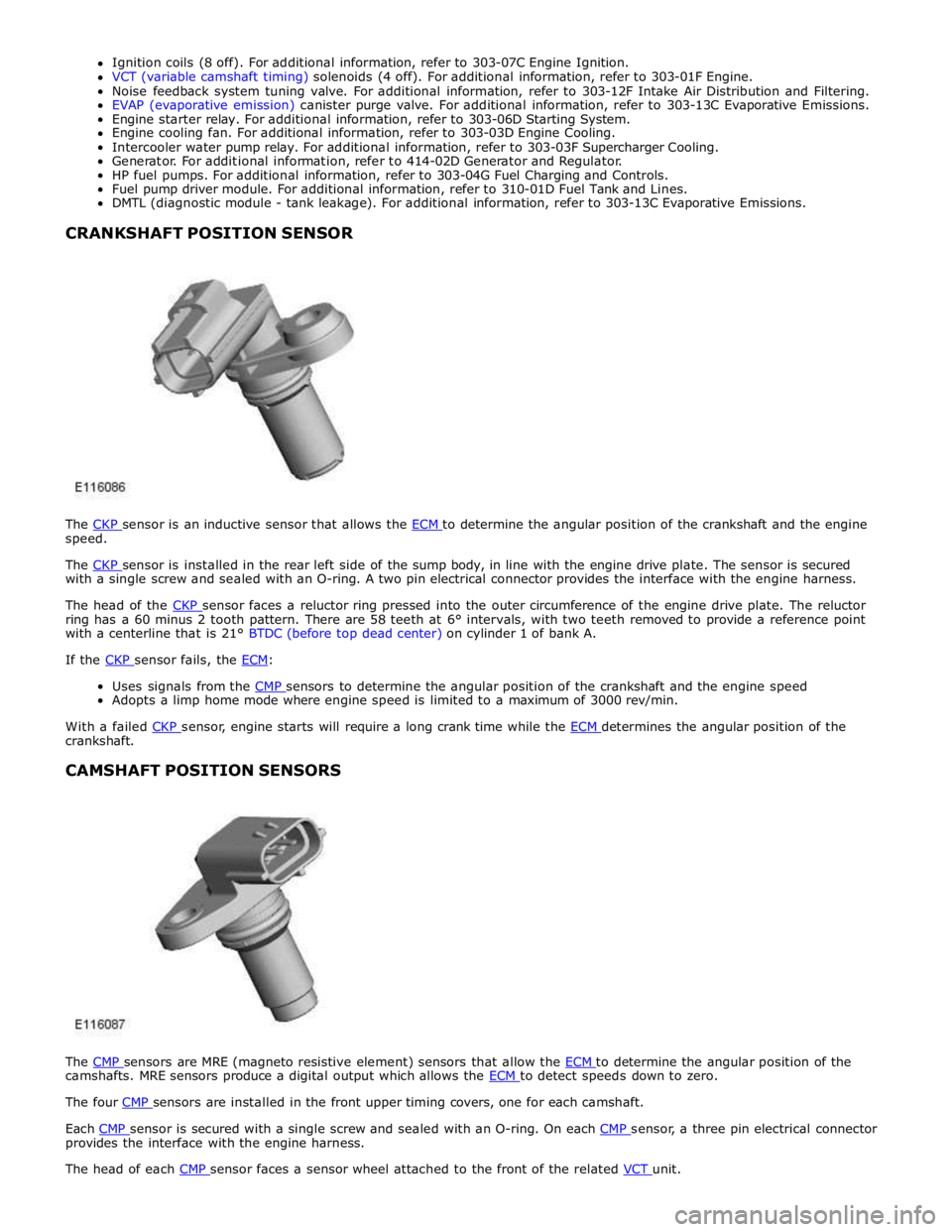
The CKP sensor is installed in the rear left side of the sump body, in line with the engine drive plate. The sensor is secured with a single screw and sealed with an O-ring. A two pin electrical connector provides the interface with the engine harness.
The head of the CKP sensor faces a reluctor ring pressed into the outer circumference of the engine drive plate. The reluctor ring has a 60 minus 2 tooth pattern. There are 58 teeth at 6° intervals, with two teeth removed to provide a reference point
with a centerline that is 21° BTDC (before top dead center) on cylinder 1 of bank A.
If the CKP sensor fails, the ECM:
Uses signals from the CMP sensors to determine the angular position of the crankshaft and the engine speed Adopts a limp home mode where engine speed is limited to a maximum of 3000 rev/min.
With a failed CKP sensor, engine starts will require a long crank time while the ECM determines the angular position of the crankshaft.
CAMSHAFT POSITION SENSORS
The CMP sensors are MRE (magneto resistive element) sensors that allow the ECM to determine the angular position of the camshafts. MRE sensors produce a digital output which allows the ECM to detect speeds down to zero. The four CMP sensors are installed in the front upper timing covers, one for each camshaft.
Each CMP sensor is secured with a single screw and sealed with an O-ring. On each CMP sensor, a three pin electrical connector provides the interface with the engine harness.
The head of each CMP sensor faces a sensor wheel attached to the front of the related VCT unit.
Page 1363 of 3039
Defaults to base mapping for the ignition timing, with no cylinder correction
Disables the VCT system.
ENGINE COOLANT TEMPERATURE SENSORS
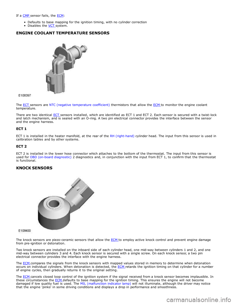
The ECT sensors are NTC (negative temperature coefficient) thermistors that allow the ECM to monitor the engine coolant temperature.
There are two identical ECT sensors installed, which are identified as ECT 1 and ECT 2. Each sensor is secured with a twist-lock and latch mechanism, and is sealed with an O-ring. A two pin electrical connector provides the interface between the sensor
and the engine harness.
ECT 1
ECT 1 is installed in the heater manifold, at the rear of the RH (right-hand) cylinder head. The input from this sensor is used in
calibration tables and by other systems.
ECT 2
ECT 2 is installed in the lower hose connector which attaches to the bottom of the thermostat. The input from this sensor is
used for OBD (on-board diagnostic) 2 diagnostics and, in conjunction with the input from ECT 1, to confirm that the thermostat
is functional.
KNOCK SENSORS
The knock sensors are piezo-ceramic sensors that allow the ECM to employ active knock control and prevent engine damage from pre-ignition or detonation.
Two knock sensors are installed on the inboard side of each cylinder head, one mid-way between cylinders 1 and 2, and one
mid-way between cylinders 3 and 4. Each knock sensor is secured with a single screw. On each knock sensor, a two pin
electrical connector provides the interface with the engine harness.
The ECM compares the signals from the knock sensors with mapped values stored in memory to determine when detonation occurs on individual cylinders. When detonation is detected, the ECM retards the ignition timing on that cylinder for a number of engine cycles, then gradually returns it to the original setting.
The ECM cancels closed loop control of the ignition system if the signal received from a knock sensor becomes implausible. In these circumstances the ECM defaults to base mapping for the ignition timing. This ensures the engine will not become damaged if low quality fuel is used. The MIL (malfunction indicator lamp) will not illuminate, although the driver may notice
that the engine 'pinks' in some driving conditions and displays a drop in performance and smoothness.
Page 1364 of 3039
MANIFOLD ABSOLUTE PRESSURE SENSOR
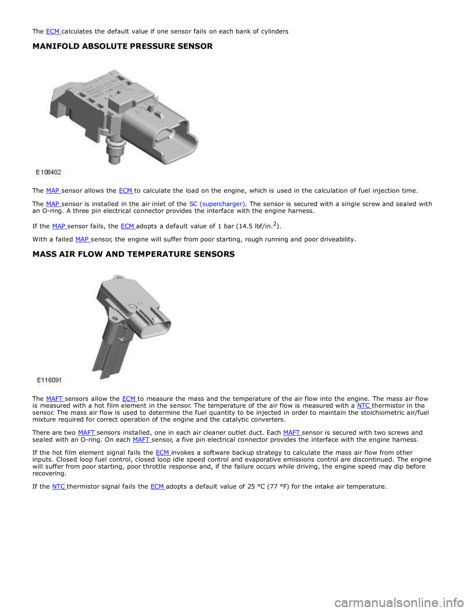
The MAP sensor allows the ECM to calculate the load on the engine, which is used in the calculation of fuel injection time.
The MAP sensor is installed in the air inlet of the SC (supercharger). The sensor is secured with a single screw and sealed with an O-ring. A three pin electrical connector provides the interface with the engine harness.
If the MAP sensor fails, the ECM adopts a default value of 1 bar (14.5 lbf/in.2
). With a failed MAP sensor, the engine will suffer from poor starting, rough running and poor driveability.
MASS AIR FLOW AND TEMPERATURE SENSORS
The MAFT sensors allow the ECM to measure the mass and the temperature of the air flow into the engine. The mass air flow is measured with a hot film element in the sensor. The temperature of the air flow is measured with a NTC thermistor in the sensor. The mass air flow is used to determine the fuel quantity to be injected in order to maintain the stoichiometric air/fuel
mixture required for correct operation of the engine and the catalytic converters.
There are two MAFT sensors installed, one in each air cleaner outlet duct. Each MAFT sensor is secured with two screws and sealed with an O-ring. On each MAFT sensor, a five pin electrical connector provides the interface with the engine harness.
If the hot film element signal fails the ECM invokes a software backup strategy to calculate the mass air flow from other inputs. Closed loop fuel control, closed loop idle speed control and evaporative emissions control are discontinued. The engine
will suffer from poor starting, poor throttle response and, if the failure occurs while driving, the engine speed may dip before
recovering.
If the NTC thermistor signal fails the ECM adopts a default value of 25 °C (77 °F) for the intake air temperature.
Page 1365 of 3039
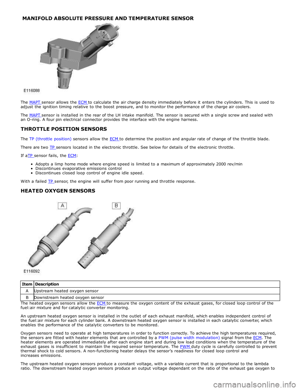
MANIFOLD ABSOLUTE PRESSURE AND TEMPERATURE SENSOR
The MAPT sensor allows the ECM to calculate the air charge density immediately before it enters the cylinders. This is used to adjust the ignition timing relative to the boost pressure, and to monitor the performance of the charge air coolers.
The MAPT sensor is installed in the rear of the LH intake manifold. The sensor is secured with a single screw and sealed with an O-ring. A four pin electrical connector provides the interface with the engine harness.
THROTTLE POSITION SENSORS
The TP (throttle position) sensors allow the ECM to determine the position and angular rate of change of the throttle blade. There are two TP sensors located in the electronic throttle. See below for details of the electronic throttle. If aTP sensor fails, the ECM:
Adopts a limp home mode where engine speed is limited to a maximum of approximately 2000 rev/min
Discontinues evaporative emissions control
Discontinues closed loop control of engine idle speed.
With a failed TP sensor, the engine will suffer from poor running and throttle response.
HEATED OXYGEN SENSORS
Item Description A Upstream heated oxygen sensor B Downstream heated oxygen sensor The heated oxygen sensors allow the ECM to measure the oxygen content of the exhaust gases, for closed loop control of the fuel:air mixture and for catalytic converter monitoring.
An upstream heated oxygen sensor is installed in the outlet of each exhaust manifold, which enables independent control of
the fuel:air mixture for each cylinder bank. A downstream heated oxygen sensor is installed in each catalytic converter, which
enables the performance of the catalytic converters to be monitored.
Oxygen sensors need to operate at high temperatures in order to function correctly. To achieve the high temperatures required,
the sensors are fitted with heater elements that are controlled by a PWM (pulse width modulation) signal from the ECM. The heater elements are operated immediately after each engine start and during low load conditions when the temperature of the
exhaust gases is insufficient to maintain the required sensor temperature. The PWM duty cycle is carefully controlled to prevent thermal shock to cold sensors. A non-functioning heater delays the sensor’s readiness for closed loop control and
increases emissions.
The upstream heated oxygen sensors produce a constant voltage, with a variable current that is proportional to the lambda
ratio. The downstream heated oxygen sensors produce an output voltage dependant on the ratio of the exhaust gas oxygen to
Page 1366 of 3039
the period of rich to lean and lean to rich switching monitors the response rate of the upstream sensors.
Diagnosis of electrical faults is continually monitored in both the upstream and downstream sensors. This is achieved by
checking the signal against maximum and minimum threshold, for open and short circuit conditions.
If a heated oxygen sensor fails:
The ECM defaults to open loop fueling for the related cylinder bank The CO (carbon monoxide) and emissions content of the exhaust gases increases
The exhaust smells of rotten eggs (hydrogen sulphide).
With a failed heated oxygen sensor, the engine will suffer from unstable operation and reduced performance.
ACCELERATOR PEDAL POSITION SENSOR
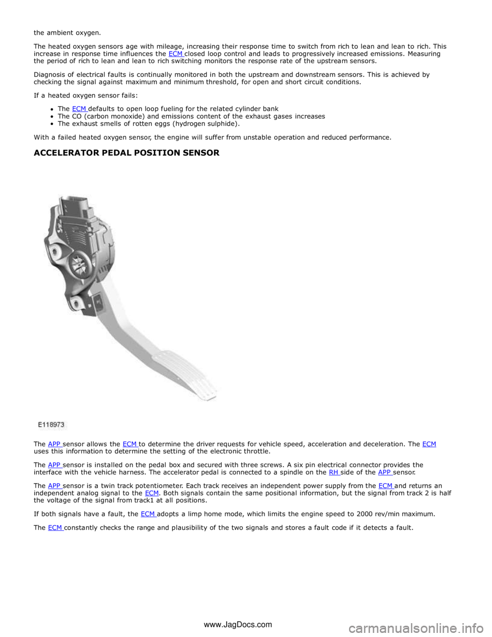
The APP sensor allows the ECM to determine the driver requests for vehicle speed, acceleration and deceleration. The ECM uses this information to determine the setting of the electronic throttle.
The APP sensor is installed on the pedal box and secured with three screws. A six pin electrical connector provides the interface with the vehicle harness. The accelerator pedal is connected to a spindle on the RH side of the APP sensor.
The APP sensor is a twin track potentiometer. Each track receives an independent power supply from the ECM and returns an independent analog signal to the ECM. Both signals contain the same positional information, but the signal from track 2 is half the voltage of the signal from track1 at all positions.
If both signals have a fault, the ECM adopts a limp home mode, which limits the engine speed to 2000 rev/min maximum. The ECM constantly checks the range and plausibility of the two signals and stores a fault code if it detects a fault. www.JagDocs.com