2010 JAGUAR XFR Electrical
[x] Cancel search: ElectricalPage 1189 of 3039
Published: 11-May-2011
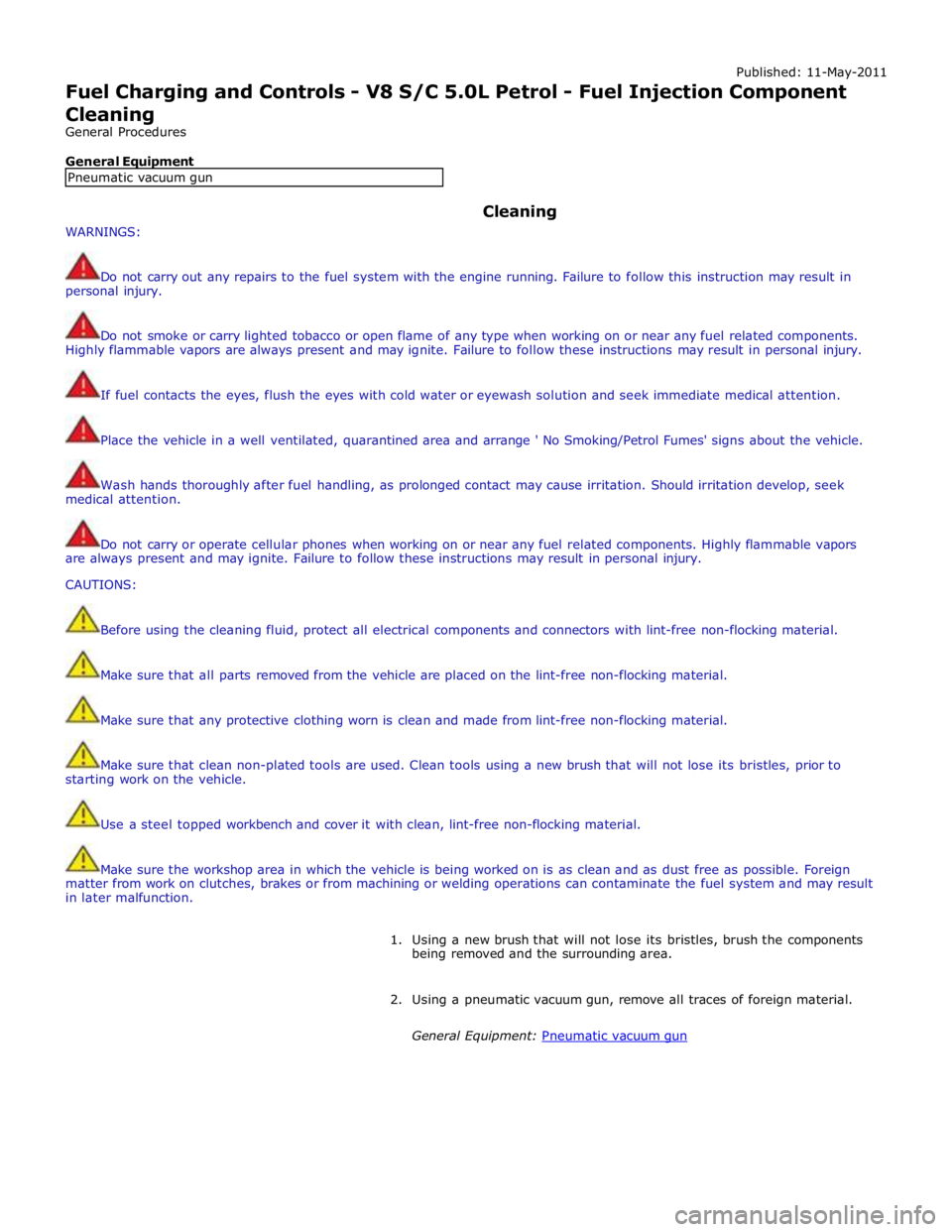
Fuel Charging and Controls - V8 S/C 5.0L Petrol - Fuel Injection Component Cleaning
General Procedures
General Equipment
WARNINGS: Cleaning
Do not carry out any repairs to the fuel system with the engine running. Failure to follow this instruction may result in
personal injury.
Do not smoke or carry lighted tobacco or open flame of any type when working on or near any fuel related components.
Highly flammable vapors are always present and may ignite. Failure to follow these instructions may result in personal injury.
If fuel contacts the eyes, flush the eyes with cold water or eyewash solution and seek immediate medical attention.
Place the vehicle in a well ventilated, quarantined area and arrange ' No Smoking/Petrol Fumes' signs about the vehicle.
Wash hands thoroughly after fuel handling, as prolonged contact may cause irritation. Should irritation develop, seek
medical attention.
Do not carry or operate cellular phones when working on or near any fuel related components. Highly flammable vapors
are always present and may ignite. Failure to follow these instructions may result in personal injury.
CAUTIONS:
Before using the cleaning fluid, protect all electrical components and connectors with lint-free non-flocking material.
Make sure that all parts removed from the vehicle are placed on the lint-free non-flocking material.
Make sure that any protective clothing worn is clean and made from lint-free non-flocking material.
Make sure that clean non-plated tools are used. Clean tools using a new brush that will not lose its bristles, prior to
starting work on the vehicle.
Use a steel topped workbench and cover it with clean, lint-free non-flocking material.
Make sure the workshop area in which the vehicle is being worked on is as clean and as dust free as possible. Foreign
matter from work on clutches, brakes or from machining or welding operations can contaminate the fuel system and may result
in later malfunction.
1. Using a new brush that will not lose its bristles, brush the components
being removed and the surrounding area.
2. Using a pneumatic vacuum gun, remove all traces of foreign material.
General Equipment: Pneumatic vacuum gun Pneumatic vacuum gun
Page 1263 of 3039
Published: 11-May-2011
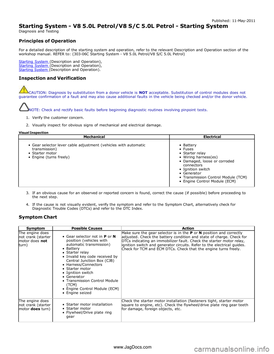
Starting System - V8 5.0L Petrol/V8 S/C 5.0L Petrol - Starting System
Diagnosis and Testing
Principles of Operation
For a detailed description of the starting system and operation, refer to the relevant Description and Operation section of the
workshop manual. REFER to: (303-06C Starting System - V8 5.0L Petrol/V8 S/C 5.0L Petrol)
Starting System (Description and Operation), Starting System (Description and Operation), Starting System (Description and Operation).
Inspection and Verification
CAUTION: Diagnosis by substitution from a donor vehicle is NOT acceptable. Substitution of control modules does not
guarantee confirmation of a fault and may also cause additional faults in the vehicle being checked and/or the donor vehicle.
NOTE: Check and rectify basic faults before beginning diagnostic routines involving pinpoint tests.
1. Verify the customer concern.
2. Visually inspect for obvious signs of mechanical and electrical damage.
Visual Inspection
Mechanical Electrical
Gear selector lever cable adjustment (vehicles with automatic
transmission)
Starter motor
Engine (turns freely)
Battery
Fuses
Starter relay
Wiring harness(es)
Damaged, loose or corroded
connectors
Ignition switch
Generator
Transmission Control Module (TCM)
Engine Control Module (ECM)
3. If an obvious cause for an observed or reported concern is found, correct the cause (if possible) before proceeding to
the next step.
4. If the cause is not visually evident, verify the symptom and refer to the Symptom Chart, alternatively check for
Diagnostic Trouble Codes (DTCs) and refer to the DTC Index.
Symptom Chart
Symptom Possible Causes Action The engine does
not crank (starter
motor does not
turn)
Gear selector not in P or N
position (vehicles with
automatic transmission)
Battery
Starter relay
Invalid key code received by
Central Junction Box (CJB)
Harness/Connectors
Starter motor
Ignition switch
Generator
Transmission Control Module
(TCM)
Engine Control Module (ECM)
Engine seized Make sure the gear selector is in the P or N position and correctly
adjusted. Check the battery condition and state of charge. Check for
DTCs indicating an immobilizer fault. Check the starter motor relay,
ignition switch and generator circuits. Refer to the electrical guides.
Check for TCM and ECM DTCs. Check that the engine turns freely. The engine does
not crank (starter
motor does turn)
Starter motor installation
Starter motor
Flywheel/Drive plate ring
gear Check the starter motor installation (fasteners tight, starter motor
square to engine, etc). Check the flywheel/drive plate ring gear teeth
for damage, foreign objects, etc. www.JagDocs.com
Page 1264 of 3039
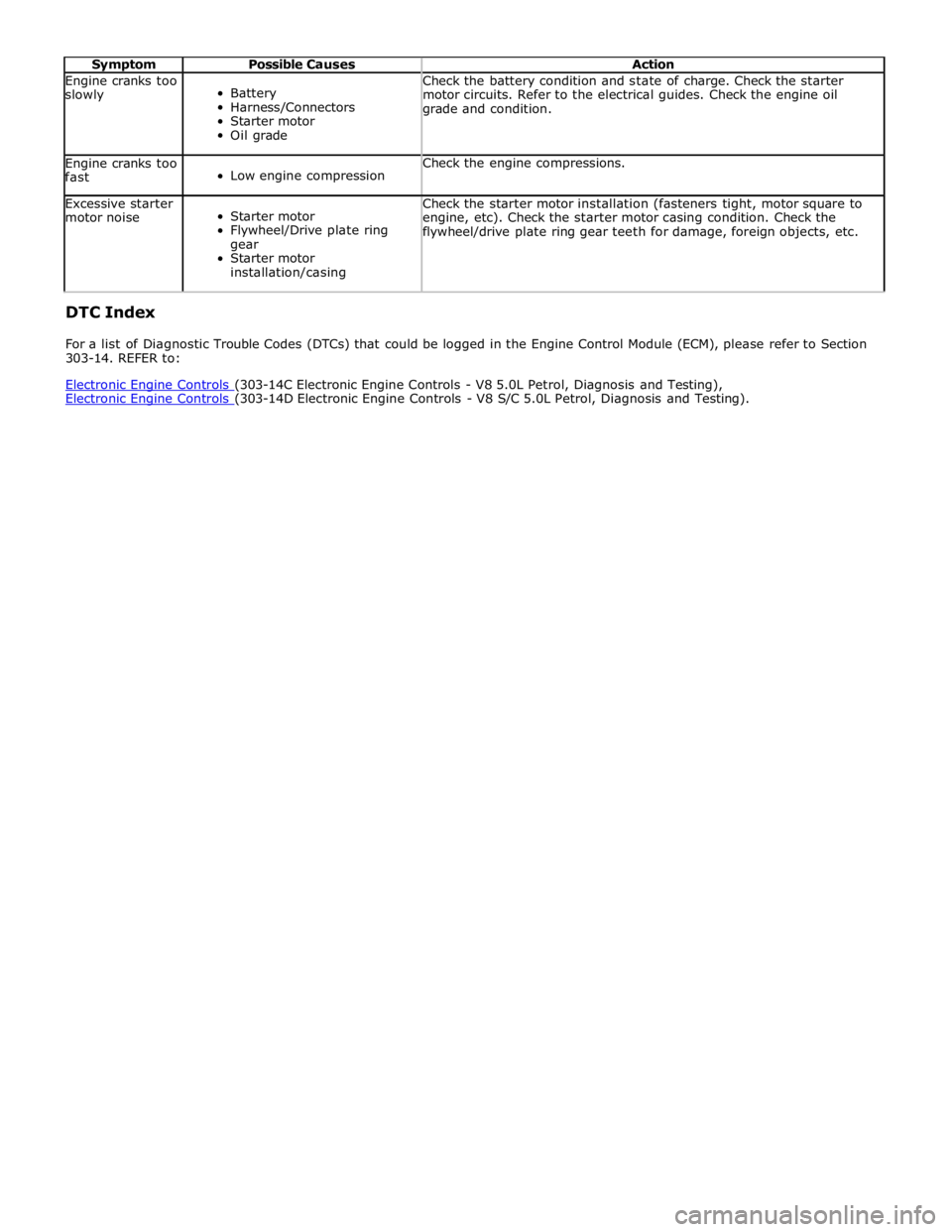
Symptom Possible Causes Action Engine cranks too
slowly
Battery
Harness/Connectors
Starter motor
Oil grade Check the battery condition and state of charge. Check the starter
motor circuits. Refer to the electrical guides. Check the engine oil
grade and condition. Engine cranks too
fast
Low engine compression Check the engine compressions. Excessive starter
motor noise
Starter motor
Flywheel/Drive plate ring
gear
Starter motor
installation/casing Check the starter motor installation (fasteners tight, motor square to
engine, etc). Check the starter motor casing condition. Check the
flywheel/drive plate ring gear teeth for damage, foreign objects, etc. DTC Index
For a list of Diagnostic Trouble Codes (DTCs) that could be logged in the Engine Control Module (ECM), please refer to Section
303-14. REFER to:
Electronic Engine Controls (303-14C Electronic Engine Controls - V8 5.0L Petrol, Diagnosis and Testing), Electronic Engine Controls (303-14D Electronic Engine Controls - V8 S/C 5.0L Petrol, Diagnosis and Testing).
Page 1265 of 3039
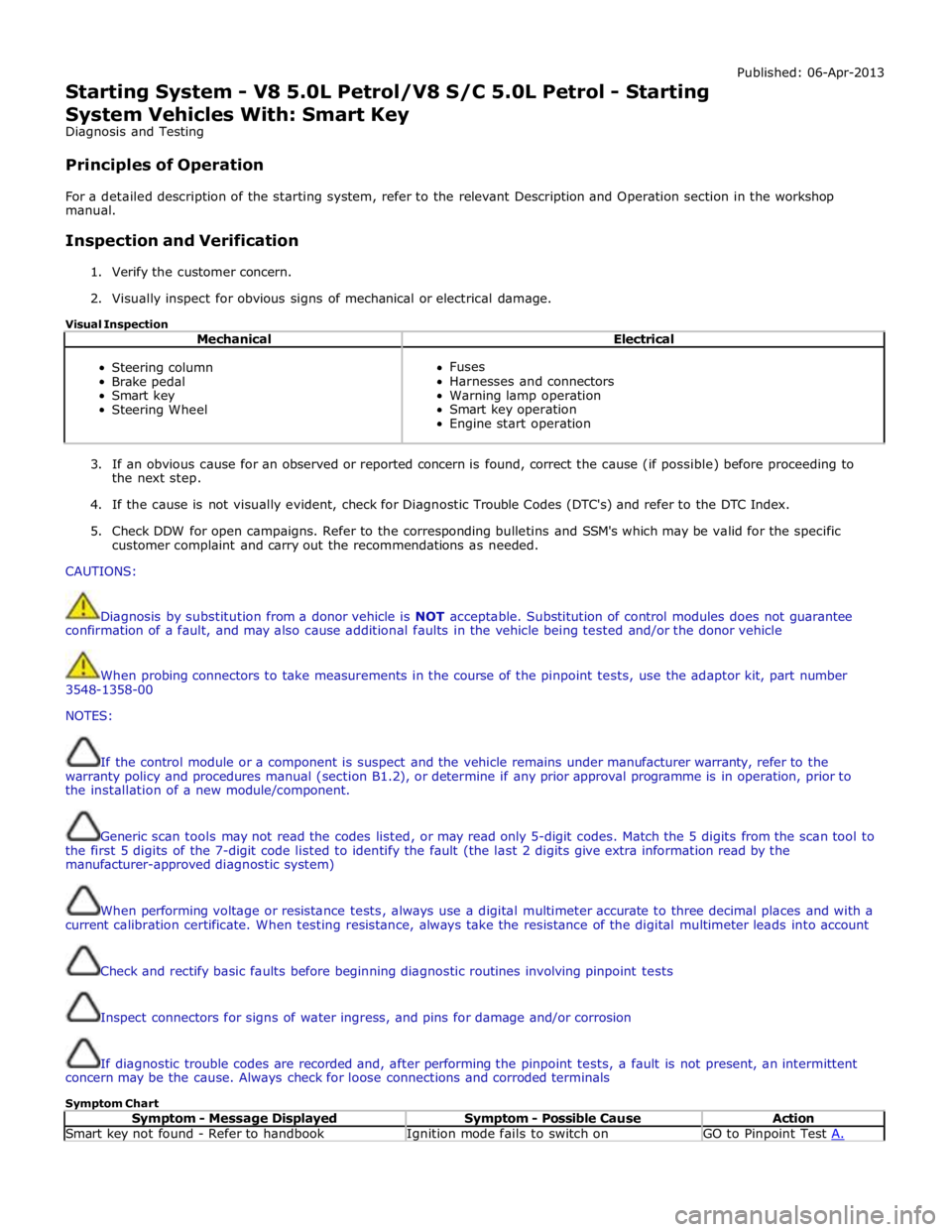
Starting System - V8 5.0L Petrol/V8 S/C 5.0L Petrol - Starting
System Vehicles With: Smart Key
Diagnosis and Testing
Principles of Operation Published: 06-Apr-2013
For a detailed description of the starting system, refer to the relevant Description and Operation section in the workshop
manual.
Inspection and Verification
1. Verify the customer concern.
2. Visually inspect for obvious signs of mechanical or electrical damage.
Visual Inspection
Mechanical Electrical
Steering column
Brake pedal
Smart key
Steering Wheel
Fuses
Harnesses and connectors
Warning lamp operation
Smart key operation
Engine start operation
3. If an obvious cause for an observed or reported concern is found, correct the cause (if possible) before proceeding to
the next step.
4. If the cause is not visually evident, check for Diagnostic Trouble Codes (DTC's) and refer to the DTC Index.
5. Check DDW for open campaigns. Refer to the corresponding bulletins and SSM's which may be valid for the specific
customer complaint and carry out the recommendations as needed.
CAUTIONS:
Diagnosis by substitution from a donor vehicle is NOT acceptable. Substitution of control modules does not guarantee
confirmation of a fault, and may also cause additional faults in the vehicle being tested and/or the donor vehicle
When probing connectors to take measurements in the course of the pinpoint tests, use the adaptor kit, part number
3548-1358-00
NOTES:
If the control module or a component is suspect and the vehicle remains under manufacturer warranty, refer to the
warranty policy and procedures manual (section B1.2), or determine if any prior approval programme is in operation, prior to
the installation of a new module/component.
Generic scan tools may not read the codes listed, or may read only 5-digit codes. Match the 5 digits from the scan tool to
the first 5 digits of the 7-digit code listed to identify the fault (the last 2 digits give extra information read by the
manufacturer-approved diagnostic system)
When performing voltage or resistance tests, always use a digital multimeter accurate to three decimal places and with a
current calibration certificate. When testing resistance, always take the resistance of the digital multimeter leads into account
Check and rectify basic faults before beginning diagnostic routines involving pinpoint tests
Inspect connectors for signs of water ingress, and pins for damage and/or corrosion
If diagnostic trouble codes are recorded and, after performing the pinpoint tests, a fault is not present, an intermittent
concern may be the cause. Always check for loose connections and corroded terminals
Symptom Chart
Symptom - Message Displayed Symptom - Possible Cause Action Smart key not found - Refer to handbook Ignition mode fails to switch on GO to Pinpoint Test A.
Page 1266 of 3039
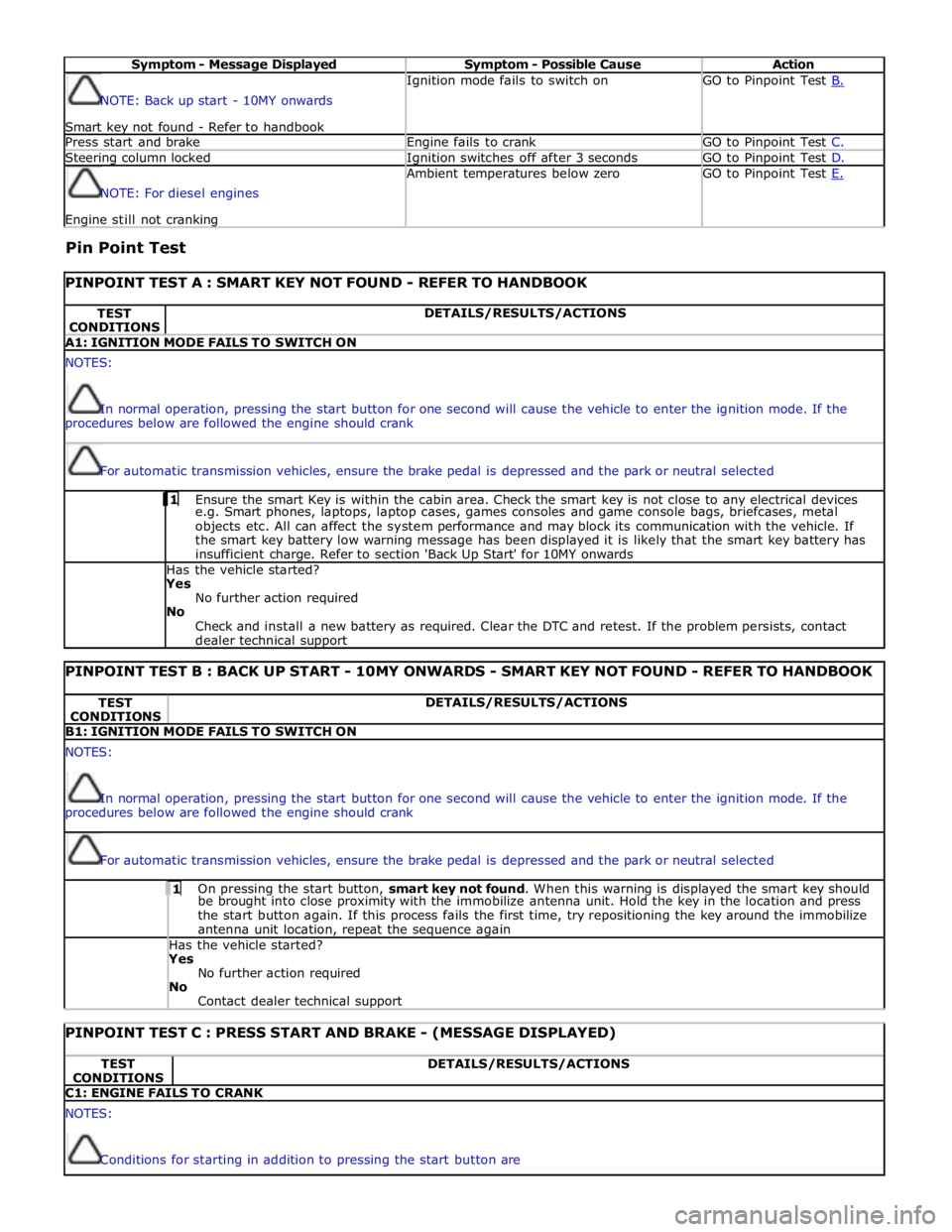
Symptom - Message Displayed Symptom - Possible Cause Action NOTE: Back up start - 10MY onwards
Smart key not found - Refer to handbook Ignition mode fails to switch on GO to Pinpoint Test B. Press start and brake Engine fails to crank GO to Pinpoint Test C. Steering column locked Ignition switches off after 3 seconds GO to Pinpoint Test D. NOTE: For diesel engines Engine still not cranking Ambient temperatures below zero GO to Pinpoint Test E.
Pin Point Test
PINPOINT TEST A : SMART KEY NOT FOUND - REFER TO HANDBOOK TEST
CONDITIONS DETAILS/RESULTS/ACTIONS A1: IGNITION MODE FAILS TO SWITCH ON NOTES:
In normal operation, pressing the start button for one second will cause the vehicle to enter the ignition mode. If the
procedures below are followed the engine should crank
For automatic transmission vehicles, ensure the brake pedal is depressed and the park or neutral selected 1 Ensure the smart Key is within the cabin area. Check the smart key is not close to any electrical devices e.g. Smart phones, laptops, laptop cases, games consoles and game console bags, briefcases, metal
objects etc. All can affect the system performance and may block its communication with the vehicle. If
the smart key battery low warning message has been displayed it is likely that the smart key battery has
insufficient charge. Refer to section 'Back Up Start' for 10MY onwards Has the vehicle started? Yes
No further action required
No
Check and install a new battery as required. Clear the DTC and retest. If the problem persists, contact
dealer technical support
PINPOINT TEST B : BACK UP START - 10MY ONWARDS - SMART KEY NOT FOUND - REFER TO HANDBOOK TEST
CONDITIONS DETAILS/RESULTS/ACTIONS B1: IGNITION MODE FAILS TO SWITCH ON NOTES:
In normal operation, pressing the start button for one second will cause the vehicle to enter the ignition mode. If the
procedures below are followed the engine should crank
For automatic transmission vehicles, ensure the brake pedal is depressed and the park or neutral selected 1 On pressing the start button, smart key not found. When this warning is displayed the smart key should be brought into close proximity with the immobilize antenna unit. Hold the key in the location and press
the start button again. If this process fails the first time, try repositioning the key around the immobilize
antenna unit location, repeat the sequence again Has the vehicle started? Yes
No further action required
No
Contact dealer technical support
PINPOINT TEST C : PRESS START AND BRAKE - (MESSAGE DISPLAYED) TEST
CONDITIONS DETAILS/RESULTS/ACTIONS C1: ENGINE FAILS TO CRANK NOTES:
Conditions for starting in addition to pressing the start button are
Page 1268 of 3039
Published: 11-May-2011
Starting System - V8 5.0L Petrol/V8 S/C 5.0L Petrol - Starter Motor
Removal and Installation
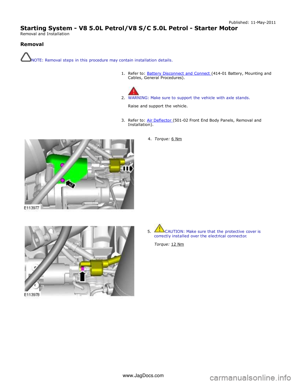
Removal
NOTE: Removal steps in this procedure may contain installation details.
1. Refer to: Battery Disconnect and Connect (414-01 Battery, Mounting and Cables, General Procedures).
2. WARNING: Make sure to support the vehicle with axle stands.
Raise and support the vehicle.
3. Refer to: Air Deflector (501-02 Front End Body Panels, Removal and Installation).
4. Torque: 6 Nm 5. CAUTION: Make sure that the protective cover is
correctly installed over the electrical connector.
Torque: 12 Nm www.JagDocs.com
Page 1274 of 3039
GENERAL System Operation
The ignition coils are supplied with electrical power from the battery via a 250 A megafuse in the BJB (battery junction box)
and the ignition relay in the EJB (engine junction box). The control signal for the ignition relay is supplied by the CJB (central
junction box).
The ECM (engine control module) sends a separate signal to each ignition coil to trigger the power stage switching. The ECM calculates the dwell time from the battery voltage and engine speed, to ensure a constant energy level is produced in the
secondary coil each time the power stage is switched. This ensures sufficient spark energy is available without excessive
primary current flow, which avoids overheating and damage to the ignition coils.
The ECM calculates the ignition timing for individual cylinders from: Engine speed
Camshaft position
Engine load
Engine temperature
The knock control function
The shift control function
The idle speed control function.
IGNITION COILS Component Description
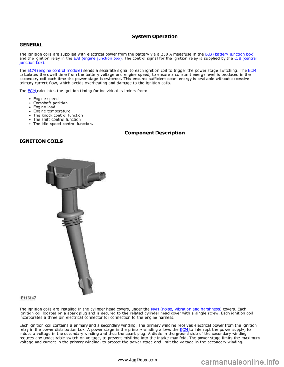
The ignition coils are installed in the cylinder head covers, under the NVH (noise, vibration and harshness) covers. Each
ignition coil locates on a spark plug and is secured to the related cylinder head cover with a single screw. Each ignition coil
incorporates a three pin electrical connector for connection to the engine harness.
Each ignition coil contains a primary and a secondary winding. The primary winding receives electrical power from the ignition
relay in the power distribution box. A power stage in the primary winding allows the ECM to interrupt the power supply, to induce a voltage in the secondary winding and thus the spark plug. A diode in the ground side of the secondary winding
reduces any undesirable switch-on voltage, to prevent misfiring into the intake manifold. The power stage limits the maximum
voltage and current in the primary winding, to protect the power stage and limit the voltage in the secondary winding. www.JagDocs.com
Page 1276 of 3039
Published: 11-May-2011
Engine Ignition - V8 5.0L Petrol/V8 S/C 5.0L Petrol - Engine Ignition
Diagnosis and Testing
Principles of Operation
For a detailed description of the engine ignition system and operation, refer to the relevant Description and Operation section
of the workshop manual. REFER to: (303-07B Engine Ignition - V8 5.0L Petrol/V8 S/C 5.0L Petrol)
Engine Ignition (Description and Operation), Engine Ignition (Description and Operation), Engine Ignition (Description and Operation).
Inspection and Verification
CAUTION: Diagnosis by substitution from a donor vehicle is NOT acceptable. Substitution of control modules does not
guarantee confirmation of a fault and may also cause additional faults in the vehicle being checked and/or the donor vehicle.
NOTE: Check and rectify basic faults before beginning diagnostic routines involving pinpoint tests.
1. Verify the customer concern.
2. Visually inspect for obvious signs of mechanical and electrical damage.
Visual Inspection
Mechanical Electrical
Engine oil level
Cooling system coolant level
Fuel level
Fuel contamination/grade/quality
Exhaust gas recirculation (EGR) valves
Fuses
Wiring harness
Loose or corroded electrical connectors
Ignition coils
Sensor(s)
Engine Control Module (ECM)
Transmission Control Module (TCM)
3. If an obvious cause for an observed or reported concern is found, correct the cause (if possible) before proceeding to
the next step.
4. If the cause is not visually evident, verify the symptom and refer to the Symptom Chart, alternatively check for
Diagnostic Trouble Codes (DTCs) and refer to the DTC Index.
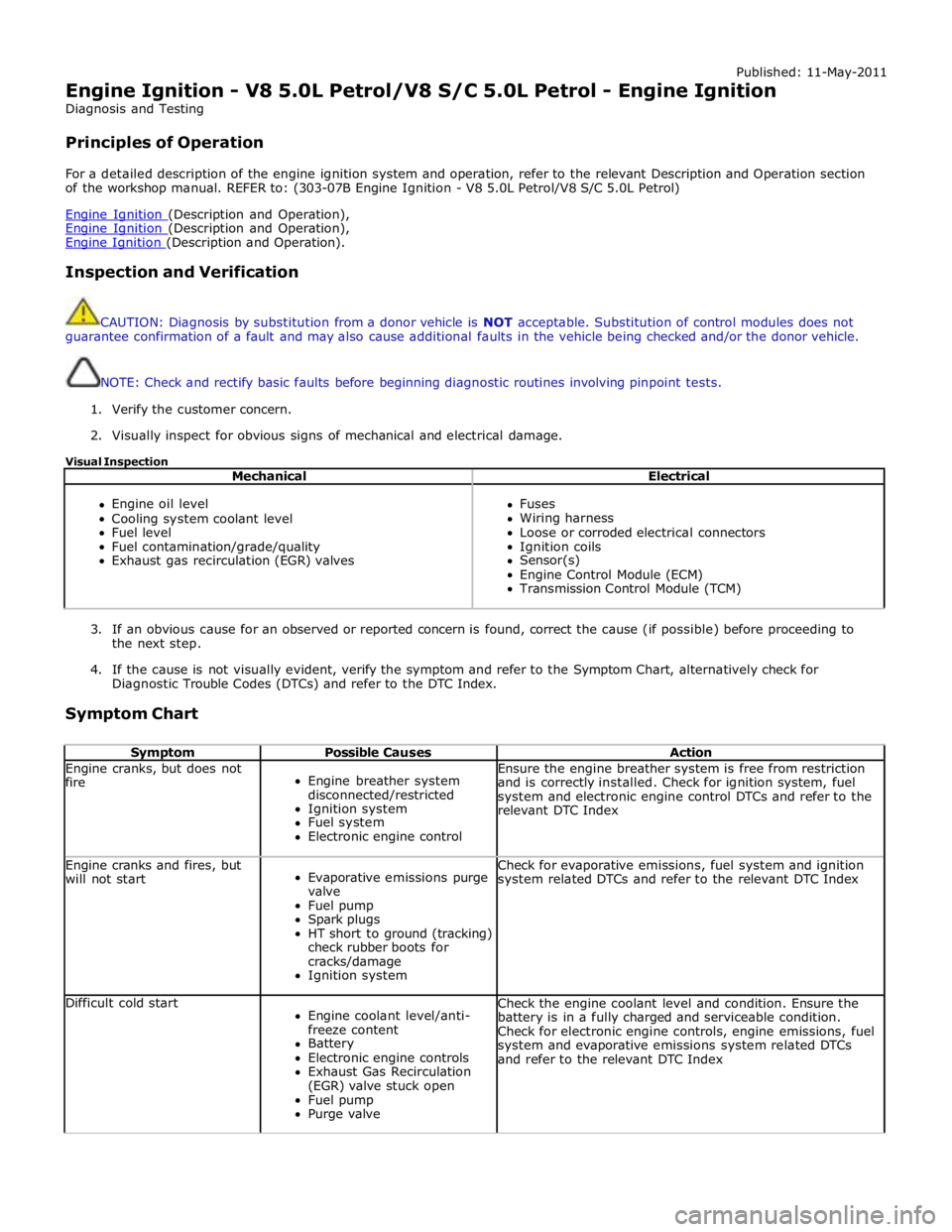
Symptom Chart
Symptom Possible Causes Action Engine cranks, but does not
fire
Engine breather system
disconnected/restricted
Ignition system
Fuel system
Electronic engine control Ensure the engine breather system is free from restriction
and is correctly installed. Check for ignition system, fuel
system and electronic engine control DTCs and refer to the
relevant DTC Index Engine cranks and fires, but
will not start
Evaporative emissions purge
valve
Fuel pump
Spark plugs
HT short to ground (tracking)
check rubber boots for
cracks/damage
Ignition system Check for evaporative emissions, fuel system and ignition
system related DTCs and refer to the relevant DTC Index Difficult cold start
Engine coolant level/anti-
freeze content
Battery
Electronic engine controls
Exhaust Gas Recirculation
(EGR) valve stuck open
Fuel pump
Purge valve Check the engine coolant level and condition. Ensure the
battery is in a fully charged and serviceable condition.
Check for electronic engine controls, engine emissions, fuel
system and evaporative emissions system related DTCs
and refer to the relevant DTC Index