2010 JAGUAR XFR Electrical
[x] Cancel search: ElectricalPage 861 of 3039
16 Bias spring 17 Snap ring 18 Reluctor ring 19 Center plate 20 Snap ring 21 Screw (6 off) 22 Spool valve 23 Outer plate Each VCT unit is attached to the camshaft by three bolts. A rotor assembly and a reed plate are installed inside a sprocket housing, which consists of a sprocket, an outer plate and an inner plate held together by six screws.
A reluctor ring, for the CMP (camshaft position) sensor, a center plate and a bias spring are installed at the front of the VCT unit. The ends of the bias spring locate on the center plate assembly and the sprocket housing, to give a turning moment to
the camshaft in the advance direction. A snap ring locates the reluctor ring on to a sleeve installed in the center of the rotor
assembly. The opposite end of the sleeve locates in a bore in the front face of the camshaft, which contains a filter.
A spring and spool valve are installed in the rotor assembly sleeve and retained by a snap ring. The spring keeps the spool
valve in contact with the armature of the related VCT solenoid.
Each VCT unit is supplied with engine oil from an oil gallery in the cylinder head, through the camshaft front bearing cap and a bore in the center of the camshaft.
Variable Camshaft Timing Solenoids
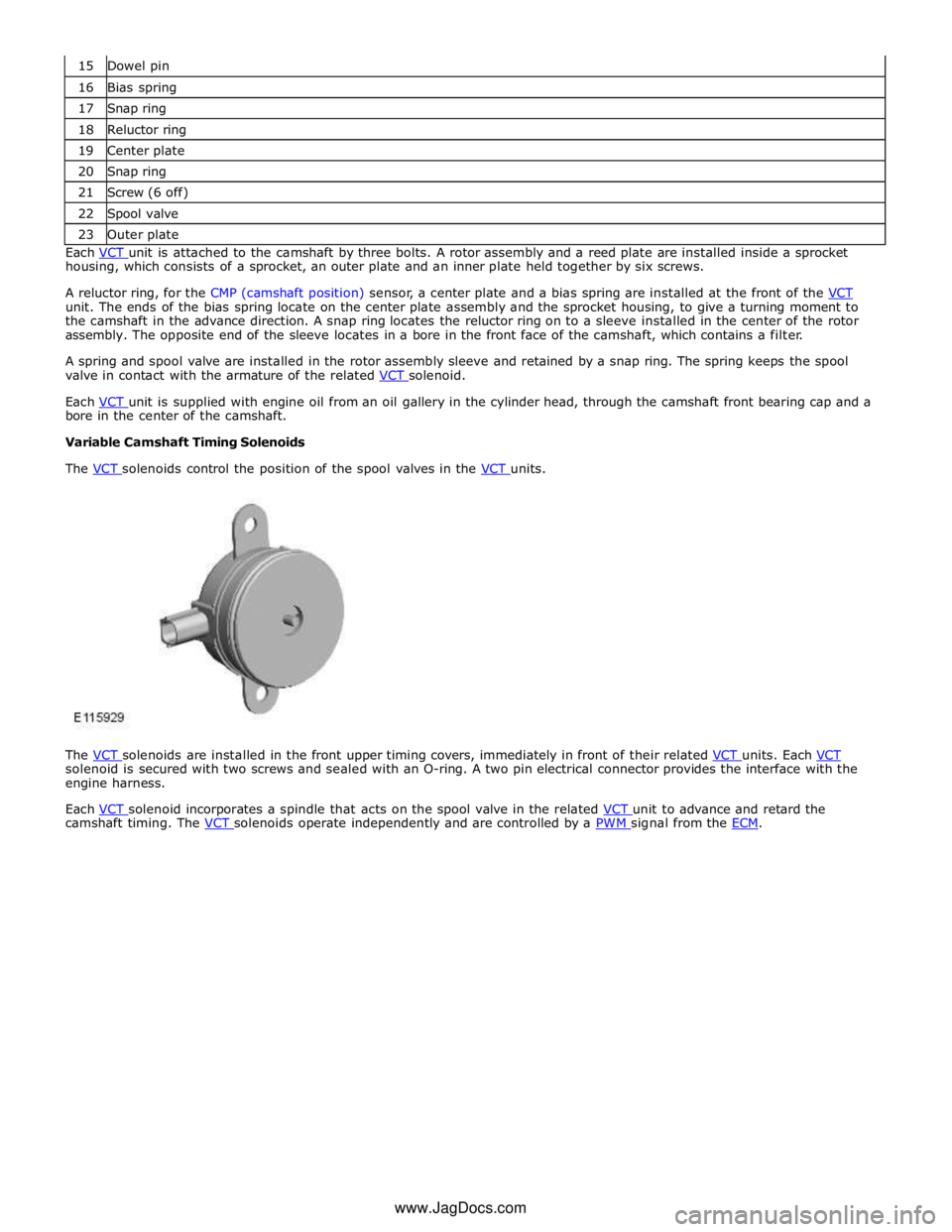
The VCT solenoids control the position of the spool valves in the VCT units.
The VCT solenoids are installed in the front upper timing covers, immediately in front of their related VCT units. Each VCT solenoid is secured with two screws and sealed with an O-ring. A two pin electrical connector provides the interface with the
engine harness.
Each VCT solenoid incorporates a spindle that acts on the spool valve in the related VCT unit to advance and retard the camshaft timing. The VCT solenoids operate independently and are controlled by a PWM signal from the ECM. www.JagDocs.com
Page 1118 of 3039
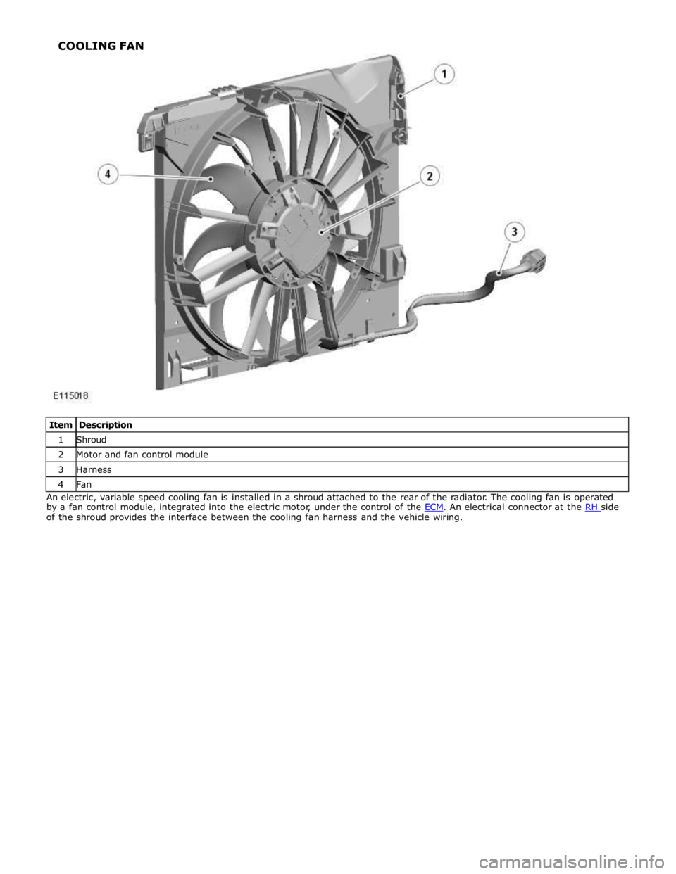
1 Shroud 2 Motor and fan control module 3 Harness 4 Fan An electric, variable speed cooling fan is installed in a shroud attached to the rear of the radiator. The cooling fan is operated
by a fan control module, integrated into the electric motor, under the control of the ECM. An electrical connector at the RH side of the shroud provides the interface between the cooling fan harness and the vehicle wiring. COOLING FAN
Page 1122 of 3039
Published: 17-Apr-2014
Engine Cooling - V8 5.0L Petrol/V8 S/C 5.0L Petrol - Engine Cooling V8 5.0L
Petrol/V8 S/C 5.0L Petrol
Diagnosis and Testing
Principle of Operation
For a detailed description of the engine cooling system and operation, refer to the relevant description and operation section of
the workshop manual. Engine Cooling, Section - 303-03
Inspection and Verification
WARNING: Moving parts can cause severe injury, keep clear of moving parts, never place your hands or any part of your
body near to moving parts
CAUTION: Diagnosis by substitution from a donor vehicle is NOT acceptable. Substitution of control modules does not
guarantee confirmation of a fault and may also cause additional faults in the vehicle being checked and/or the donor vehicle
NOTES:
Check DDW for open campaigns. Refer to the corresponding bulletins and SSMs which may be valid for the specific
customer complaint and carry out the recommendations as required.
If the control module or a component is suspect and the vehicle remains under manufacturer warranty, refer to the
Warranty Policy and Procedures manual, or determine if any prior approval programme is in operation, prior to the installation
of a new module/component.
Check and rectify basic faults before beginning diagnostic routines involving pinpoint tests
1. Verify the customer concern
2. Visually inspect for obvious signs of mechanical or electrical damage
Visual Inspection
Mechanical Electrical
Coolant leaks
Coolant hoses
Coolant expansion tank
Radiator
Heater core
Accessory drive belt
Cooling fan
Fuses
Harnesses
Loose or corroded connector(s)
Engine coolant temperature sensor
3. If an obvious cause for an observed or reported concern is found, correct the cause (if possible) before proceeding to
the next step
4. If the cause is not visually evident, verify the symptom and refer to the symptom chart, alternatively check for
diagnostic trouble codes (DTCs) and refer to the DTC Index
Symptom Chart
Symptom Possible Causes Action Coolant loss
Hoses
Hose connections
Radiator
Water pump
Heater core
Gaskets
Engine casting cracks
Engine block core
plugs Carry out a visual inspection. If there are no obvious leaks, carry out a
cooling system pressure test. Rectify any leaks as necessary Overheating
Low/contaminated
coolant
Thermostat
Cooling fan Check the coolant level and condition. Carry out a cooling system pressure
test. Rectify any leaks as necessary. Check the thermostat and rectify as
necessary. Check the cooling fan operation, make sure the cooling fan
rotates freely. Check for obstructions to the air flow over the radiator.
Rectify as necessary
Page 1123 of 3039
Symptom Possible Causes Action Engine coolant
temperature sensor
Restricted air flow
over the radiator Engine not reaching
normal temperature
Thermostat
Cooling fan
Thermostat
Fan speed module Check the thermostat operation. Check the cooling fan operation, make
sure the cooling fan is not seized. Rectify as necessary Engine NOT running.
Cooling fan is
maximum speed
Circuit reference PWM
- Duty cycle is
implausible
Circuit reference PWM
- Frequency out
of range
Circuit reference PWM
- Circuit is open
circuit
Circuit reference PWM
- Circuit is short
circuit to power
Circuit reference PWM
- Circuit is short
circuit to
ground Refer to the electrical circuit diagrams and check the PWM circuit for short
circuit to ground, short circuit to power, open circuit, high resistance Engine IS running.
Cooling fan is
stationary
Circuit reference - IGN
-
- Circuit is open
circuit
Circuit reference - IGN
-
- Circuit is short
circuit to
ground
- EMS fuse
failure
- EMS relay
failure Refer to the electrical circuit diagrams and check the IGN circuit for short
circuit to ground, open circuit, high resistance. Check and install a new EMS
relay and fuse
PINPOINT TEST A : TEST
CONDITIONS DETAILS/RESULTS/ACTIONS A1: CHECK FOR COOLING FAN RELATED DTCS
NOTE: For a complete list of all diagnostic trouble codes that could be logged on this vehicle, please refer
to section 100-00. Generic scan tools may not read the codes listed, or may read only 5-digit codes. Match the
5 digits from the scan tool to the first 5 digits of the 7-digit code listed to identify the fault (the last 2 digits
give extra information read by the manufacturer-approved diagnostic system). 1 Using the manufacturer approved diagnostic system check the engine control module for DTCs 2 P0480-00 & P0480 with any other different last 2 digits in the DTC 3 P0481-00 & P0481 with any other different last 2 digits in the DTC 4 P0483-00 & P0483 with any other different last 2 digits in the DTC Are any of the cooling fan related DTCs listed, logged in the engine control module?
Yes
Please refer to section 100-00 and refer to the relevant DTC index and carry out repair procedure
Using the manufacturer approved diagnostic system clear all stored diagnostic trouble codes from the
diagnosis menu tab
Proceed to the test step A9 'Cooling fan validation procedure'
No
Proceed to the next step. A2 'Check for other DTCs' A2: CHECK FOR OTHER DTCS 1 Using the manufacturer approved diagnostic system check the engine control module for DTCs Are any other DTCs listed, logged in the engine control module?
Yes
Please refer to section 100-00 and refer to the relevant DTC index and carry out repair procedure
Using the manufacturer approved diagnostic system clear all stored diagnostic trouble codes from the
diagnosis menu tab
No
Page 1124 of 3039
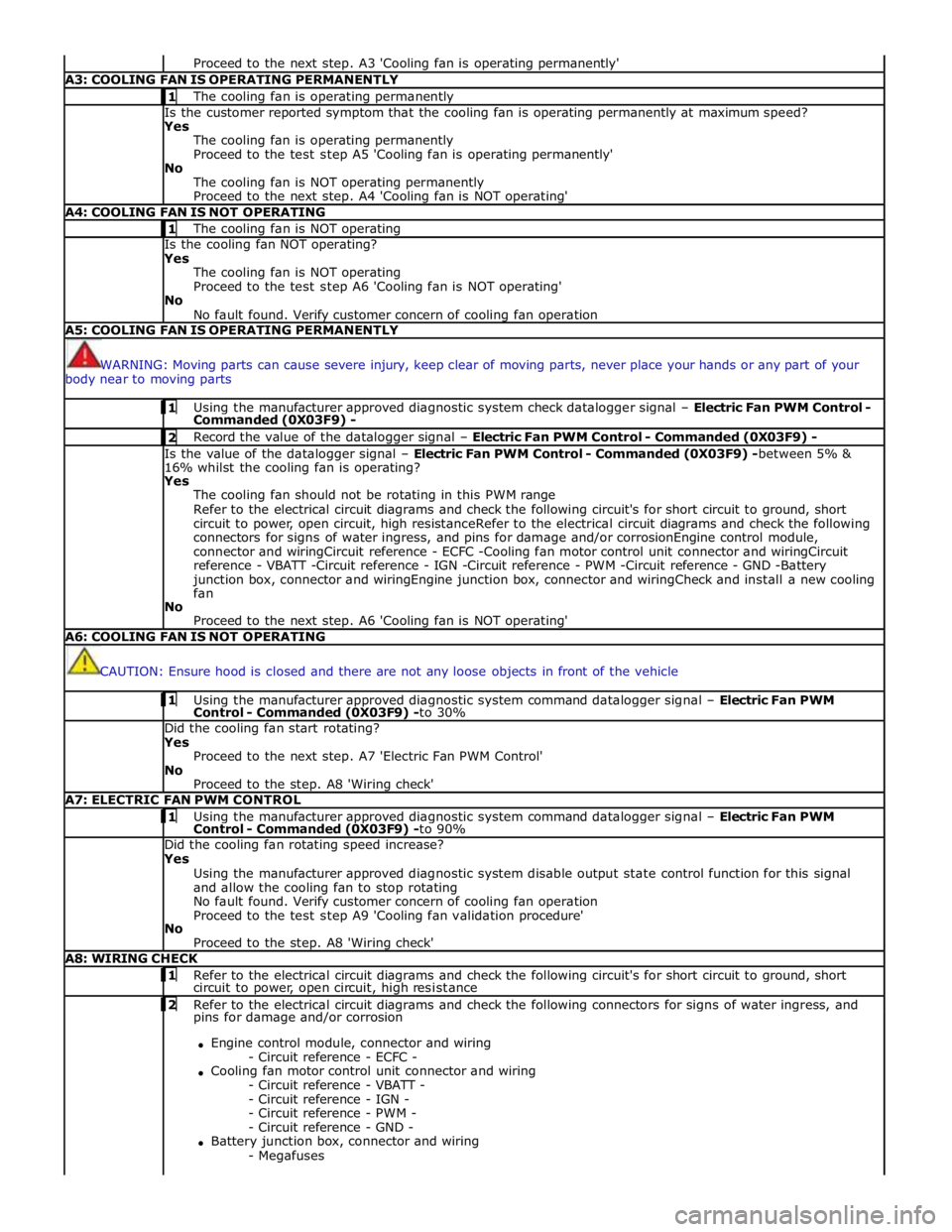
Proceed to the next step. A3 'Cooling fan is operating permanently' A3: COOLING FAN IS OPERATING PERMANENTLY 1 The cooling fan is operating permanently Is the customer reported symptom that the cooling fan is operating permanently at maximum speed?
Yes
The cooling fan is operating permanently
Proceed to the test step A5 'Cooling fan is operating permanently'
No
The cooling fan is NOT operating permanently
Proceed to the next step. A4 'Cooling fan is NOT operating' A4: COOLING FAN IS NOT OPERATING 1 The cooling fan is NOT operating Is the cooling fan NOT operating?
Yes
The cooling fan is NOT operating
Proceed to the test step A6 'Cooling fan is NOT operating'
No
No fault found. Verify customer concern of cooling fan operation A5: COOLING FAN IS OPERATING PERMANENTLY
WARNING: Moving parts can cause severe injury, keep clear of moving parts, never place your hands or any part of your
body near to moving parts 1 Using the manufacturer approved diagnostic system check datalogger signal – Electric Fan PWM Control - Commanded (0X03F9) - 2 Record the value of the datalogger signal – Electric Fan PWM Control - Commanded (0X03F9) - Is the value of the datalogger signal – Electric Fan PWM Control - Commanded (0X03F9) -between 5% &
16% whilst the cooling fan is operating?
Yes
The cooling fan should not be rotating in this PWM range
Refer to the electrical circuit diagrams and check the following circuit's for short circuit to ground, short
circuit to power, open circuit, high resistanceRefer to the electrical circuit diagrams and check the following
connectors for signs of water ingress, and pins for damage and/or corrosionEngine control module,
connector and wiringCircuit reference - ECFC -Cooling fan motor control unit connector and wiringCircuit
reference - VBATT -Circuit reference - IGN -Circuit reference - PWM -Circuit reference - GND -Battery
junction box, connector and wiringEngine junction box, connector and wiringCheck and install a new cooling
fan
No
Proceed to the next step. A6 'Cooling fan is NOT operating' A6: COOLING FAN IS NOT OPERATING
CAUTION: Ensure hood is closed and there are not any loose objects in front of the vehicle 1 Using the manufacturer approved diagnostic system command datalogger signal – Electric Fan PWM Control - Commanded (0X03F9) -to 30% Did the cooling fan start rotating?
Yes
Proceed to the next step. A7 'Electric Fan PWM Control'
No
Proceed to the step. A8 'Wiring check' A7: ELECTRIC FAN PWM CONTROL 1 Using the manufacturer approved diagnostic system command datalogger signal – Electric Fan PWM Control - Commanded (0X03F9) -to 90% Did the cooling fan rotating speed increase?
Yes
Using the manufacturer approved diagnostic system disable output state control function for this signal
and allow the cooling fan to stop rotating
No fault found. Verify customer concern of cooling fan operation
Proceed to the test step A9 'Cooling fan validation procedure'
No
Proceed to the step. A8 'Wiring check' A8: WIRING CHECK 1 Refer to the electrical circuit diagrams and check the following circuit's for short circuit to ground, short circuit to power, open circuit, high resistance 2 Refer to the electrical circuit diagrams and check the following connectors for signs of water ingress, and pins for damage and/or corrosion
Engine control module, connector and wiring
- Circuit reference - ECFC -
Cooling fan motor control unit connector and wiring
- Circuit reference - VBATT -
- Circuit reference - IGN -
- Circuit reference - PWM -
- Circuit reference - GND -
Battery junction box, connector and wiring
- Megafuses
Page 1170 of 3039
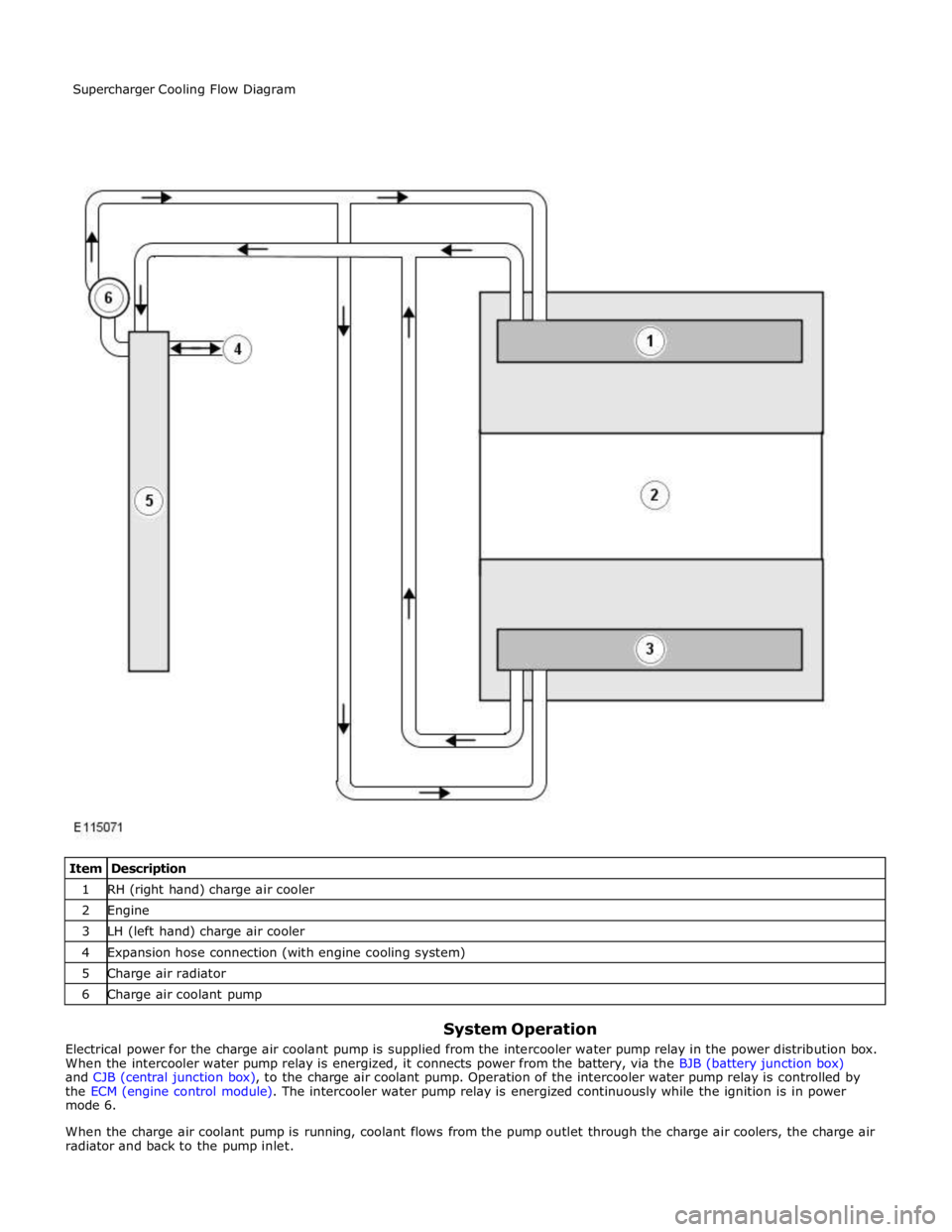
1 RH (right hand) charge air cooler 2 Engine 3 LH (left hand) charge air cooler 4 Expansion hose connection (with engine cooling system) 5 Charge air radiator 6 Charge air coolant pump
System Operation
Electrical power for the charge air coolant pump is supplied from the intercooler water pump relay in the power distribution box.
When the intercooler water pump relay is energized, it connects power from the battery, via the BJB (battery junction box)
and CJB (central junction box), to the charge air coolant pump. Operation of the intercooler water pump relay is controlled by
the ECM (engine control module). The intercooler water pump relay is energized continuously while the ignition is in power
mode 6.
When the charge air coolant pump is running, coolant flows from the pump outlet through the charge air coolers, the charge air
radiator and back to the pump inlet. Supercharger Cooling Flow Diagram
Page 1171 of 3039
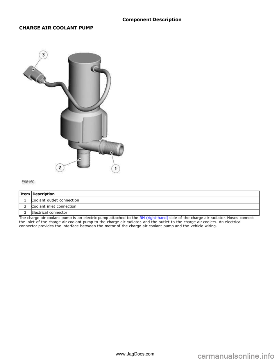
1 Coolant outlet connection 2 Coolant inlet connection 3 Electrical connector The charge air coolant pump is an electric pump attached to the RH (right-hand) side of the charge air radiator. Hoses connect
the inlet of the charge air coolant pump to the charge air radiator, and the outlet to the charge air coolers. An electrical
connector provides the interface between the motor of the charge air coolant pump and the vehicle wiring. www.JagDocs.com
Page 1187 of 3039
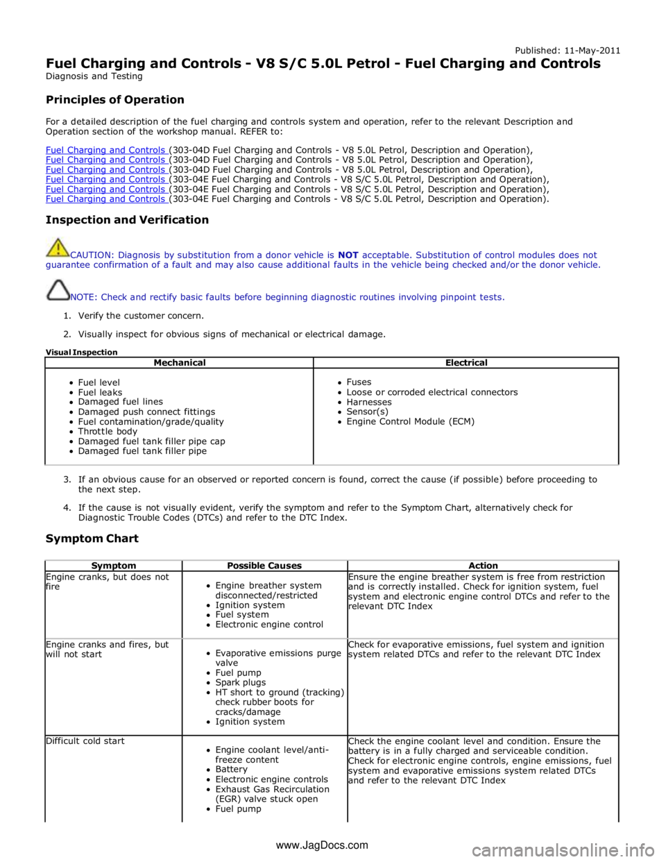
Published: 11-May-2011
Fuel Charging and Controls - V8 S/C 5.0L Petrol - Fuel Charging and Controls
Diagnosis and Testing
Principles of Operation
For a detailed description of the fuel charging and controls system and operation, refer to the relevant Description and
Operation section of the workshop manual. REFER to:
Fuel Charging and Controls (303-04D Fuel Charging and Controls - V8 5.0L Petrol, Description and Operation), Fuel Charging and Controls (303-04D Fuel Charging and Controls - V8 5.0L Petrol, Description and Operation), Fuel Charging and Controls (303-04D Fuel Charging and Controls - V8 5.0L Petrol, Description and Operation), Fuel Charging and Controls (303-04E Fuel Charging and Controls - V8 S/C 5.0L Petrol, Description and Operation), Fuel Charging and Controls (303-04E Fuel Charging and Controls - V8 S/C 5.0L Petrol, Description and Operation), Fuel Charging and Controls (303-04E Fuel Charging and Controls - V8 S/C 5.0L Petrol, Description and Operation).
Inspection and Verification
CAUTION: Diagnosis by substitution from a donor vehicle is NOT acceptable. Substitution of control modules does not
guarantee confirmation of a fault and may also cause additional faults in the vehicle being checked and/or the donor vehicle.
NOTE: Check and rectify basic faults before beginning diagnostic routines involving pinpoint tests.
1. Verify the customer concern.
2. Visually inspect for obvious signs of mechanical or electrical damage.
Visual Inspection
Mechanical Electrical
Fuel level
Fuel leaks
Damaged fuel lines
Damaged push connect fittings
Fuel contamination/grade/quality
Throttle body
Damaged fuel tank filler pipe cap
Damaged fuel tank filler pipe
Fuses
Loose or corroded electrical connectors
Harnesses
Sensor(s)
Engine Control Module (ECM)
3. If an obvious cause for an observed or reported concern is found, correct the cause (if possible) before proceeding to
the next step.
4. If the cause is not visually evident, verify the symptom and refer to the Symptom Chart, alternatively check for
Diagnostic Trouble Codes (DTCs) and refer to the DTC Index.
Symptom Chart
Symptom Possible Causes Action Engine cranks, but does not
fire
Engine breather system
disconnected/restricted
Ignition system
Fuel system
Electronic engine control Ensure the engine breather system is free from restriction
and is correctly installed. Check for ignition system, fuel
system and electronic engine control DTCs and refer to the
relevant DTC Index Engine cranks and fires, but
will not start
Evaporative emissions purge
valve
Fuel pump
Spark plugs
HT short to ground (tracking)
check rubber boots for
cracks/damage
Ignition system Check for evaporative emissions, fuel system and ignition
system related DTCs and refer to the relevant DTC Index Difficult cold start
Engine coolant level/anti-
freeze content
Battery
Electronic engine controls
Exhaust Gas Recirculation
(EGR) valve stuck open
Fuel pump Check the engine coolant level and condition. Ensure the
battery is in a fully charged and serviceable condition.
Check for electronic engine controls, engine emissions, fuel
system and evaporative emissions system related DTCs
and refer to the relevant DTC Index www.JagDocs.com