2010 JAGUAR XFR Can bus
[x] Cancel search: Can busPage 2619 of 3039

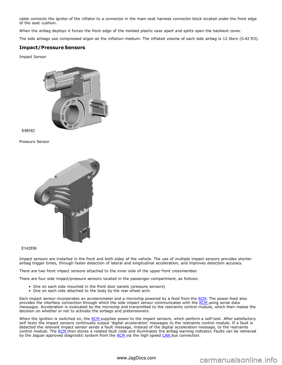
provides the interface connection through which the side impact sensor communicates with the RCM using serial data messages. Acceleration is evaluated by the microchip and transmitted to the restraints control module, which then makes the
decision on whether or not to activate the airbags and pretensioners.
When the ignition is switched on, the RCM supplies power to the impact sensors, which perform a self-test. After satisfactory self tests the impact sensors continually output 'digital acceleration' messages to the restraints control module. If a fault is
detected the relevant impact sensor sends a fault message, instead of the digital acceleration message, to the restraints
control module. The RCM then stores a related fault code and illuminates the airbag warning indicator. Faults can be retrieved by the Jaguar approved diagnostic system from the RCM via the high speed CAN bus connection. www.JagDocs.com
Page 2621 of 3039

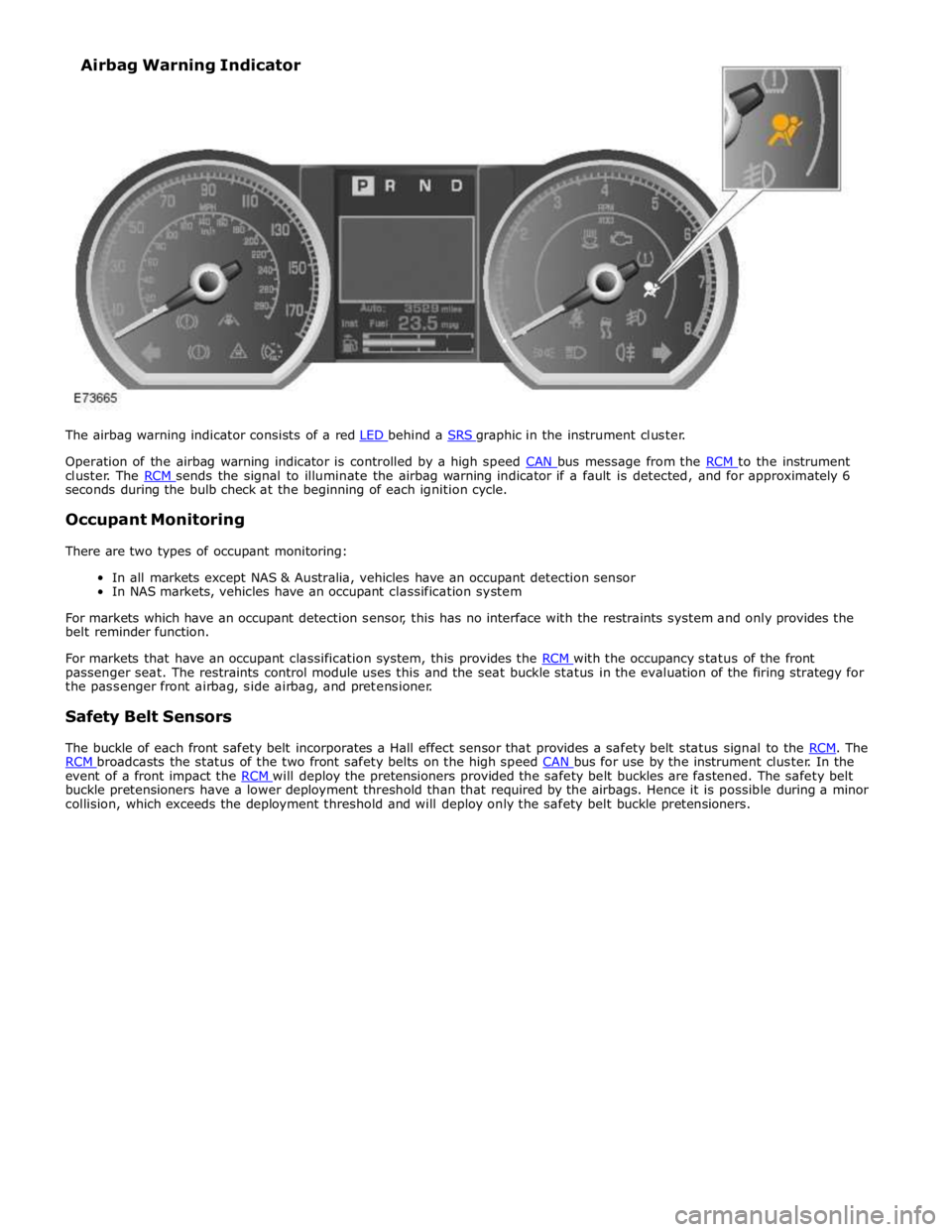
Operation of the airbag warning indicator is controlled by a high speed CAN bus message from the RCM to the instrument cluster. The RCM sends the signal to illuminate the airbag warning indicator if a fault is detected, and for approximately 6 seconds during the bulb check at the beginning of each ignition cycle.
Occupant Monitoring
There are two types of occupant monitoring:
In all markets except NAS & Australia, vehicles have an occupant detection sensor
In NAS markets, vehicles have an occupant classification system
For markets which have an occupant detection sensor, this has no interface with the restraints system and only provides the
belt reminder function.
For markets that have an occupant classification system, this provides the RCM with the occupancy status of the front passenger seat. The restraints control module uses this and the seat buckle status in the evaluation of the firing strategy for
the passenger front airbag, side airbag, and pretensioner.
Safety Belt Sensors
The buckle of each front safety belt incorporates a Hall effect sensor that provides a safety belt status signal to the RCM. The RCM broadcasts the status of the two front safety belts on the high speed CAN bus for use by the instrument cluster. In the event of a front impact the RCM will deploy the pretensioners provided the safety belt buckles are fastened. The safety belt buckle pretensioners have a lower deployment threshold than that required by the airbags. Hence it is possible during a minor
collision, which exceeds the deployment threshold and will deploy only the safety belt buckle pretensioners. Airbag Warning Indicator
Page 2629 of 3039

Supplemental Restraint System - Clockspring
Removal and Installation Published: 11-May-2011
Removal
WARNINGS:
Always wear safety glasses when repairing an air bag supplemental restraint system (SRS) vehicle and when handling an
air bag module.
Carry a live air bag module with the air bag and trim cover pointed away from your body. This will reduce the risk of injury
in the event of an accidental deployment. Failure to follow this instruction may result in personal injury.
Do not set a live air bag module down with the trim cover face down. Failure to follow this instruction may result in
personal injury.
After deployment, the air bag surface can contain deposits of sodium hydroxide, a product of the gas generant
combustion that is irritating to the skin. Wash your hands with soap and water afterwards. Failure to follow this instruction
may result in personal injury.
Never probe the connectors on the air bag module. Doing so may result in air bag deployment, which may result in
personal injury. Failure to follow this instruction may result in personal injury.
Air bag modules with discolored or damaged trim covers must be replaced, not repainted.
Vehicle sensor orientation is critical for correct system operation. If a vehicle equipped with an air bag supplemental
restraint system (SRS) is involved in a collision, inspect the sensor mounting bracket and wiring pigtail for deformation. If
damaged, replace the sensor whether or not the air bag is deployed.
To avoid accidental deployment and possible personal injury, the backup power supply must be depleted before repairing
or replacing any air bag supplemental restraint system (SRS) components. To deplete the backup power supply energy,
disconnect the battery ground cable and wait one minute. Failure to follow this instruction may result in personal injury.
CAUTION: Make sure the wheels are in the straight-ahead position. Failure to follow this instruction may result in
damage to the component.
NOTE: Removal steps in this procedure may contain installation details.
1. Make the SRS system safe.
Refer to: Standard Workshop Practices (100-00 General Information, Description and Operation).
2. CAUTIONS:
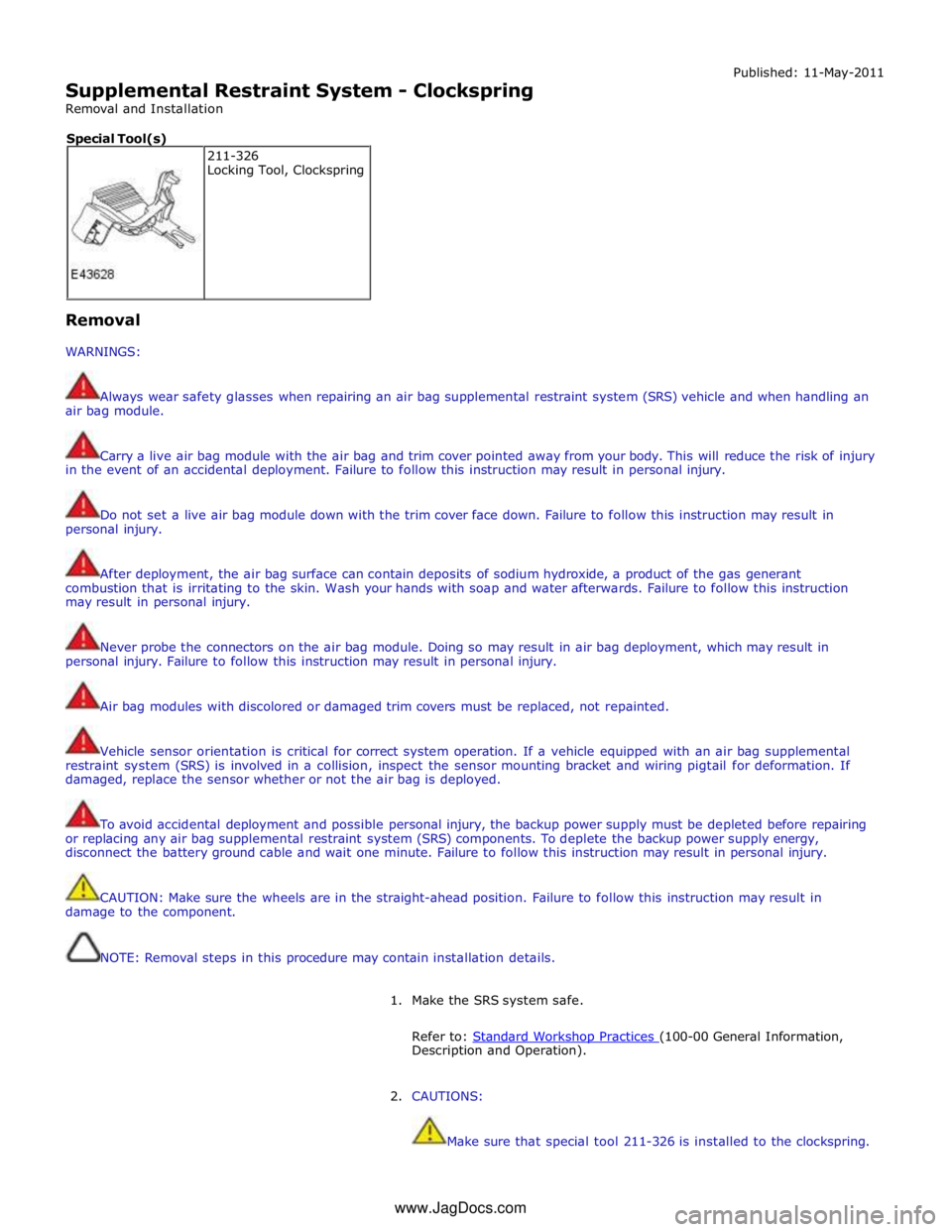
Make sure that special tool 211-326 is installed to the clockspring. 211-326
Locking Tool, Clockspring Special Tool(s)
www.JagDocs.com
Page 2683 of 3039

Published: 11-May-2011
Pedestrian Protection System - Pedestrian Protection System - System
Operation and Component Description
Description and Operation
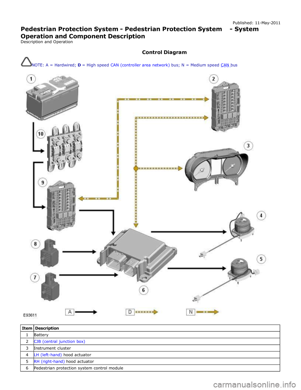
Control Diagram
NOTE: A = Hardwired; D = High speed CAN (controller area network) bus; N = Medium speed CAN bus
Item Description 1 Battery 2 CJB (central junction box) 3 Instrument cluster 4 LH (left-hand) hood actuator 5 RH (right-hand) hood actuator 6 Pedestrian protection system control module
Page 2684 of 3039

7 RH accelerometer 8 LH accelerometer 9 RJB (rear junction box) 10 BJB (battery junction box)
System Operation
The pedestrian protection system is operational when the vehicle is traveling at speeds between approximately 20 km/h (12.4
mph) and 45 km/h (28 mph). A vehicle speed signal is received by the pedestrian protection system control module over the
high speed CAN bus.
The system is able to determine if contact is made with a pedestrian or another object, such as a traffic cone, using signals
from accelerometers mounted behind the front bumper. When the system determines contact is made with a pedestrian it fires
the actuators to lift the rear of the hood approximately 130 mm within 35 ms of the 'fire' signal.
When an impact condition is registered, the pedestrian protection system control module outputs an impact signal on the high
speed CAN bus. This signal is used by the RJB to initiate the hazard warning lamps. If this occurs, the hazard warning lamp switch is disabled for the remainder of the current ignition cycle.
If the pedestrian protection system control module detects a fault with the system, it outputs a message on the high speed
CAN bus to the instrument cluster message center. On receipt of this, the message center will display the message 'CHECK PEDESTRIAN SYSTEM'.
The pedestrian protection system control module also stores the VIN (vehicle identification number). If a new control module
is fitted to the vehicle the Jaguar approved diagnostic tool must be used to program the unit with the vehicles VIN.
When the vehicle is delivered from the factory the pedestrian protection system is in a 'safe' plant mode. Normal operating
mode should be activated using the Jaguar approved diagnostic tool during the Pre-Delivery Inspection (PDI) prior to delivery
to the customer. For additional information, refer to the PDI manual.
If any damage is caused to the front of the vehicle, be it cosmetic or structural, repairs must be carried out in line with the
processes contained in the workshop manual. Failure to carry out the correct repair process could compromise operation of the
pedestrian protection system. Refer to GTR for the latest information.
The vehicle must be left for 1 minute after disconnecting the battery before any work can be carried out on the pedestrian
protection system.
Failure Mode Detection
In service, if any fault is detected, or any part of the system is recognized as not being present, the message center displays
the warning 'Check Pedestrian System'.
The bonnet deployment actuators are non-serviceable components, and if they must be replaced due to a fault, or due to
having been deployed, or following any other accident, their barcode labels must be read and recorded in the service database
against the vehicle VIN for security purposes.
After deployment of the pedestrian protection system, the vehicle must be stopped as soon as it is safe to do so. The hazard
warning lamps will be activated and can only be switched off by pressing the engine START/STOP button to turn the engine off
and on again. A warning message 'CHECK PEDESTRIAN SYSTEM' will appear on the message center and the vehicle should be
transported to the nearest dealer/authorised repairer. The vehicle must not be driven when the bonnet has been deployed.
NOTE: If the warning message 'CHECK PEDESTRIAN SYSTEM' appears in the message center when the bonnet has not
been deployed, the vehicle should be taken to the nearest dealer/authorised repairer immediately. It can be driven.
If any significant damage occurs to the front bumper it should be inspected by a dealer/authorised repairer as soon as
possible.
CONTROL MODULE Component Description
The control module is mounted below the hood release lever behind the side trim in the left hand front footwell.
The deployment signal is received from the pedestrian protection system control module. The second-generation system
adopted for XF is all-new to Jaguar and, although similar, differs from that introduced on XK by having an accelerometer-based
sensing system rather than a contact-sensing system. The accelerometer-based system is supplied by Bosch. Mounted very
close to the skin of the bumper, it examines the characteristics of vibration waves caused by impact. Its response time is
quicker, because it does not rely on the front of the bumper being loaded. It uses the 'saved' time to make more complex
decisions, and so has fewer error states. The speed of vehicle and the length of the bonnet define the time available to get
the bonnet into its deployed and stabilized position. It is possible, therefore, to create a time-line counting back from the
predicted moment of head impact to the time when the deployment signals need to be sent. That in turn defines a time from
first contact to decision time.
www.JagDocs.com