2010 JAGUAR XFR Can bus
[x] Cancel search: Can busPage 2315 of 3039
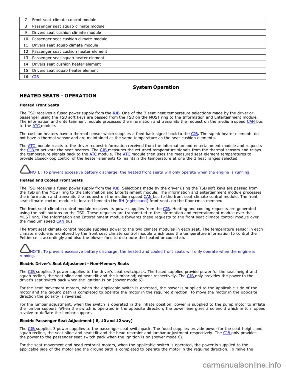
7 Front seat climate control module 8 Passenger seat squab climate module 9 Drivers seat cushion climate module 10 Passenger seat cushion climate module 11 Drivers seat squab climate module 12 Passenger seat cushion heater element 13 Passenger seat squab heater element 14 Drivers seat cushion heater element 15 Drivers seat squab heater element 16 CJB
HEATED SEATS - OPERATION
Heated Front Seats System Operation
The TSD receives a fused power supply from the RJB. One of the 3 seat heat temperature selections made by the driver or passenger using the TSD soft keys are passed from the TSD on the MOST ring to the Information and Entertainment module.
The information and entertainment module processes the information and transmits the request on the medium speed CAN bus to the ATC module.
The cushion heaters have a thermal sensor which supplies a feed back signal back to the CJB. The squab heater elements do not have a thermal sensor and are maintained at the same temperature as the seat cushion elements.
The ATC module reacts to the driver request information received from the information and entertainment module and requests the CJB to activate the seat heaters. The CJB measures the returned temperature signals from the thermal sensors and relays the temperature signals back to the ATC module. The ATC module then uses the measured seat element temperatures to provide closed-loop control of the heater elements to maintain the temperature at one the 3 heat ranges selected.
NOTE: To prevent excessive battery discharge, the heated front seats will only operate when the engine is running.
Heated and Cooled Front Seats
The TSD receives a fused power supply from the RJB. Selections made by the driver using the TSD soft keys are passed from the TSD on the MOST ring to the Information and Entertainment module. The information and entertainment module processes
the information and transmits the request on the medium speed CAN bus to the front seat climate control module. The front seat climate control module is located beneath the RH (right-hand) front seat, on the floor cross member.
The front seat climate control module receives its power supplies from the CJB. Heating and cooling requests are generated using the soft buttons on the TSD. These requests are transmitted to the information and entertainment module over the
MOST ring. The Information and Entertainment module forwards these requests to the front seat climate control module over
the medium speed CAN bus.
The front seat climate control module supplies power to the two climate modules in each seat. The temperature sensor in each
climate module is monitored by the front seat climate control module which uses the temperature information to control the
Peltier cells accordingly and also the blower fans to distribute the heated or cooled air.
NOTE: To prevent excessive battery discharge, the heated and cooled front seats will only operate when the engine is
running.
Electric Driver's Seat Adjustment - Non-Memory Seats
The CJB supplies 3 power supplies to the driver's seat switchpack. The fused supplies provide power for the seat height and squab recline, the seat slide and seat tilt and the lumbar adjustment respectively. The CJB only provides the power to the driver's seat switch pack when the ignition is on (power mode 6).
For the seat movement motors, when the applicable switch is operated, the power is supplied to the applicable side of the
motor and the ground path is completed to operate the motor in the required direction. To move the motor in the opposite
direction the polarity is reversed.
For the lumbar adjustment, when the switch is operated in the inflate position, power is supplied to the pump motor to inflate
the lumbar support. When the switch is operated in the opposite direction, the power energizes a solenoid which in turn opens
a valve to deflate the lumbar support.
Electric Passenger Seat Adjustment ( 8, 10 and 12 way)
The CJB supplies 3 power supplies to the passenger seat switchpack. The fused supplies provide power for the seat height and squab recline, the seat slide and seat tilt and the head restraint and lumbar adjustment respectively. The CJB only provides the power to the passenger seat switch pack when the ignition is on (power mode 6).
For the seat movement and head restraint motors, when the applicable switch is operated, the power is supplied to the
applicable side of the motor and the ground path is completed to operate the motor in the required direction. To move the
Page 2316 of 3039
supplies provide power for the movement motors in addition to the driver's seat switch pack. Power is only supplied to the
driver's seat module and the driver's seat switch pack when the ignition is on (power mode 6).
The driver's seat switch pack is connected to the driver's seat module by a LIN bus for the seat movement switches. Any selection for seat movement generates a message which is passed via the LIN to the driver's seat module. The seat module processes the request and operates the applicable seat function as required using the power supplies from the CJB.
Each seat motor contains a Hall position sensor. The sensor sends a feedback signal to the driver's seat module. The signal is
used for memory store and memory recall functions.
The lumbar adjustment switch on the driver's seat switch pack is wired direct to the lumbar pump and solenoids. The switch,
when moved to the inflate position for either the upper or lower inflatable cushion cell, provides a power supply to the lumbar
pump and simultaneously activates the applicable inflate solenoid valve. When the switch is released the pump stops and the
solenoid valve closes trapping the air in the inflatable cushion. When the switch is moved to the deflate position for either the
upper or lower inflatable cushion cell, power is supplied to the applicable deflate solenoid valve which opens to allow the air in
the cushion to escape. When the switch is released, the valve is closed and the remaining air in the cushion is retained.
FRONT SEATS - DESCRIPTION Component Description
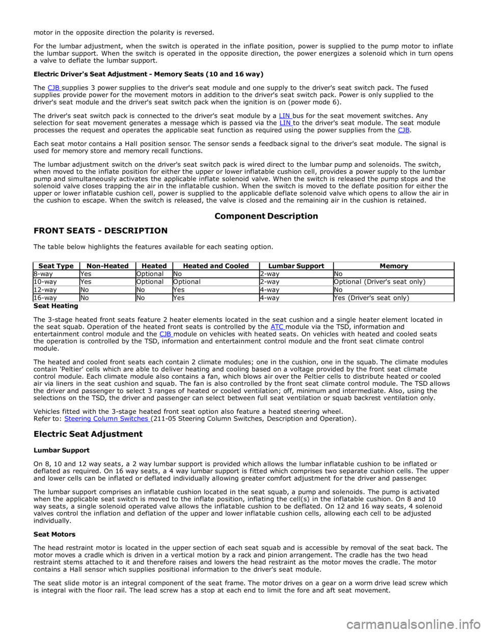
The table below highlights the features available for each seating option.
Seat Type Non-Heated Heated Heated and Cooled Lumbar Support Memory 8-way Yes Optional No 2-way No 10-way Yes Optional Optional 2-way Optional (Driver's seat only) 12-way No No Yes 4-way No 16-way No No Yes 4-way Yes (Driver's seat only) Seat Heating
The 3-stage heated front seats feature 2 heater elements located in the seat cushion and a single heater element located in
the seat squab. Operation of the heated front seats is controlled by the ATC module via the TSD, information and entertainment control module and the CJB module on vehicles with heated seats. On vehicles with heated and cooled seats the operation is controlled by the TSD, information and entertainment control module and the front seat climate control
module.
The heated and cooled front seats each contain 2 climate modules; one in the cushion, one in the squab. The climate modules
contain 'Peltier' cells which are able to deliver heating and cooling based on a voltage provided by the front seat climate
control module. Each climate module also contains a fan, which blows air over the Peltier cells to distribute heated or cooled
air via liners in the seat cushion and squab. The fan is also controlled by the front seat climate control module. The TSD allows
the driver and passenger to select 3 ranges of heated or cooled ventilation; off, minimum and intermediate. Also, using the
selections on the TSD, the driver and passenger can select between full seat ventilation or squab backrest ventilation only.
Vehicles fitted with the 3-stage heated front seat option also feature a heated steering wheel.
Refer to: Steering Column Switches (211-05 Steering Column Switches, Description and Operation).
Electric Seat Adjustment
Lumbar Support
On 8, 10 and 12 way seats, a 2 way lumbar support is provided which allows the lumbar inflatable cushion to be inflated or
deflated as required. On 16 way seats, a 4 way lumbar support is fitted which comprises two separate cushion cells. The upper
and lower cells can be inflated or deflated individually allowing greater comfort adjustment for the driver and passenger.
The lumbar support comprises an inflatable cushion located in the seat squab, a pump and solenoids. The pump is activated
when the applicable seat switch is moved to the inflate position, inflating the cell(s) in the inflatable cushion. On 8 and 10
way seats, a single solenoid operated valve allows the inflatable cushion to be deflated. On 12 and 16 way seats, 4 solenoid
valves control the inflation and deflation of the upper and lower inflatable cushion cells, allowing each cell to be adjusted
individually.
Seat Motors
The head restraint motor is located in the upper section of each seat squab and is accessible by removal of the seat back. The
motor moves a cradle which is driven in a vertical motion by a rack and pinion arrangement. The cradle has the two head
restraint stems attached to it and therefore raises and lowers the head restraint as the motor moves the cradle. The motor
contains a Hall sensor which supplies positional information to the driver's seat module.
The seat slide motor is an integral component of the seat frame. The motor drives on a gear on a worm drive lead screw which
is integral with the floor rail. The lead screw has a stop at each end to limit the fore and aft seat movement.
Page 2329 of 3039
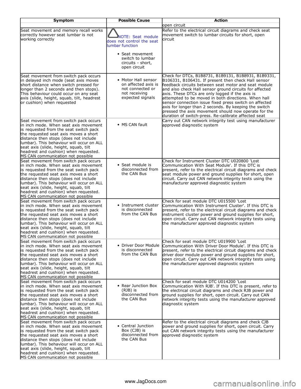
Symptom Possible Cause Action open circuit Seat movement and memory recall works
correctly however seat lumbar is not
working correctly
NOTE: Seat module
does not control the seat
lumbar function
Seat movement
switch to lumbar
circuits - short,
open circuit Refer to the electrical circuit diagrams and check seat
movement switch to lumbar circuits for short, open
circuit Seat movement from switch pack occurs
in delayed inch mode (seat axis moves
short distance when switch pressed for
longer than 2 seconds and then stops). This behaviour could occur on any seat
axis (slide, height, squab, tilt, headrest
or cushion) when requested
Motor Hall sensor
on affected axis is
not connected or
not receiving
expected signals Check for DTCs, B1B8731, B1B9131, B1B8931, B1B9331,
B106331, B106431. If present then check Hall sensor
feedback circuits between seat motor and seat module
and also check Hall sensor ground circuits for affected
axis. These DTCs are only logged if the axis is
attempted to be moved in both directions. When hall
sensor connection issue fixed press switch on affected
axis for longer than 2 seconds. By keeping the switch
pressed the axis movement should now operate for the
duration of switch-press. Re-calibrate affected seat Seat movement from switch pack occurs
in inch mode. When seat axis movement
is requested from the seat switch pack
the requested seat axis moves a short
distance then stops (does not include
lumbar). This behaviour will occur on ALL
seat axis (slide, height, squab, tilt
headrest and cushion) when requested.
MS CAN communication not possible
MS CAN fault Carry out CAN network integrity test using manufacturer
approved diagnostic system Seat movement from switch pack occurs
in inch mode. When seat axis movement
is requested from the seat switch pack
the requested seat axis moves a short
distance then stops (does not include
lumbar). This behaviour will occur on ALL
seat axis (slide, height, squab, tilt
headrest and cushion) when requested.
MS CAN communication not possible
Seat module is
disconnected from
the CAN Bus Check for Instrument Cluster DTC U020800 'Lost
Communication With Seat Module'. If this DTC is
present, refer to the electrical circuit diagrams and check
seat module power and ground supplies for short, open
circuit. Carry out CAN network integrity tests using the
manufacturer approved diagnostic system Seat movement from switch pack occurs
in inch mode. When seat axis movement
is requested from the seat switch pack
the requested seat axis moves a short
distance then stops (does not include
lumbar). This behaviour will occur on ALL
seat axis (slide, height, squab, tilt
headrest and cushion) when requested.
MS CAN communication not possible
Instrument cluster
is disconnected
from the CAN Bus Check for seat module DTC U015500 'Lost
Communication With Instrument Cluster'. If this DTC is
present, refer to the electrical circuit diagrams and check
instrument cluster power and ground supplies for short,
open circuit. Carry out CAN network integrity tests using
the manufacturer approved diagnostic system Seat movement from switch pack occurs
in inch mode. When seat axis movement
is requested from the seat switch pack
the requested seat axis moves a short
distance then stops (does not include
lumbar). This behaviour will occur on ALL
seat axis (slide, height, squab, tilt
headrest and cushion) when requested.
MS CAN communication not possible
Driver Door Module
is disconnected
from the CAN Bus Check for seat module DTC U019900 'Lost
Communication With Driver Door Module'. If this DTC is
present, refer to the electrical circuit diagrams and check
driver door module power and ground supplies for short,
open circuit. Carry out CAN network integrity tests using
the manufacturer approved diagnostic system Seat movement from switch pack occurs
in inch mode. When seat axis movement
is requested from the seat switch pack
the requested seat axis moves a short
distance then stops (does not include
lumbar). This behaviour will occur on ALL
seat axis (slide, height, squab, tilt
headrest and cushion) when requested.
MS CAN communication not possible
Rear Junction Box
(RJB) is
disconnected from
the CAN Bus Check for seat module DTC U014200 'Lost
Communication With RJB'. If this DTC is present, refer to
the electrical circuit diagrams and check RJB power and
ground supplies for short, open circuit. Carry out CAN
network integrity tests using the manufacturer approved
diagnostic system Seat movement from switch pack occurs
in inch mode. When seat axis movement
is requested from the seat switch pack
the requested seat axis moves a short
distance then stops (does not include
lumbar). This behaviour will occur on ALL
seat axis (slide, height, squab, tilt
headrest and cushion) when requested.
MS CAN communication not possible
Central Junction
Box (CJB) is
disconnected from
the CAN Bus Refer to the electrical circuit diagrams and check CJB
power and ground supplies for short, open circuit. Carry
out CAN network integrity tests using the manufacturer
approved diagnostic system www.JagDocs.com
Page 2333 of 3039

DTC Description Possible Cause Action B1C0024
Seat Recline Up
Switch
Signal stuck high Check for a stuck switch. Refer to the electrical circuit
diagrams and check driver seat switch pack to seat
module LIN circuit for short, open circuit and seat
recline up circuit for short to ground B1C0124
Seat Recline Down
Switch
Signal stuck high Check for a stuck switch. Refer to the electrical circuit
diagrams and check driver seat switch pack to seat
module LIN circuit for short, open circuit and check seat
recline down circuit for short to ground B1C0224 Memory Store Switch
Signal stuck high Check for a stuck switch. Refer to the electrical circuit
diagrams and check driver seat switch pack to seat
module LIN circuit for short, open circuit B1C0324 Memory #1 Switch
Signal stuck high Check for a stuck switch. Refer to the electrical circuit
diagrams and check driver seat switch pack to seat
module LIN circuit for short, open circuit B1C0424 Memory #2 Switch
Signal stuck high Check for a stuck switch. Refer to the electrical circuit
diagrams and check driver seat switch pack to seat
module LIN circuit for short, open circuit B1C0524 Memory #3 Switch
Signal stuck high Check for a stuck switch. Refer to the electrical circuit
diagrams and check driver seat switch pack to seat
module LIN circuit for short, open circuit U001088
Medium speed Can
communication Bus
Bus off Carry out any pinpoint tests associated with this DTC
using the manufacturer approved diagnostic system.
Refer to the electrical circuit diagrams and check CAN
network to climate controlled seat module for short, open circuit U014000
Lost communication
with CJB
Lost communication with CJB Carry out any pinpoint tests associated with this DTC
using the manufacturer approved diagnostic system.
Check CJB for related DTCs and refer to the relevant
DTC Index U014200
Lost communication
with RJB
Lost communication with RJB Carry out any pinpoint tests associated with this DTC
using the manufacturer approved diagnostic system.
Check RJB for related DTCs and refer to the relevant
DTC Index U015500
Lost
communications
with instrument
cluster
Lost communications with
instrument cluster Carry out any pinpoint tests associated with this DTC
using the manufacturer approved diagnostic system.
Refer to the electrical circuit diagrams and check CAN
network to climate controlled seat module and
instrument cluster for short, open circuit U019900
Lost communication
with Driver Door
Module (DDM)
Lost communication with DDM Carry out any pinpoint tests associated with this DTC
using the manufacturer approved diagnostic system U030000
Internal control
module software
incompatibility
Invalid configuration message is
received Re-configure the RJB using the manufacturer approved
diagnostic system. Clear the DTC and retest. If the DTC
is still logged suspect the DSM/PSM, refer to the new
module installation note at the top of the DTC Index U1A1449
CAN Initialisation
failure
Internal electronic failure Install a new DSM, refer to the new module installation
note at the top of the DTC Index U1A4C68
Build/end of line
mode active
Manufacturing mode has not
been removed Place DSM in to customer mode using manufacturer
approved diagnostic system U300049 Control module
Internal electronic failure Install a new DSM, refer to the new module installation
note at the top of the DTC Index U300055
Stored vehicle
configuration data
does not match
Incorrect car configuration data
received Re-configure the RJB using the manufacturer approved
diagnostic system. Clear DTC and re-test. If the DTC
remains suspect the DSM, refer to the new module
installation note at the top of the DTC Index U300087 Control Module
Missing message Re-configure the RJB using the manufacturer approved
diagnostic system. Check DSM for DTCs and refer to the
DTC Index. Check CAN network integrity using the
manufacturer approved diagnostic system U300146
Control module
improper shutdown
Calibration/parameter memory
failure Check for DTCs that could indicate power failure to the
module and refer to the DTC Index U300281
Vehicle
Identification
Number (VIN)
Vehicle/component mis-match.
Corrupt VIN data being
transmitted, module previously
installed to other vehicle Install original module, check for DTCs and refer to
relevant DTC Index U300316 Battery Voltage
Circuit voltage below threshold Carry out any pinpoint tests associated with this DTC
using the manufacturer approved diagnostic system
Page 2352 of 3039
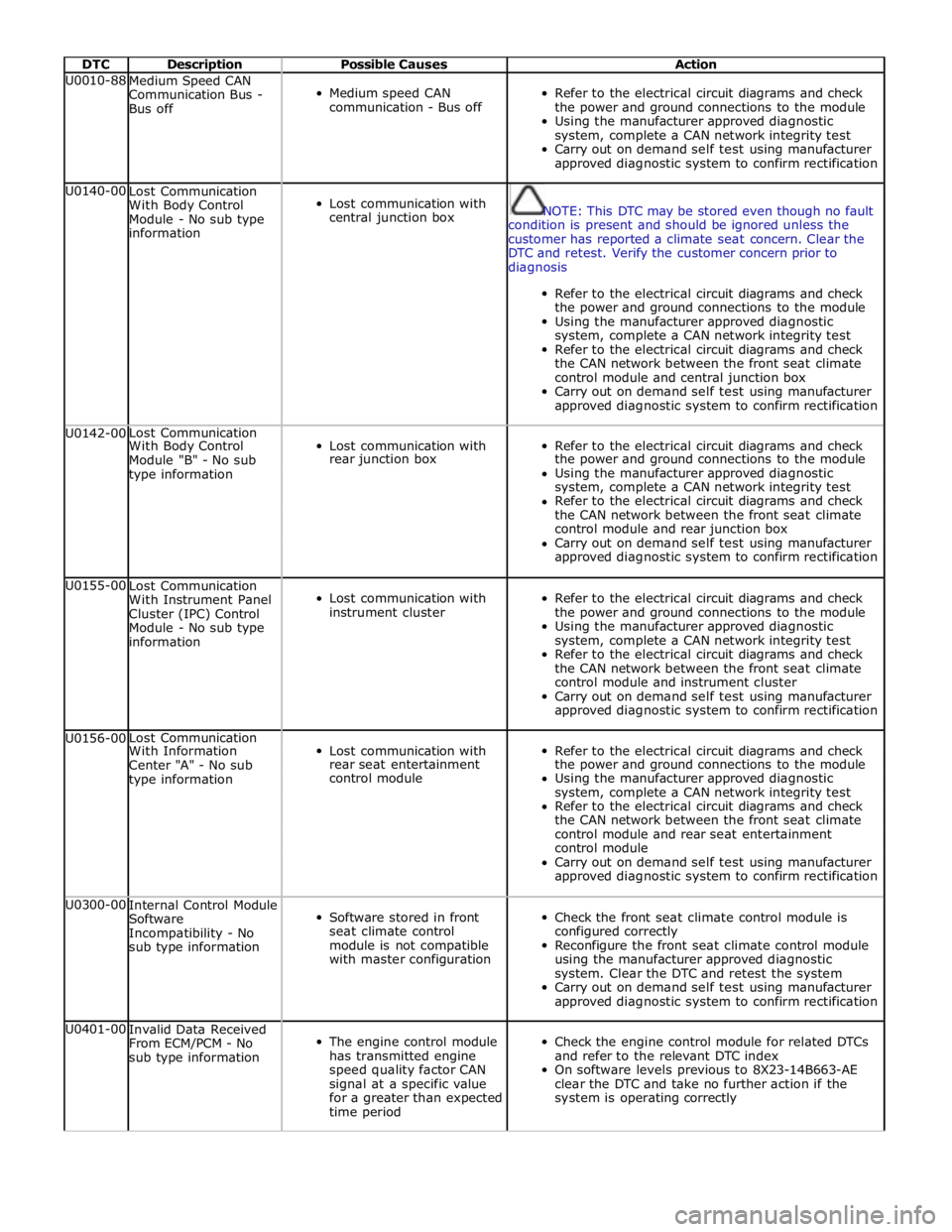
DTC Description Possible Causes Action U0010-88
Medium Speed CAN
Communication Bus -
Bus off
Medium speed CAN
communication - Bus off
Refer to the electrical circuit diagrams and check
the power and ground connections to the module
Using the manufacturer approved diagnostic
system, complete a CAN network integrity test
Carry out on demand self test using manufacturer
approved diagnostic system to confirm rectification U0140-00
Lost Communication
With Body Control
Module - No sub type
information
Lost communication with
central junction box
NOTE: This DTC may be stored even though no fault
condition is present and should be ignored unless the
customer has reported a climate seat concern. Clear the
DTC and retest. Verify the customer concern prior to
diagnosis
Refer to the electrical circuit diagrams and check
the power and ground connections to the module
Using the manufacturer approved diagnostic
system, complete a CAN network integrity test
Refer to the electrical circuit diagrams and check
the CAN network between the front seat climate
control module and central junction box
Carry out on demand self test using manufacturer
approved diagnostic system to confirm rectification U0142-00 Lost Communication
Lost communication with
Refer to the electrical circuit diagrams and check With Body Control Module "B" - No sub rear junction box the power and ground connections to the module type information Using the manufacturer approved diagnostic system, complete a CAN network integrity test Refer to the electrical circuit diagrams and check the CAN network between the front seat climate control module and rear junction box Carry out on demand self test using manufacturer approved diagnostic system to confirm rectification U0155-00
Lost Communication
With Instrument Panel
Cluster (IPC) Control
Module - No sub type
information
Lost communication with
instrument cluster
Refer to the electrical circuit diagrams and check
the power and ground connections to the module
Using the manufacturer approved diagnostic
system, complete a CAN network integrity test
Refer to the electrical circuit diagrams and check
the CAN network between the front seat climate
control module and instrument cluster
Carry out on demand self test using manufacturer
approved diagnostic system to confirm rectification U0156-00 Lost Communication
Lost communication with
Refer to the electrical circuit diagrams and check With Information Center "A" - No sub rear seat entertainment the power and ground connections to the module type information control module Using the manufacturer approved diagnostic system, complete a CAN network integrity test Refer to the electrical circuit diagrams and check the CAN network between the front seat climate control module and rear seat entertainment control module Carry out on demand self test using manufacturer approved diagnostic system to confirm rectification U0300-00
Internal Control Module
Software
Incompatibility - No
sub type information
Software stored in front
seat climate control
module is not compatible
with master configuration
Check the front seat climate control module is
configured correctly
Reconfigure the front seat climate control module
using the manufacturer approved diagnostic
system. Clear the DTC and retest the system
Carry out on demand self test using manufacturer
approved diagnostic system to confirm rectification U0401-00
Invalid Data Received
From ECM/PCM - No
sub type information
The engine control module
has transmitted engine
speed quality factor CAN
signal at a specific value
for a greater than expected
time period
Check the engine control module for related DTCs
and refer to the relevant DTC index
On software levels previous to 8X23-14B663-AE
clear the DTC and take no further action if the
system is operating correctly
Page 2414 of 3039
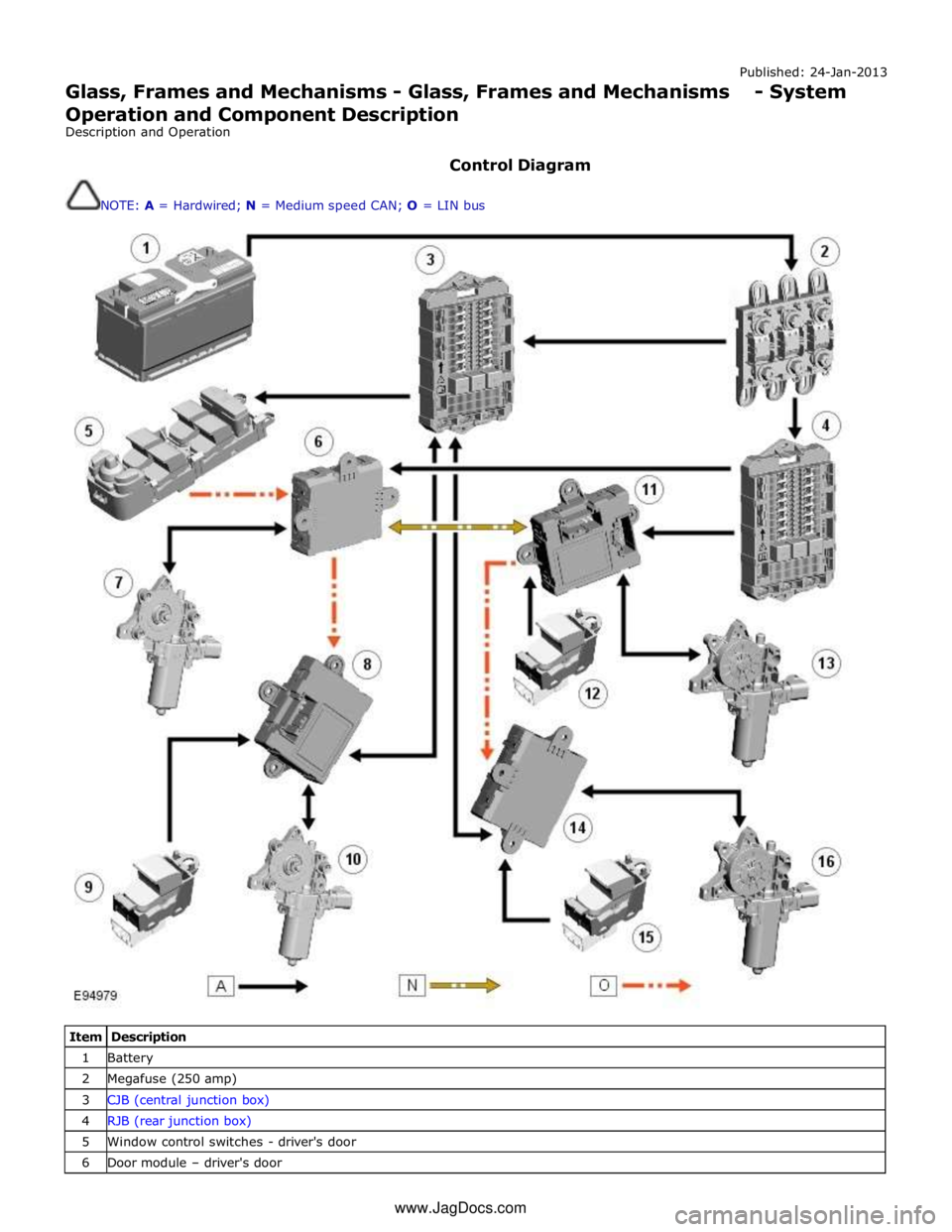
Published: 24-Jan-2013
Glass, Frames and Mechanisms - Glass, Frames and Mechanisms - System
Operation and Component Description
Description and Operation
Control Diagram
NOTE: A = Hardwired; N = Medium speed CAN; O = LIN bus
Item Description 1 Battery 2 Megafuse (250 amp) 3 CJB (central junction box) 4 RJB (rear junction box) 5 Window control switches - driver's door 6 Door module – driver's door www.JagDocs.com
Page 2415 of 3039
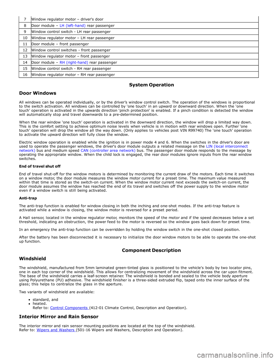
7 Window regulator motor – driver's door 8 Door module – LH (left-hand) rear passenger 9 Window control switch - LH rear passenger 10 Window regulator motor – LH rear passenger 11 Door module – front passenger 12 Window control switches - front passenger 13 Window regulator motor – front passenger 14 Door module – RH (right-hand) rear passenger 15 Window control switch - RH rear passenger 16 Window regulator motor – RH rear passenger
Door Windows System Operation
All windows can be operated individually, or by the driver’s window control switch. The operation of the windows is proportional
to the switch activation. All windows can be controlled by ‘one touch’ in an upward or downward direction. When the ‘one
touch’ operation is activated in the upwards direction ‘pinch protection‘ is enabled. If a pinch condition is detected the window
will automatically stop and travel downwards to a pre-determined position.
When the rear window ‘one touch’ operation is activated in the downward direction, the window will drop a limited way down.
This is the comfort setting to achieve optimum noise levels when vehicle is in motion with rear windows open. Further ‘one
touch’ operation will drop the window all the way down. (Only applies to vehicles post VIN R99740) The ‘one touch’ operation
to activate the upward direction will fully close the window.
Electric window operation is enabled while the ignition is in power mode 4 and 6. When the switches in the driver's door are
used to operate the passenger windows, the driver's door module outputs a related message on the LIN (local interconnect
network) bus and medium speed CAN (controller area network) bus. The passenger door module responds to the message by
operating the appropriate window. When the child lock is engaged, the rear door modules ignore inputs from the rear window
switches.
End of travel shut off
End of travel shut-off for the window motors is determined by monitoring the current draw of the motors. Each time it switches
on a window motor, the door module measures the window motor current for a preset time. The maximum value measured
within that time is stored as the switch-on current. When the window motor current next exceeds the switch-on current, the
door module assumes the window has reached the end of its travel and switches off the power supply to the window motor
even if a window switch is still being activated.
Anti-trap
The anti-trap function is enabled for window closing in both the inching and one-shot modes. If the anti-trap feature is
activated while a window is closing, the window motor is reversed for a preset period.
A Hall sensor, located in the window regulator motor, monitors the speed of the motor and if the speed decreases below a set
threshold, indicating an obstruction, the power feed to the motor is reversed so the window goes back down for preset time.
In an emergency the anti-trap function can be overridden by holding the window switch in the one-shot closed position.
After the battery has been disconnected it is necessary to initialize the door window motors to be able to operate the one-shot
up function.
Windshield Component Description
The windshield, manufactured from 5mm laminated green-tinted glass is positioned to the vehicle's body by two locator pins,
one in each top corner of the windshield. This allows for centralizing movement of the windshield across the car upon fitment.
The base of the windshield carries a leaf-screen retainer. The windshield is bonded and sealed to the vehicle body aperture
using Polyurethane (PU) adhesive. The windshield finisher is a three-sided extruded flip, taped onto the inner surface of the
glass; this helps to centralize the glass in the aperture.
Two variants of windshield are available:
standard, and
heated.
Refer to: Control Components (412-01 Climate Control, Description and Operation).
Interior Mirror and Rain Sensor
The interior mirror and rain sensor mounting positions are located at the top of the windshield.
Refer to: Wipers and Washers (501-16 Wipers and Washers, Description and Operation).
Page 2490 of 3039
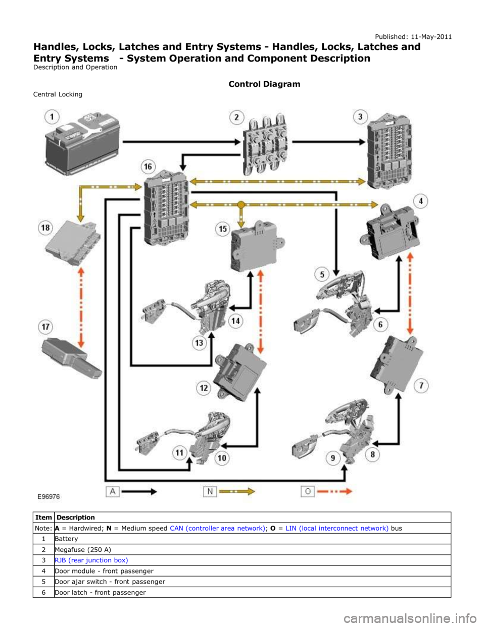
Note: A = Hardwired; N = Medium speed CAN (controller area network); O = LIN (local interconnect network) bus 1 Battery 2 Megafuse (250 A) 3 RJB (rear junction box) 4 Door module - front passenger 5 Door ajar switch - front passenger 6 Door latch - front passenger