2010 JAGUAR XFR ignition
[x] Cancel search: ignitionPage 1181 of 3039
to deliver the correct mass of fuel to the combustion chambers.
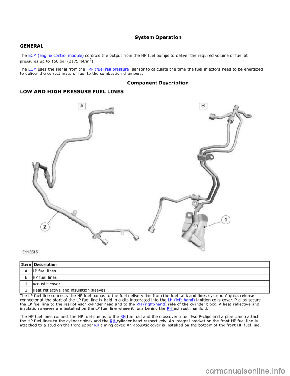
LOW AND HIGH PRESSURE FUEL LINES Component Description
Item Description A LP fuel lines B HP fuel lines 1 Acoustic cover 2 Heat reflective and insulation sleeves The LP fuel line connects the HP fuel pumps to the fuel delivery line from the fuel tank and lines system. A quick release
connector at the start of the LP fuel line is held in a clip integrated into the LH (left-hand) ignition coils cover. P-clips secure
the LP fuel line to the rear of each cylinder head and to the RH (right-hand) side of the cylinder block. A heat reflective and
insulation sleeves are installed on the LP fuel line where it runs behind the RH exhaust manifold.
The HP fuel lines connect the HP fuel pumps to the RH fuel rail and the crossover tube. Two P-clips and a pipe clamp attach the HP fuel lines to the cylinder block and the RH cylinder head respectively. An integral bracket on the front HP fuel line is attached to a stud on the front-upper RH timing cover. An acoustic cover is installed on the bottom of the front HP fuel line.
Page 1187 of 3039
Published: 11-May-2011
Fuel Charging and Controls - V8 S/C 5.0L Petrol - Fuel Charging and Controls
Diagnosis and Testing
Principles of Operation
For a detailed description of the fuel charging and controls system and operation, refer to the relevant Description and
Operation section of the workshop manual. REFER to:
Fuel Charging and Controls (303-04D Fuel Charging and Controls - V8 5.0L Petrol, Description and Operation), Fuel Charging and Controls (303-04D Fuel Charging and Controls - V8 5.0L Petrol, Description and Operation), Fuel Charging and Controls (303-04D Fuel Charging and Controls - V8 5.0L Petrol, Description and Operation), Fuel Charging and Controls (303-04E Fuel Charging and Controls - V8 S/C 5.0L Petrol, Description and Operation), Fuel Charging and Controls (303-04E Fuel Charging and Controls - V8 S/C 5.0L Petrol, Description and Operation), Fuel Charging and Controls (303-04E Fuel Charging and Controls - V8 S/C 5.0L Petrol, Description and Operation).
Inspection and Verification
CAUTION: Diagnosis by substitution from a donor vehicle is NOT acceptable. Substitution of control modules does not
guarantee confirmation of a fault and may also cause additional faults in the vehicle being checked and/or the donor vehicle.
NOTE: Check and rectify basic faults before beginning diagnostic routines involving pinpoint tests.
1. Verify the customer concern.
2. Visually inspect for obvious signs of mechanical or electrical damage.
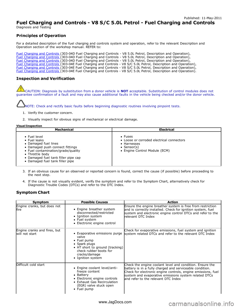
Visual Inspection
Mechanical Electrical
Fuel level
Fuel leaks
Damaged fuel lines
Damaged push connect fittings
Fuel contamination/grade/quality
Throttle body
Damaged fuel tank filler pipe cap
Damaged fuel tank filler pipe
Fuses
Loose or corroded electrical connectors
Harnesses
Sensor(s)
Engine Control Module (ECM)
3. If an obvious cause for an observed or reported concern is found, correct the cause (if possible) before proceeding to
the next step.
4. If the cause is not visually evident, verify the symptom and refer to the Symptom Chart, alternatively check for
Diagnostic Trouble Codes (DTCs) and refer to the DTC Index.
Symptom Chart
Symptom Possible Causes Action Engine cranks, but does not
fire
Engine breather system
disconnected/restricted
Ignition system
Fuel system
Electronic engine control Ensure the engine breather system is free from restriction
and is correctly installed. Check for ignition system, fuel
system and electronic engine control DTCs and refer to the
relevant DTC Index Engine cranks and fires, but
will not start
Evaporative emissions purge
valve
Fuel pump
Spark plugs
HT short to ground (tracking)
check rubber boots for
cracks/damage
Ignition system Check for evaporative emissions, fuel system and ignition
system related DTCs and refer to the relevant DTC Index Difficult cold start
Engine coolant level/anti-
freeze content
Battery
Electronic engine controls
Exhaust Gas Recirculation
(EGR) valve stuck open
Fuel pump Check the engine coolant level and condition. Ensure the
battery is in a fully charged and serviceable condition.
Check for electronic engine controls, engine emissions, fuel
system and evaporative emissions system related DTCs
and refer to the relevant DTC Index www.JagDocs.com
Page 1188 of 3039

Symptom Possible Causes Action Purge valve
Difficult hot start
Injector leak
Electronic engine control
Purge valve
Fuel pump
Ignition system
EGR valve stuck open Check for injector leak, install new injector as required.
Check for electronic engine controls, evaporative emissions,
fuel system, ignition system and engine emission system
related DTCs and refer to the relevant DTC Index Difficult to start after hot
soak (vehicle standing,
engine off, after engine has
reached operating
temperature)
Injector leak
Electronic engine control
Purge valve
Fuel pump
Ignition system
EGR valve stuck open Check for injector leak, install new injector as required.
Check for electronic engine controls, evaporative emissions,
fuel system, ignition system and engine emission system
related DTCs and refer to the relevant DTC Index Engine stalls soon after start
Breather system
disconnected/restricted
ECM relay
Electronic engine control
Ignition system
Air intake system restricted
Air leakage
Fuel lines Ensure the engine breather system is free from restriction
and is correctly installed. Check for electronic engine
control, ignition system and fuel system related DTCs and
refer to the relevant DTC Index. Check for blockage in air
filter element and air intake system. Check for air leakage
in air intake system Engine hesitates/poor
acceleration
Fuel pressure, fuel pump,
fuel lines
Injector leak
Air leakage
Electronic engine control
Throttle motor
Restricted accelerator pedal
travel (carpet, etc)
Ignition system
EGR valve stuck open
Transmission malfunction Check for fuel system related DTCs and refer to the
relevant DTC Index. Check for injector leak, install new
injector as required. Check for air leakage in air intake
system. Ensure accelerator pedal is free from restriction.
Check for electronic engine controls, ignition, engine
emission system and transmission related DTCs and refer
to the relevant DTC Index Engine backfires
Fuel pump/lines
Air leakage
Electronic engine controls
Ignition system
Sticking variable camshaft
timing (VCT) hub Check for fuel system failures. Check for air leakage in
intake air system. Check for electronic engine controls,
ignition system and VCT system related DTCs and refer to
the relevant DTC Index Engine surges
Fuel pump/lines
Electronic engine controls
Throttle motor
Ignition system Check for fuel system failures. Check for electronic engine
controls, throttle system and ignition system related DTCs
and refer to the relevant DTC Index Engine detonates/knocks
Fuel pump/lines
Air leakage
Electronic engine controls
Sticking VCT hub Check for fuel system failures. Check for air leakage in
intake air system. Check for electronic engine controls and
VCT system related DTCs and refer to the relevant DTC
Index No throttle response
Electronic engine controls
Throttle motor Check for electronic engine controls and throttle system
related DTCs and refer to the relevant DTC Index Poor throttle response
Breather system
disconnected/restricted
Electronic engine control
Transmission malfunction
Traction control event Air
leakage Ensure the engine breather system is free from restriction
and is correctly installed. Check for electronic engine
controls, transmission and traction control related DTCs and
refer to the related DTC Index. Check for air leakage in
intake air system DTC Index
For a list of Diagnostic Trouble Codes (DTCs) that could be logged in the Engine Control Module (ECM), please refer to Section
303-14.
REFER to: Electronic Engine Controls (303-14C Electronic Engine Controls - V8 5.0L Petrol, Diagnosis and Testing) / Electronic Engine Controls (303-14D Electronic Engine Controls - V8 S/C 5.0L Petrol, Diagnosis and Testing).
Page 1263 of 3039
Published: 11-May-2011
Starting System - V8 5.0L Petrol/V8 S/C 5.0L Petrol - Starting System
Diagnosis and Testing
Principles of Operation
For a detailed description of the starting system and operation, refer to the relevant Description and Operation section of the
workshop manual. REFER to: (303-06C Starting System - V8 5.0L Petrol/V8 S/C 5.0L Petrol)
Starting System (Description and Operation), Starting System (Description and Operation), Starting System (Description and Operation).
Inspection and Verification
CAUTION: Diagnosis by substitution from a donor vehicle is NOT acceptable. Substitution of control modules does not
guarantee confirmation of a fault and may also cause additional faults in the vehicle being checked and/or the donor vehicle.
NOTE: Check and rectify basic faults before beginning diagnostic routines involving pinpoint tests.
1. Verify the customer concern.
2. Visually inspect for obvious signs of mechanical and electrical damage.
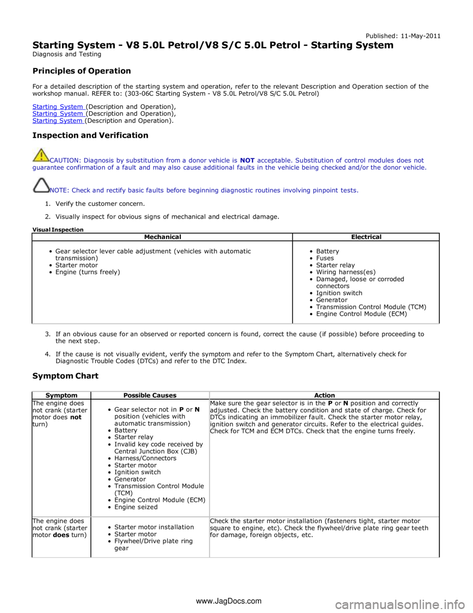
Visual Inspection
Mechanical Electrical
Gear selector lever cable adjustment (vehicles with automatic
transmission)
Starter motor
Engine (turns freely)
Battery
Fuses
Starter relay
Wiring harness(es)
Damaged, loose or corroded
connectors
Ignition switch
Generator
Transmission Control Module (TCM)
Engine Control Module (ECM)
3. If an obvious cause for an observed or reported concern is found, correct the cause (if possible) before proceeding to
the next step.
4. If the cause is not visually evident, verify the symptom and refer to the Symptom Chart, alternatively check for
Diagnostic Trouble Codes (DTCs) and refer to the DTC Index.
Symptom Chart
Symptom Possible Causes Action The engine does
not crank (starter
motor does not
turn)
Gear selector not in P or N
position (vehicles with
automatic transmission)
Battery
Starter relay
Invalid key code received by
Central Junction Box (CJB)
Harness/Connectors
Starter motor
Ignition switch
Generator
Transmission Control Module
(TCM)
Engine Control Module (ECM)
Engine seized Make sure the gear selector is in the P or N position and correctly
adjusted. Check the battery condition and state of charge. Check for
DTCs indicating an immobilizer fault. Check the starter motor relay,
ignition switch and generator circuits. Refer to the electrical guides.
Check for TCM and ECM DTCs. Check that the engine turns freely. The engine does
not crank (starter
motor does turn)
Starter motor installation
Starter motor
Flywheel/Drive plate ring
gear Check the starter motor installation (fasteners tight, starter motor
square to engine, etc). Check the flywheel/drive plate ring gear teeth
for damage, foreign objects, etc. www.JagDocs.com
Page 1265 of 3039
Starting System - V8 5.0L Petrol/V8 S/C 5.0L Petrol - Starting
System Vehicles With: Smart Key
Diagnosis and Testing
Principles of Operation Published: 06-Apr-2013
For a detailed description of the starting system, refer to the relevant Description and Operation section in the workshop
manual.
Inspection and Verification
1. Verify the customer concern.
2. Visually inspect for obvious signs of mechanical or electrical damage.
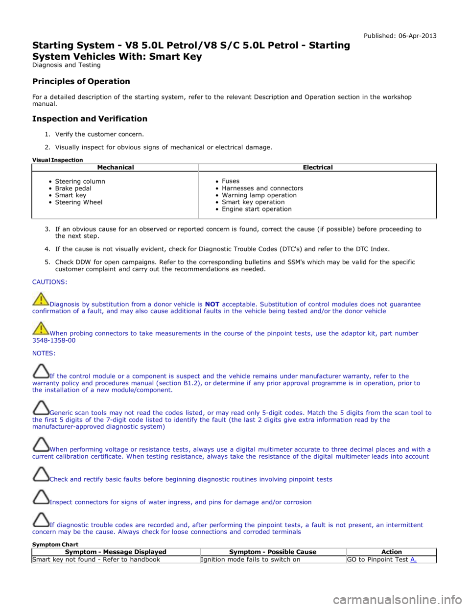
Visual Inspection
Mechanical Electrical
Steering column
Brake pedal
Smart key
Steering Wheel
Fuses
Harnesses and connectors
Warning lamp operation
Smart key operation
Engine start operation
3. If an obvious cause for an observed or reported concern is found, correct the cause (if possible) before proceeding to
the next step.
4. If the cause is not visually evident, check for Diagnostic Trouble Codes (DTC's) and refer to the DTC Index.
5. Check DDW for open campaigns. Refer to the corresponding bulletins and SSM's which may be valid for the specific
customer complaint and carry out the recommendations as needed.
CAUTIONS:
Diagnosis by substitution from a donor vehicle is NOT acceptable. Substitution of control modules does not guarantee
confirmation of a fault, and may also cause additional faults in the vehicle being tested and/or the donor vehicle
When probing connectors to take measurements in the course of the pinpoint tests, use the adaptor kit, part number
3548-1358-00
NOTES:
If the control module or a component is suspect and the vehicle remains under manufacturer warranty, refer to the
warranty policy and procedures manual (section B1.2), or determine if any prior approval programme is in operation, prior to
the installation of a new module/component.
Generic scan tools may not read the codes listed, or may read only 5-digit codes. Match the 5 digits from the scan tool to
the first 5 digits of the 7-digit code listed to identify the fault (the last 2 digits give extra information read by the
manufacturer-approved diagnostic system)
When performing voltage or resistance tests, always use a digital multimeter accurate to three decimal places and with a
current calibration certificate. When testing resistance, always take the resistance of the digital multimeter leads into account
Check and rectify basic faults before beginning diagnostic routines involving pinpoint tests
Inspect connectors for signs of water ingress, and pins for damage and/or corrosion
If diagnostic trouble codes are recorded and, after performing the pinpoint tests, a fault is not present, an intermittent
concern may be the cause. Always check for loose connections and corroded terminals
Symptom Chart
Symptom - Message Displayed Symptom - Possible Cause Action Smart key not found - Refer to handbook Ignition mode fails to switch on GO to Pinpoint Test A.
Page 1266 of 3039
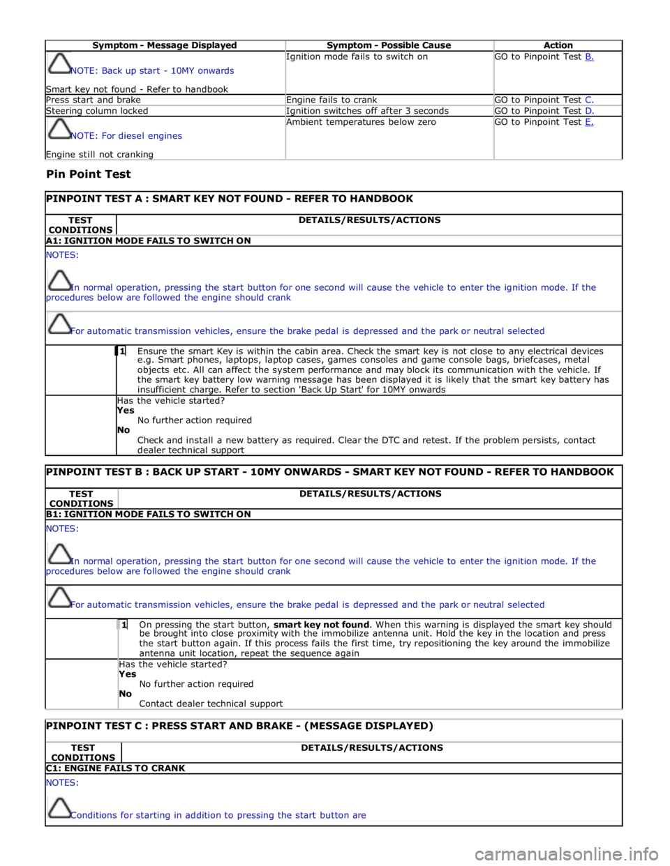
Symptom - Message Displayed Symptom - Possible Cause Action NOTE: Back up start - 10MY onwards
Smart key not found - Refer to handbook Ignition mode fails to switch on GO to Pinpoint Test B. Press start and brake Engine fails to crank GO to Pinpoint Test C. Steering column locked Ignition switches off after 3 seconds GO to Pinpoint Test D. NOTE: For diesel engines Engine still not cranking Ambient temperatures below zero GO to Pinpoint Test E.
Pin Point Test
PINPOINT TEST A : SMART KEY NOT FOUND - REFER TO HANDBOOK TEST
CONDITIONS DETAILS/RESULTS/ACTIONS A1: IGNITION MODE FAILS TO SWITCH ON NOTES:
In normal operation, pressing the start button for one second will cause the vehicle to enter the ignition mode. If the
procedures below are followed the engine should crank
For automatic transmission vehicles, ensure the brake pedal is depressed and the park or neutral selected 1 Ensure the smart Key is within the cabin area. Check the smart key is not close to any electrical devices e.g. Smart phones, laptops, laptop cases, games consoles and game console bags, briefcases, metal
objects etc. All can affect the system performance and may block its communication with the vehicle. If
the smart key battery low warning message has been displayed it is likely that the smart key battery has
insufficient charge. Refer to section 'Back Up Start' for 10MY onwards Has the vehicle started? Yes
No further action required
No
Check and install a new battery as required. Clear the DTC and retest. If the problem persists, contact
dealer technical support
PINPOINT TEST B : BACK UP START - 10MY ONWARDS - SMART KEY NOT FOUND - REFER TO HANDBOOK TEST
CONDITIONS DETAILS/RESULTS/ACTIONS B1: IGNITION MODE FAILS TO SWITCH ON NOTES:
In normal operation, pressing the start button for one second will cause the vehicle to enter the ignition mode. If the
procedures below are followed the engine should crank
For automatic transmission vehicles, ensure the brake pedal is depressed and the park or neutral selected 1 On pressing the start button, smart key not found. When this warning is displayed the smart key should be brought into close proximity with the immobilize antenna unit. Hold the key in the location and press
the start button again. If this process fails the first time, try repositioning the key around the immobilize
antenna unit location, repeat the sequence again Has the vehicle started? Yes
No further action required
No
Contact dealer technical support
PINPOINT TEST C : PRESS START AND BRAKE - (MESSAGE DISPLAYED) TEST
CONDITIONS DETAILS/RESULTS/ACTIONS C1: ENGINE FAILS TO CRANK NOTES:
Conditions for starting in addition to pressing the start button are
Page 1267 of 3039
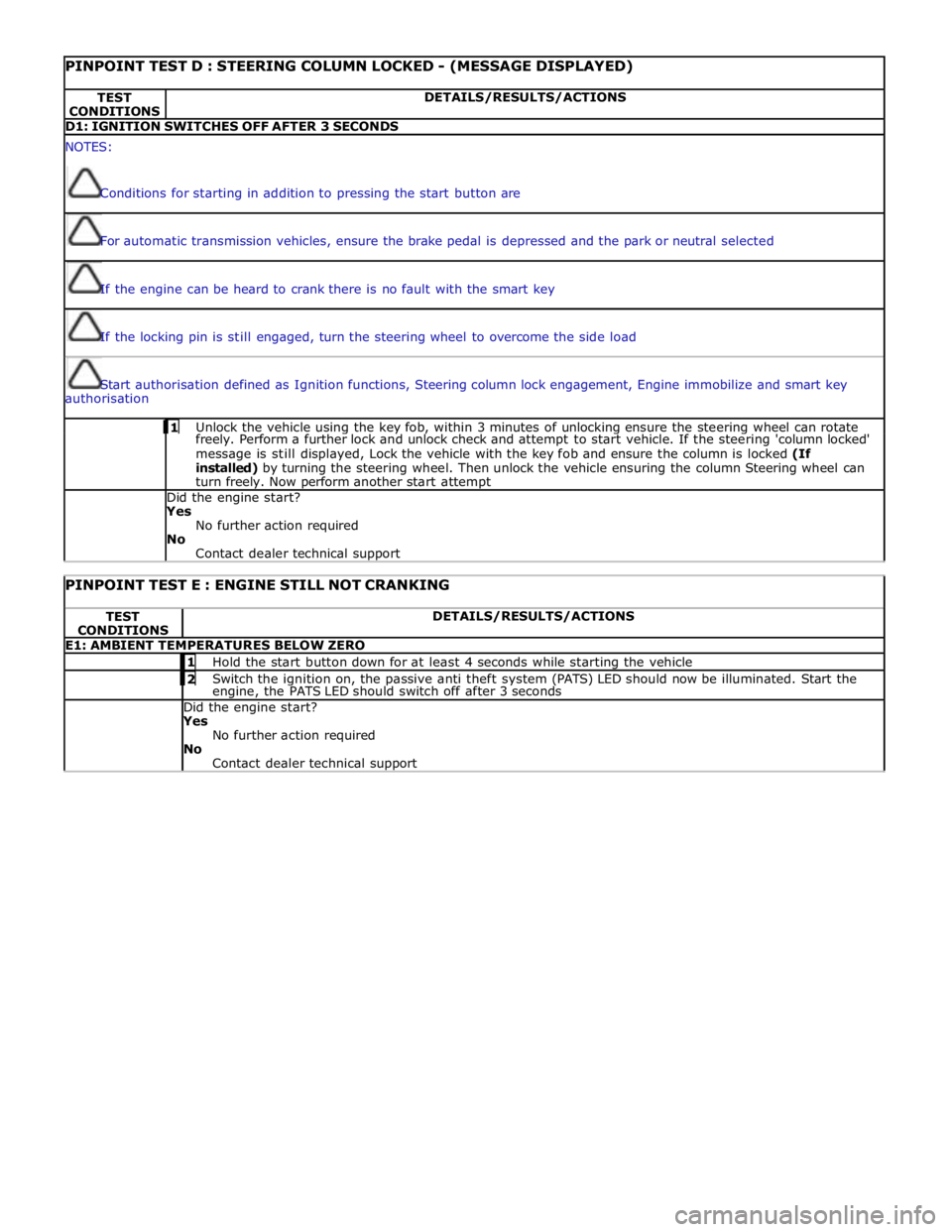
PINPOINT TEST D : STEERING COLUMN LOCKED - (MESSAGE DISPLAYED) TEST
CONDITIONS DETAILS/RESULTS/ACTIONS D1: IGNITION SWITCHES OFF AFTER 3 SECONDS NOTES:
Conditions for starting in addition to pressing the start button are
For automatic transmission vehicles, ensure the brake pedal is depressed and the park or neutral selected
If the engine can be heard to crank there is no fault with the smart key
If the locking pin is still engaged, turn the steering wheel to overcome the side load
Start authorisation defined as Ignition functions, Steering column lock engagement, Engine immobilize and smart key
authorisation 1 Unlock the vehicle using the key fob, within 3 minutes of unlocking ensure the steering wheel can rotate freely. Perform a further lock and unlock check and attempt to start vehicle. If the steering 'column locked'
message is still displayed, Lock the vehicle with the key fob and ensure the column is locked (If
installed) by turning the steering wheel. Then unlock the vehicle ensuring the column Steering wheel can
turn freely. Now perform another start attempt Did the engine start?
Yes
No further action required
No
Contact dealer technical support
PINPOINT TEST E : ENGINE STILL NOT CRANKING TEST
CONDITIONS DETAILS/RESULTS/ACTIONS E1: AMBIENT TEMPERATURES BELOW ZERO 1 Hold the start button down for at least 4 seconds while starting the vehicle 2 Switch the ignition on, the passive anti theft system (PATS) LED should now be illuminated. Start the engine, the PATS LED should switch off after 3 seconds Did the engine start? Yes
No further action required
No
Contact dealer technical support
Page 1270 of 3039

Firing order 1:2:7:3:4:5:6:8 Spark plug type - Vehicles with supercharger ILKAR6C-10 Spark plug type - Vehicles without supercharger ILKAR6C-10
Description Nm lb-ft lb-in Spark plugs 20 15 - Ignition coil-on-plug retaining bolts 7 5 -