Page 897 of 3039
17.
18.
Press the cruise control cancel button twice within 2
seconds.
The message center display will revert to the normal
display in the trip computer.
Scroll through the trip menu to access the engine oil
level display.
Check that the oil level display shows an oil level
reading.
Only after having started and run the engine for 10
minutes (as indicated in Step 14), switch off the
engine, then stabilizing for 10 minutes, take a
reading from the oil level display and, if necessary
top up with engine oil.
19. NOTE: If instructed to follow Steps 15-19 in a previous step, return
to Step 14 and continue the procedure.
Turn the ignition off.
20. Allow 10 minutes for the engine oil level to stabilize if there has been
additional oil top up.
Page 898 of 3039
21.
NOTE: The following steps are to update the average
oil level value.
Turn the ignition on.
Press and hold the cruise control cancel button for
more than 2 seconds.
22.
The message center display will revert to the normal display in
the trip computer.
23. Turn the ignition off.
24. Turn the ignition on.
25.
Scroll through the trip menu to access the engine oil
level display.
Make sure that the average oil level value has now
been updated.
26. Refer to: Air Deflector (501-02 Front End Body Panels, Removal and Installation).
Page 1081 of 3039
Check for leaks.
14. CAUTIONS:
Make sure that the selector lever and the gearshift mechanism are
in the park (P) position.
Make sure that the hood is open.
Turn the ignition on.
15.
Scroll through the trip menu to access the engine oil
level display. www.JagDocs.com
Page 1082 of 3039
16.
17.
Press the cruise control cancel button twice within 2
seconds.
The message center display will revert to the normal
display in the trip computer.
Scroll through the trip menu to access the engine oil
level display.
Check that the oil level display shows an oil level
reading.
Only after having started and run the engine for 10
minutes (as indicated in Step 13), switch off the
engine, then stabilizing for 10 minutes, take a
reading from the oil level display and, if necessary
top up with engine oil.
18. NOTE: If instructed to follow Steps 14-18 in a previous step, return
to Step 13 and continue the procedure.
Turn the ignition off.
19. Allow 10 minutes for the engine oil level to stabilize if there has been
additional oil top up.
Page 1083 of 3039
20.
NOTE: The following steps are to update the average
oil level value.
Turn the ignition on.
Press and hold the cruise control cancel button for
more than 2 seconds.
21.
The message center display will revert to the normal display in
the trip computer.
22. Turn the ignition off.
23. Turn the ignition on.
24.
Scroll through the trip menu to access the engine oil
level display.
Make sure that the average oil level value has now
been updated.
25. Refer to: Air Deflector (501-02 Front End Body Panels, Removal and Installation).
Page 1114 of 3039

14 Radiator 15 Auxiliary radiator 16 Connection with supercharger cooling system
System Operation
When the engine is running, the coolant is circulated around the engine cooling system by the coolant pump. From the coolant
pump, coolant flows through the cylinder heads and the engine oil cooler into the cylinder block and the heater manifold.
In the cylinder block, the coolant flows forwards to the outlet tube. When the coolant is cold, the thermostat is closed and the
coolant flows direct from the outlet tube back to the coolant pump. Once the coolant reaches operating temperature the
thermostat begins to open, to control system temperature, and coolant flows from the outlet tube to the coolant pump via the
radiator and, on SC (supercharger) vehicles, the auxiliary radiator. When the thermostat is open, the coolant flow through the
radiator(s) also generates a coolant flow through the transmission fluid cooler.
From the heater manifold the coolant flows through the electronic throttle and the heater core, in parallel circuits that are
unaffected by the position of the thermostat. From the electronic throttle, the coolant merges with bleed coolant from the
coolant pump and the outlet tube and flows to the expansion tank. From the heater core, the coolant flows back to the inlet of
the coolant pump.
Expansion and contraction of the coolant is accommodated by an air space in the expansion tank and the compliance of the
flexible hoses.
If the coolant level in the expansion tank decreases below a predetermined value, the level sensor connects a ground to the
instrument cluster, which activates the appropriate warning. For additional information, refer to 413-01 Instrument Cluster.
The cooling fan is operated by a fan control module integrated into the cooling fan motor. The fan control module regulates the
voltage, and thus speed, of the cooling fan motor in response to a PWM (pulse width modulation) signal from the ECM (engine
control module).
The cooling fan receives a battery feed and an ignition feed from the EJB (engine junction box). The ignition feed is supplied
from the main relay in the EJB, which is controlled by the ECM.
The ECM calculates the required fan speed from the engine temperature, A/C (air conditioning) system pressure and transmission fluid temperature. Under hot operating conditions, the fan may continue to operate for 4 minutes after the engine
has been switched off.
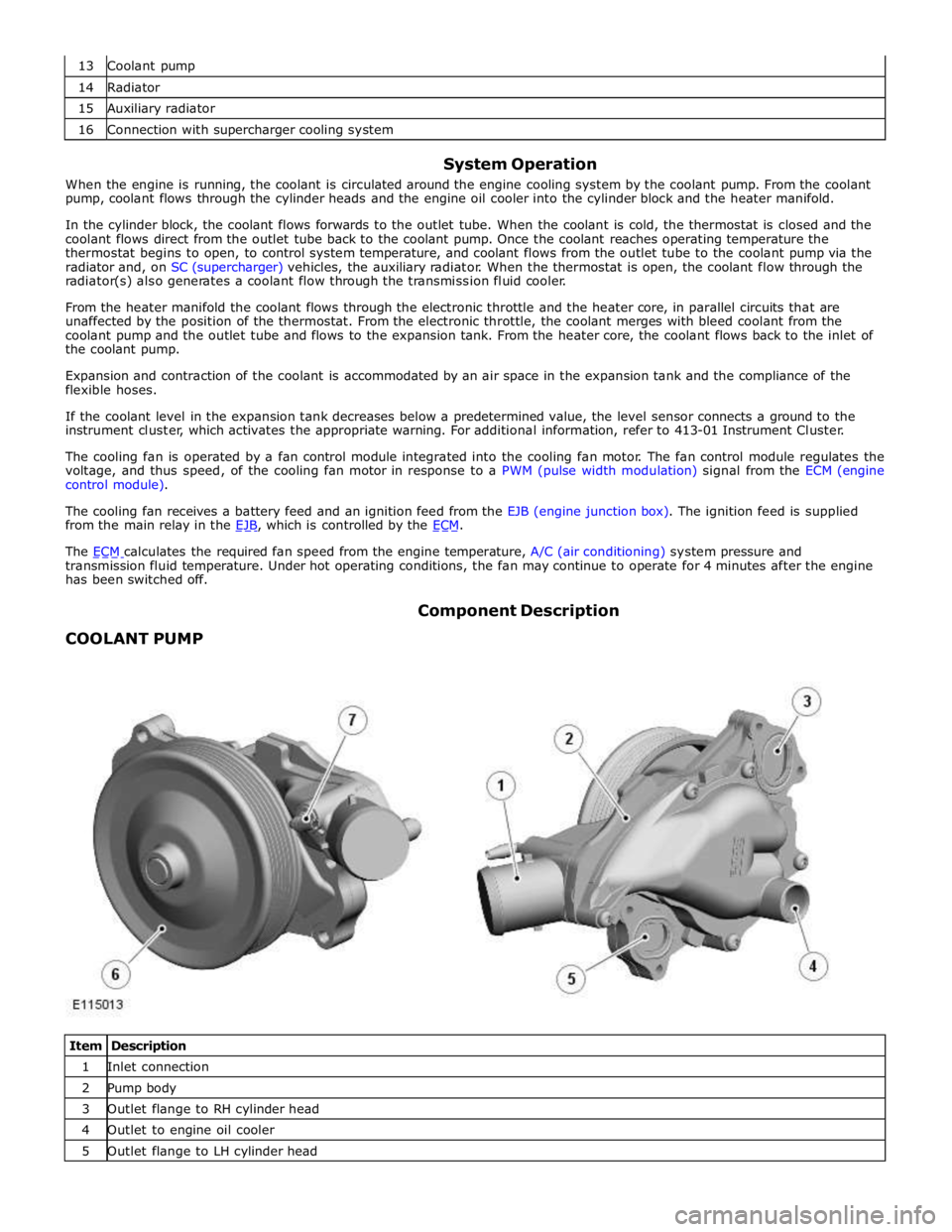
COOLANT PUMP Component Description
Item Description 1 Inlet connection 2 Pump body 3 Outlet flange to RH cylinder head 4 Outlet to engine oil cooler 5 Outlet flange to LH cylinder head
Page 1170 of 3039
1 RH (right hand) charge air cooler 2 Engine 3 LH (left hand) charge air cooler 4 Expansion hose connection (with engine cooling system) 5 Charge air radiator 6 Charge air coolant pump
System Operation
Electrical power for the charge air coolant pump is supplied from the intercooler water pump relay in the power distribution box.
When the intercooler water pump relay is energized, it connects power from the battery, via the BJB (battery junction box)
and CJB (central junction box), to the charge air coolant pump. Operation of the intercooler water pump relay is controlled by
the ECM (engine control module). The intercooler water pump relay is energized continuously while the ignition is in power
mode 6.
When the charge air coolant pump is running, coolant flows from the pump outlet through the charge air coolers, the charge air
radiator and back to the pump inlet. Supercharger Cooling Flow Diagram
Page 1177 of 3039

Fuel Charging and Controls - V8 S/C 5.0L Petrol -
WARNINGS: Published: 11-May-2011
Do not smoke or carry lighted tobacco or open flame of any type when working on or near any fuel related components.
Highly flammable vapors are always present and may ignite. Failure to follow these instructions may result in personal injury.
Before any work is carried out on the fuel system, ground the vehicle to earth and maintain the ground connection until
the work is complete.
CAUTION: Before disconnecting or removing components, make sure the area around the joint faces and connections are
clean. Plug open connections to prevent contamination.
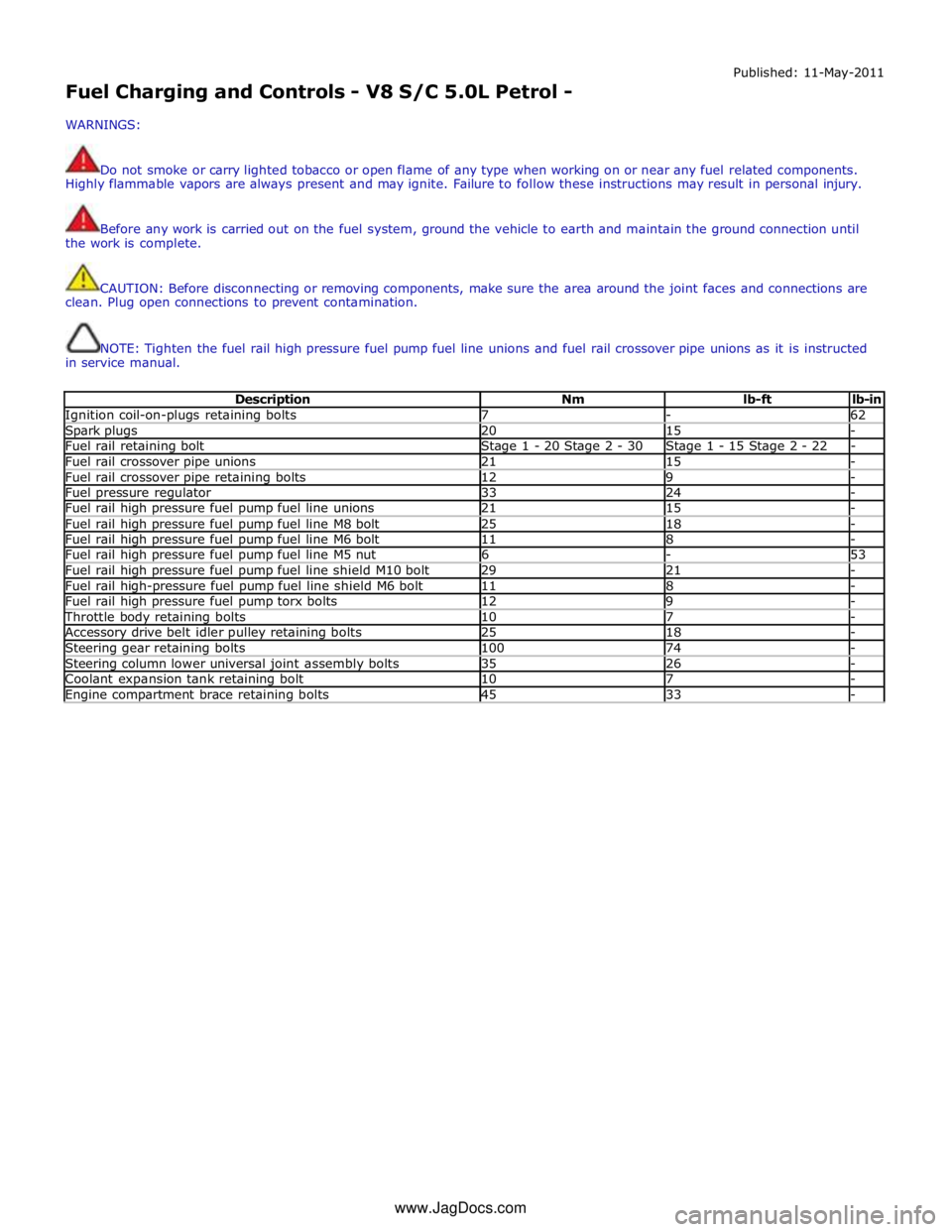
NOTE: Tighten the fuel rail high pressure fuel pump fuel line unions and fuel rail crossover pipe unions as it is instructed
in service manual.
Description Nm lb-ft lb-in Ignition coil-on-plugs retaining bolts 7 - 62 Spark plugs 20 15 - Fuel rail retaining bolt Stage 1 - 20 Stage 2 - 30 Stage 1 - 15 Stage 2 - 22 - Fuel rail crossover pipe unions 21 15 - Fuel rail crossover pipe retaining bolts 12 9 - Fuel pressure regulator 33 24 - Fuel rail high pressure fuel pump fuel line unions 21 15 - Fuel rail high pressure fuel pump fuel line M8 bolt 25 18 - Fuel rail high pressure fuel pump fuel line M6 bolt 11 8 - Fuel rail high pressure fuel pump fuel line M5 nut 6 - 53 Fuel rail high pressure fuel pump fuel line shield M10 bolt 29 21 - Fuel rail high-pressure fuel pump fuel line shield M6 bolt 11 8 - Fuel rail high pressure fuel pump torx bolts 12 9 - Throttle body retaining bolts 10 7 - Accessory drive belt idler pulley retaining bolts 25 18 - Steering gear retaining bolts 100 74 - Steering column lower universal joint assembly bolts 35 26 - Coolant expansion tank retaining bolt 10 7 - Engine compartment brace retaining bolts 45 33 - www.JagDocs.com