2010 JAGUAR XFR ignition
[x] Cancel search: ignitionPage 1577 of 3039

Fuel System - General Information - Quick Release Coupling
General Procedures
Disconnect Published: 11-May-2011
1. WARNINGS:
Place the vehicle in a quarantined area and arrange "No
Smoking/Petrol Fumes" signs about the vehicle.
Before any work is carried out on the fuel system, ground the
vehicle to earth and maintain the ground connection until the work is
complete.
Do not smoke or carry lighted tobacco or open flame of any type
when working on or near any fuel related components. Highly flammable
vapors are always present and may ignite. Failure to follow these
instructions may result in personal injury.
The fuel system remains pressurized for a long time after the
ignition is switched off. The fuel pressure must be relieved before
attempting any repairs. Failure to follow these instructions may result in
personal injury.
After carrying out repairs, the fuel system must be checked visually
for leaks. Failure to follow these instructions may result in personal
injury.
This procedure involves fuel handling. Be prepared for fuel spillage
at all times and always observe fuel handling precautions. Failure to
follow these instructions may result in personal injury.
If taken internally do not induce vomiting, seek immediate medical
attention. Failure to follow these instructions may result in personal
injury.
If fuel contacts the eyes, flush the eyes with cold water or
eyewash solution and seek medical attention.
Wash hands thoroughly after handling, as prolonged contact may
cause irritation. Should irritation develop, seek medical attention.
Relieve the fuel system pressure. For additional information, refer to the
procedure in this section: Pressure Relief.
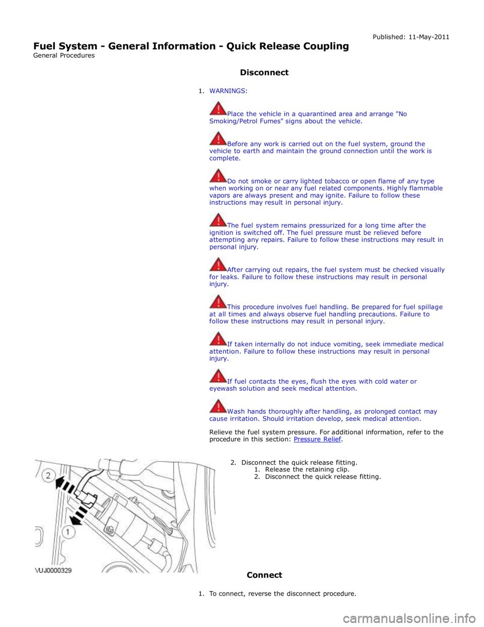
2. Disconnect the quick release fitting.
1. Release the retaining clip.
2. Disconnect the quick release fitting.
Connect
1. To connect, reverse the disconnect procedure.
Page 1578 of 3039

Published: 11-May-2011
Fuel System - General Information - Quick Release Coupling - Push Connect
General Procedures
Disconnect
1. WARNINGS:
Place the vehicle in a quarantined area and arrange "No
Smoking/Petrol Fumes" signs about the vehicle.
Before any work is carried out on the fuel system, ground the
vehicle to earth and maintain the ground connection until the work is
complete.
Do not smoke or carry lighted tobacco or open flame of any type
when working on or near any fuel related components. Highly flammable
vapors are always present and may ignite. Failure to follow these
instructions may result in personal injury.
The fuel system remains pressurized for a long time after the
ignition is switched off. The fuel pressure must be relieved before
attempting any repairs. Failure to follow these instructions may result in
personal injury.
After carrying out repairs, the fuel system must be checked visually
for leaks. Failure to follow these instructions may result in personal
injury.
This procedure involves fuel handling. Be prepared for fuel spillage
at all times and always observe fuel handling precautions. Failure to
follow these instructions may result in personal injury.
If taken internally do not induce vomiting, seek immediate medical
attention. Failure to follow these instructions may result in personal
injury.
If fuel contacts the eyes, flush the eyes with cold water or
eyewash solution and seek medical attention.
Wash hands thoroughly after handling, as prolonged contact may
cause irritation. Should irritation develop, seek medical attention.
Relieve the fuel system pressure. For additional information, refer to the
procedure in this section:
For additional information, refer to: Fuel System Pressure Release
(310-00 Fuel System - General Information, General Procedures).
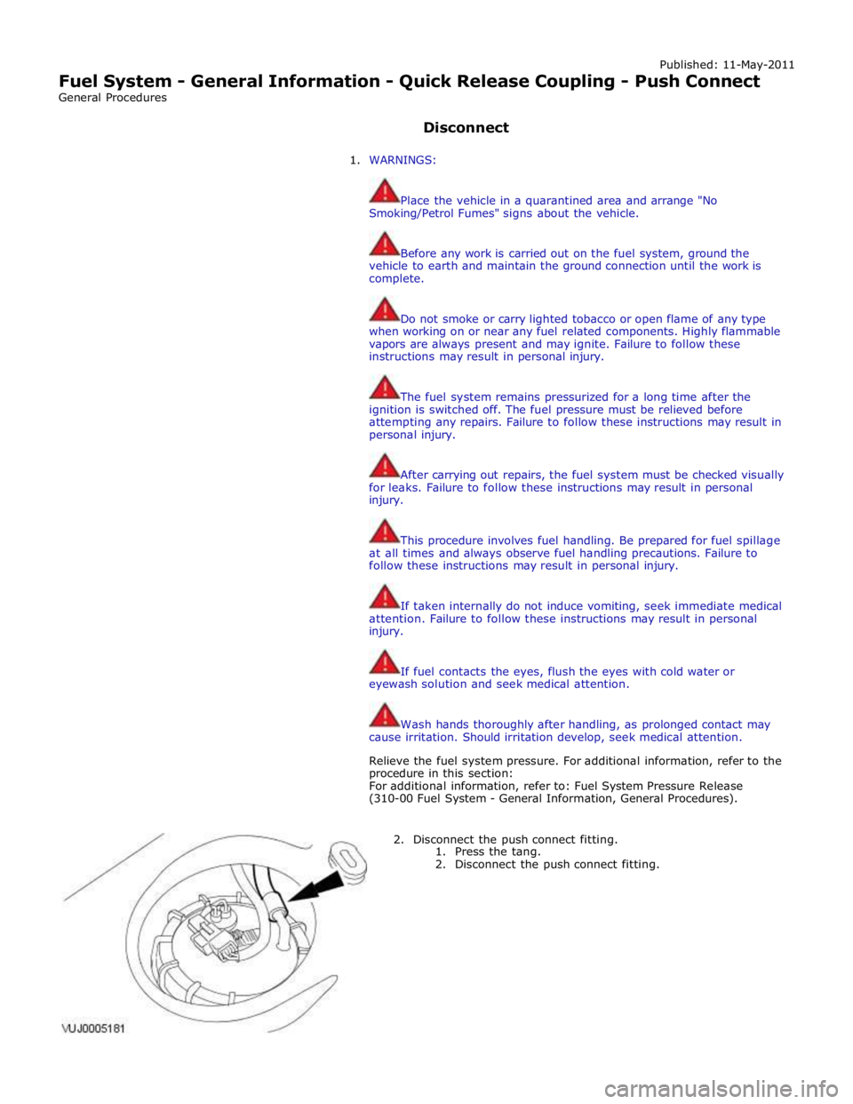
2. Disconnect the push connect fitting.
1. Press the tang.
2. Disconnect the push connect fitting.
Page 1596 of 3039

Visual Inspection
Mechanical Electrical
Low/contaminated fuel
Fuel supply/return line(s)
Fuel tank and filler pipe
Fuel leak(s)
Fuel filler cap
Fuel filter
Push connect fittings
Fuel pump
Fuses
Links
Relays
Fuel Pump Driver Module (FPDM)
Fuel pump module
Sensor(s)
Engine control module (ECM)
Rear Junction Box (RJB)
Restraints Control Module (RCM)
3. If an obvious cause for an observed or reported concern is found, correct the cause (if possible) before proceeding to
the next step
4. If the cause is not visually evident, verify the symptom and refer to the Symptom Chart, alternatively check for
Diagnostic Trouble Codes (DTCs) and proceed to the DTC Index
Symptom Chart
Symptom Possible Causes Action Engine cranks, but does not
fire
Engine breather system
disconnected/restricted
Ignition system
Fuel system
Electronic engine control
Ensure the engine breather system is free from
restriction and is correctly installed
Check for ignition system, fuel system and electronic
engine control DTCs and refer to the relevant DTC
Index Engine cranks and fires, but
will not start
Evaporative emissions purge
valve
Fuel pump
Spark plugs
HT short to ground (tracking)
check rubber boots for
cracks/damage
Ignition system
Check for evaporative emissions, fuel system and
ignition system related DTCs and refer to the
relevant DTC Index Difficult cold start
Engine coolant level/anti-
freeze content
Battery
Electronic engine controls
Fuel pump
Purge valve
Check the engine coolant level and condition
Ensure the battery is in a fully charged and
serviceable condition
Check for electronic engine controls, engine
emissions, fuel system and evaporative emissions
system related DTCs and refer to the relevant DTC
Index Difficult hot start
Injector leak
Electronic engine control
Purge valve
Fuel pump
Ignition system
Check for injector leak, install new injector as
required
Check for electronic engine controls, evaporative
emissions, fuel system, ignition system and engine
emission system related DTCs and refer to the
relevant DTC Index Difficult to start after hot
soak (vehicle standing,
engine off, after engine has
reached operating
temperature)
Injector leak
Electronic engine control
Purge valve
Fuel pump
Ignition system
Check for injector leak, install new injector as
required
Check for electronic engine controls, evaporative
emissions, fuel system, ignition system and engine
emission system related DTCs and refer to the
relevant DTC Index Engine stalls soon after start
Breather system
disconnected/restricted
ECM relay
Electronic engine control
Ignition system
Air intake system restricted
Air leakage
Fuel lines
Ensure the engine breather system is free from
restriction and is correctly installed
Check for electronic engine control, ignition system
and fuel system related DTCs and refer to the
relevant DTC Index
Check for blockage in air filter element and air
intake system
Check for air leakage in air intake system Engine hesitates/poor
acceleration
Fuel pressure, fuel pump,
fuel lines
Injector leak
Air leakage
Check for fuel system related DTCs and refer to the
relevant DTC Index
Check for injector leak, install new injector as
required www.JagDocs.com
Page 1597 of 3039

Symptom Possible Causes Action Electronic engine control
Throttle motor
Restricted accelerator pedal
travel (carpet, etc)
Ignition system
Transmission malfunction Check for air leakage in air intake system
Ensure accelerator pedal is free from restriction
Check for electronic engine controls, ignition, engine
emission system and transmission related DTCs and
refer to the relevant DTC Index Engine backfires
Fuel pump/lines
Air leakage
Electronic engine controls
Ignition system
Sticking variable camshaft
timing (VCT) hub
Check for fuel system failures
Check for air leakage in intake air system
Check for electronic engine controls, ignition system
and VCT system related DTCs and refer to the
relevant DTC Index Engine surges
Fuel pump/lines
Electronic engine controls
Throttle motor
Ignition system
Check for fuel system failures
Check for electronic engine controls, throttle system
and ignition system related DTCs and refer to the
relevant DTC Index Engine detonates/knocks
Fuel pump/lines
Air leakage
Electronic engine controls
Sticking VCT hub
Check for fuel system failures
Check for air leakage in intake air system
Check for electronic engine controls and VCT system
related DTCs and refer to the relevant DTC Index No throttle response
Electronic engine controls
Throttle motor
Check for electronic engine controls and throttle
system related DTCs and refer to the relevant DTC
Index Poor throttle response
Breather system
disconnected/restricted
Electronic engine controls
Transmission malfunction
Traction control event
Air leakage
Ensure the engine breather system is free from
restriction and is correctly installed
Check for electronic engine controls, transmission
and traction control related DTCs and refer to the
related DTC Index
Check for air leakage in intake air system Fuel gauge reading empty
with fuel in the fuel tank
Active fuel level sensor
circuit open circuit
Passive fuel level sensor
circuit open circuit
Instrument cluster internal
failure
Using the manufacturer approved diagnostic system,
perform the guided diagnostic routine - Fuel Level
Sensor Test Fuel gauge not reading empty
with no fuel in the fuel tank
Jet pump fault
Fuel crossover tube blocked
or leaking
Using the manufacturer approved diagnostic system,
check datalogger signals - Fuel Sender 2 (0x61B8) -
Fuel Sender 1 (0x61B7). Refer to the table below. If
the right sensor reads empty when the left sensor
reads more than empty, check that the jet pump is
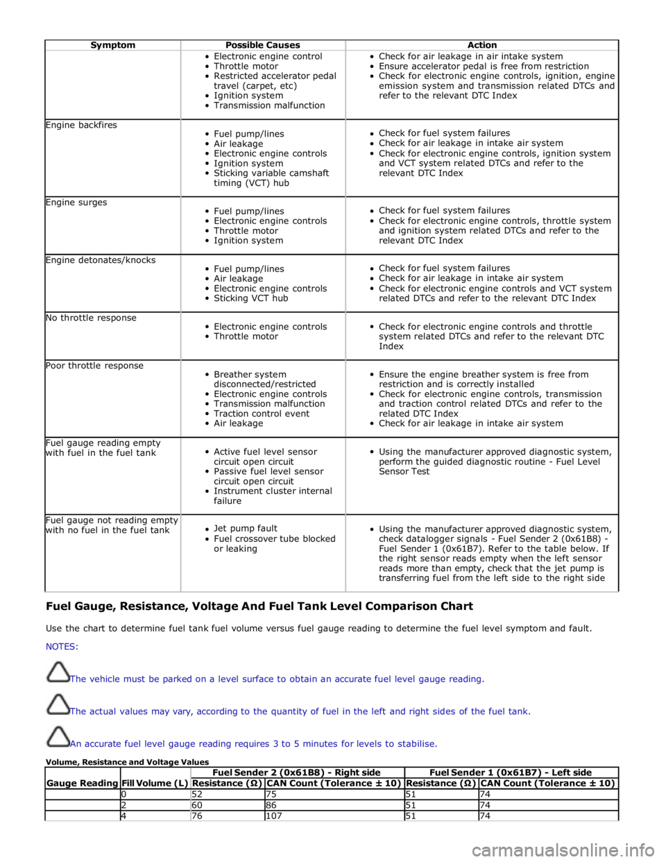
transferring fuel from the left side to the right side Fuel Gauge, Resistance, Voltage And Fuel Tank Level Comparison Chart
Use the chart to determine fuel tank fuel volume versus fuel gauge reading to determine the fuel level symptom and fault.
NOTES:
The vehicle must be parked on a level surface to obtain an accurate fuel level gauge reading.
The actual values may vary, according to the quantity of fuel in the left and right sides of the fuel tank.
An accurate fuel level gauge reading requires 3 to 5 minutes for levels to stabilise.
Volume, Resistance and Voltage Values
Gauge Reading
Fill Volume (L) Fuel Sender 2 (0x61B8) - Right side Fuel Sender 1 (0x61B7) - Left side Resistance (Ω) CAN Count (Tolerance ± 10) Resistance (Ω) CAN Count (Tolerance ± 10) 0 52 75 51 74 2 60 86 51 74 4 76 107 51 74
Page 1633 of 3039

DTC Description Possible Cause Action ECM fault
P210500 Throttle Actuator
Control System -
Forced Engine
Shutdown
Throttle MIL
request due to fuel
cut Carry out any pinpoint tests associated with this DTC using the
manufacturer approved diagnostic system P211800 Throttle Actuator
Control Motor Current
Range/Performance
Throttle motor
control circuit -
short to ground,
power, high
resistance Carry out any pinpoint tests associated with this DTC using the
manufacturer approved diagnostic system. Refer to the electrical
circuit diagrams and check throttle motor control circuit for short to
ground, power, high resistance P211900 Throttle Actuator
Control Throttle Body
Range/Performance
Throttle spring
faulty Carry out any pinpoint tests associated with this DTC using the
manufacturer approved diagnostic system. Suspect throttle body
faulty. Check and install a new throttle body as required, refer to
the new module/component installation note at top of DTC Index P212200 Throttle/Pedal
Position Sensor/Switch
D Circuit Low
APP sensor circuit 2
- low input Carry out any pinpoint tests associated with this DTC using the
manufacturer approved diagnostic system. Refer to the electrical
circuit diagrams and check APP sensor circuit 2 for short to ground, open circuit P212216 Throttle/Pedal
Position Sensor/Switch
D Circuit Low Input
Accelerator pedal
position (APP)
sensor circuit 1 -
short to ground,
power
Accelerator pedal
position (APP)
sensor failure Carry out any pinpoint tests associated with this DTC using the
manufacturer approved diagnostic system. Refer to electrical circuit
diagrams and check accelerator pedal position (APP) sensor circuit 1
for short to ground, power. Set ignition status to 'ON' engine 'OFF'
check and record 'Pedal value sensor 1' datalogger signal. With
pedal in idle position, value of signal should be approximately 0%,
if not suspect the pedal position sensor, check and install a new
sensor as required P212300 Throttle/Pedal
Position Sensor/Switch
D Circuit High
APP sensor circuit 2
- high input Carry out any pinpoint tests associated with this DTC using the
manufacturer approved diagnostic system. Refer to the electrical
circuit diagrams and check APP sensor circuit 2 for short to power P212317 Throttle/Pedal
Position Sensor/Switch
D Circuit High Input
Accelerator pedal
position (APP)
sensor circuit 1 -
short to power
Accelerator pedal
position (APP)
sensor failure Carry out any pinpoint tests associated with this DTC using the
manufacturer approved diagnostic system. Refer to electrical circuit
diagrams and check accelerator pedal position (APP) sensor circuit 1
for short to ground, power. Set ignition status to 'ON' engine 'OFF'
check and record 'Pedal value sensor 1' datalogger signal. With
pedal in fully depressed position, value of signal should be
approximately 99%, if not suspect the pedal position sensor, check
and install a new sensor as required P212716 Throttle/Pedal
Position Sensor/Switch
E Circuit Low Input
Accelerator pedal
position (APP)
sensor circuit 2 -
short to ground,
high resistance
Accelerator pedal
position (APP)
sensor failure Carry out any pinpoint tests associated with this DTC using the
manufacturer approved diagnostic system. Refer to electrical circuit
diagrams and check accelerator pedal position (APP) sensor circuit 2
for short to ground, power. Set ignition status to 'ON' engine 'OFF'
check and record 'Pedal value sensor 2' datalogger signal. With
pedal in idle position, value of signal should be approximately 0%,
if not suspect the pedal position sensor, check and install a new
sensor as required P212817 Throttle/Pedal
Position Sensor/Switch
E Circuit High Input
Accelerator pedal
position (APP)
sensor circuit 2 -
short to power
Accelerator pedal
position (APP)
sensor failure Carry out any pinpoint tests associated with this DTC using the
manufacturer approved diagnostic system. Refer to electrical circuit
diagrams and check accelerator pedal position (APP) sensor circuit 2
for short to ground, power. Set ignition status to 'ON' engine 'OFF'
check and record 'Pedal value sensor 2' datalogger signal. With
pedal in fully depressed position, value of signal should be
approximately 99%, if not suspect the pedal position sensor, check
and install a new sensor as required P213528 Throttle/Pedal
Position Sensor/Switch
A/B Voltage
Correlation
APP sensor circuit 1
and 2 range
performance -
sub-processor Carry out any pinpoint tests associated with this DTC using the
manufacturer approved diagnostic system. Refer to the electrical
circuit diagrams and check APP sensor circuits 1 and 2 for short to
ground, power and high resistance. Clear the DTCs and retest. If
the code remains, replace the APP sensor P213529 Throttle/Pedal
Position Sensor/Switch
A/B Voltage
Correlation
APP sensor -
excessive difference
between
raw values of circuit
1 and 2 -
sub-processor Carry out any pinpoint tests associated with this DTC using the
manufacturer approved diagnostic system. Refer to the electrical
circuit diagrams and check APP sensor circuits 1 and 2 for short,
open circuit
Page 1634 of 3039

DTC Description Possible Cause Action P213562 Throttle/Pedal
Position Sensor/Switch
A/B Voltage
Correlation
APP sensor circuit 1
and 2 range
performance -
sub-processor Carry out any pinpoint tests associated with this DTC using the
manufacturer approved diagnostic system. Refer to the electrical
circuit diagrams and check APP sensor circuits 1 and 2 for short to
ground, power and high resistance. Clear the DTCs and retest. If
the code remains, replace the APP sensor P213564 Throttle/Pedal
Position Sensor/Switch
A/B Voltage
Correlation
APP sensor circuit 1
and 2 range
performance Carry out any pinpoint tests associated with this DTC using the
manufacturer approved diagnostic system. Refer to the electrical
circuit diagrams and check APP sensor circuits 1 and 2 for short,
open circuit P213862 Throttle/Pedal
Position Sensor/Switch
D/E Voltage
Correlation
Pedal value
difference between
channel 1 and
channel 2 greater
than a threshold Carry out any pinpoint tests associated with this DTC using the
manufacturer approved diagnostic system. Refer to electrical circuit
diagrams and check accelerator pedal position (APP) sensor circuit 1
and 2 for short to ground, power. Set ignition status to 'ON' engine
'OFF' check and record 'Pedal value sensor 1' and 'Pedal value
sensor 2' datalogger signal. With pedal in fully depressed position,
value of signals should be approximately 99%, with pedal in idle
position, value of signals should be approximately 0%, if not
suspect the pedal position sensor, check and install a new sensor
as required P213864 Throttle/Pedal
Position Sensor/Switch
D/E Voltage
Correlation
Gradient on one
channel without
gradient on the
other Carry out any pinpoint tests associated with this DTC using the
manufacturer approved diagnostic system. Refer to electrical circuit
diagrams and check accelerator pedal position (APP) sensor circuit 1
and 2 for short to ground, power. Set ignition status to 'ON' engine
'OFF' check and record 'Pedal value sensor 1' and 'Pedal value
sensor 2' datalogger signal. With pedal in fully depressed position,
value of signals should be approximately 99%, with pedal in idle
position, value of signals should be approximately 0%, if not
suspect the pedal position sensor, check and install a new sensor
as required
Page 1642 of 3039

longitudinal axis of the vehicle. The radar operates at millimetric wavelengths (76 - 77 GHz) and transmits a frequency
modulated continuous wave signal at a relatively low power level (no high power pulses).
With the ignition ON, the adaptive speed control module is powered up but no radar transmissions are emitted until the
vehicle is in motion.
In follow mode a set speed is selected in the normal speed control manner and this speed is maintained until a slower vehicle
is encountered in the lane ahead. When the vehicle ahead comes within the effective range of the radar sensor, the system
identifies it as a target vehicle and an icon is illuminated on the instrument cluster to indicate that the system is in "follow
mode". When the distance between the two vehicles closes to a set time gap, the adaptive speed control system closes the
throttle and if necessary applies the brakes to maintain the set time gap. Follow mode is effectively a closed loop system. If
several vehicles are ahead, the closest vehicle is chosen as the target to follow. If the target vehicle moves out of radar range,
or if either vehicle changes lane or drops below the minimum operating speed, the system exits follow mode and the follow
mode icon is extinguished. The adaptive speed control system will only raise its speed to the originally set speed, it will not
accelerate past this speed to maintain a time gap.
Driver operation of the foot brake or control switches will immediately cancel adaptive speed control.
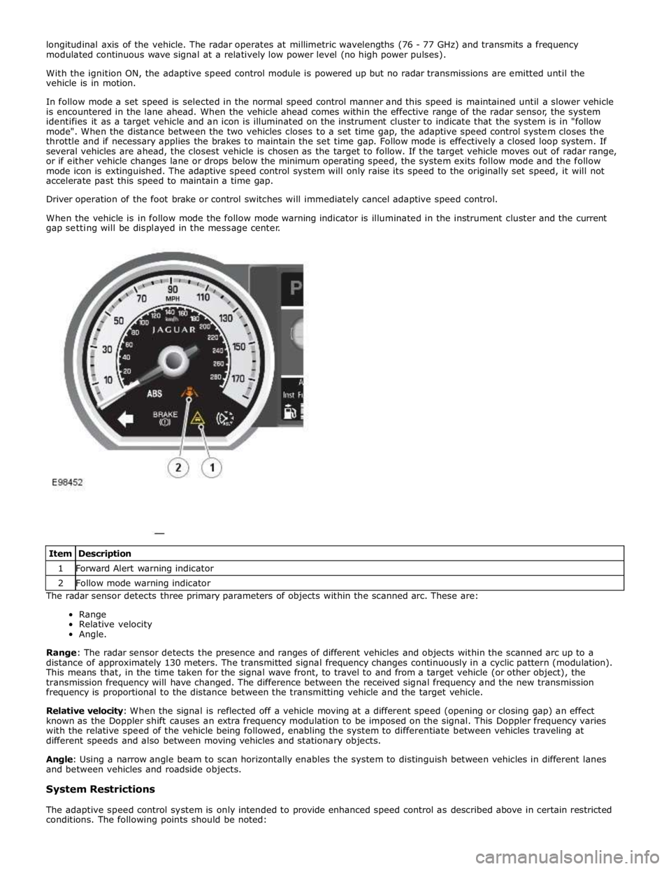
When the vehicle is in follow mode the follow mode warning indicator is illuminated in the instrument cluster and the current
gap setting will be displayed in the message center.
The radar sensor detects three primary parameters of objects within the scanned arc. These are:
Range
Relative velocity
Angle.
Range: The radar sensor detects the presence and ranges of different vehicles and objects within the scanned arc up to a
distance of approximately 130 meters. The transmitted signal frequency changes continuously in a cyclic pattern (modulation).
This means that, in the time taken for the signal wave front, to travel to and from a target vehicle (or other object), the
transmission frequency will have changed. The difference between the received signal frequency and the new transmission
frequency is proportional to the distance between the transmitting vehicle and the target vehicle.
Relative velocity: When the signal is reflected off a vehicle moving at a different speed (opening or closing gap) an effect
known as the Doppler shift causes an extra frequency modulation to be imposed on the signal. This Doppler frequency varies
with the relative speed of the vehicle being followed, enabling the system to differentiate between vehicles traveling at
different speeds and also between moving vehicles and stationary objects.
Angle: Using a narrow angle beam to scan horizontally enables the system to distinguish between vehicles in different lanes
and between vehicles and roadside objects.
System Restrictions
The adaptive speed control system is only intended to provide enhanced speed control as described above in certain restricted
conditions. The following points should be noted: Item Description 1 Forward Alert warning indicator 2 Follow mode warning indicator
Page 1681 of 3039

Published: 15-Nov-2013
Climate Control System - General Information - Air Conditioning (A/C)
Compressor Commissioning
General Procedures
Activation
CAUTION: Failure to follow this instruction may result in damage to the component.
1. Set the ignition to the on position, make sure the air conditioning (A/C)
is in the off position.
2. Start the engine and allow to run for a minimum of 5 minutes.
3. Set the heater controls to 22°C, with the fan speed set to 75%.
4. Switch on the A/C system.
5. Open all air vents in the dashboard.
6. Run the A/C system for a minimum of 5 minutes, while the engine is still
at idle speed.
7. Once this is achieved the compressor is stabilized, with the oil being
distributed evenly throughout the system.