2010 JAGUAR XFR ignition
[x] Cancel search: ignitionPage 1845 of 3039
3 RJB 4 Entertainment system control module 5 Touch Screen Display (TSD) 6 Parking aid camera
PARKING AID System Operation
Two levels of parking aid system can be fitted; a rear only system or a front and rear system.
The parking aid module receives and ignition power mode 6 supply from the RJB. The parking aid module is connected to the entertainment system control module by the medium speed CAN (controller area
network) bus and the Media Orientated System Transport (MOST). The entertainment system is used by the parking aid system
to provide the driver with an audible warning. If an obstacle is sensed by the rear parking aid sensors, the rear audio system
speakers will sound. If an obstacle is sensed by the front parking aid sensors (if fitted), the front audio system speakers will
sound.
The parking aid system operates using ultrasonic signals which are transmitted by the sensors. The reflected echo from this
output is received by the sensors and used by the parking aid module to calculate the distance from an object.
When the parking aid module activates the system, the switch LED (light emitting diode) is illuminated to indicate that the
system is operating. The parking aid module then processes signals received from the sensors to determine if there is an
object with the detection range of the sensors. A parking aid screen is automatically displayed in the Touch Screen Display. If
the vehicle has a parking aid camera fitted, the camera display is automatically displayed in the TSD in preference to the
parking aid alert display. To view the parking aid sensor display, a single touch of the TSD screen will remove the camera
image display and show the parking aid alert display.
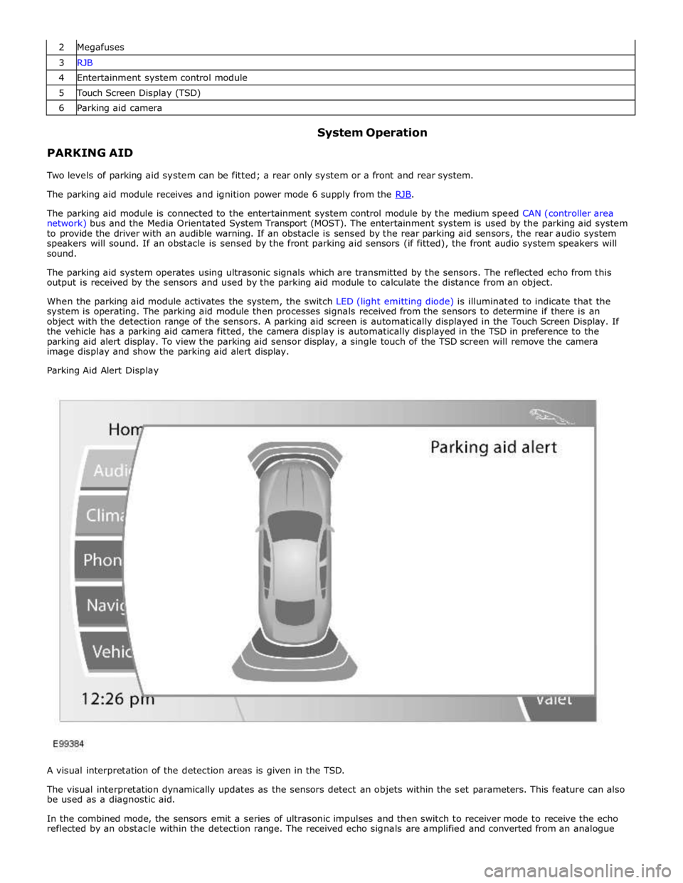
Parking Aid Alert Display
A visual interpretation of the detection areas is given in the TSD.
The visual interpretation dynamically updates as the sensors detect an objets within the set parameters. This feature can also
be used as a diagnostic aid.
In the combined mode, the sensors emit a series of ultrasonic impulses and then switch to receiver mode to receive the echo
reflected by an obstacle within the detection range. The received echo signals are amplified and converted from an analogue
Page 1846 of 3039
signal to a digital signal by the sensor. The digital signal is passed to the parking aid module and compared with
pre-programmed data stored in an EEPROM (electrically erasable programmable read only memory) within the module. The
module receives this data via the signal line from the sensor and calculates the distance from the object using the elapsed
time between the transmitted and received impulse. The duration of the impulse duration is determined by the module, with
the sensor controlling the frequency of the impulse output.
In receiver mode, the sensor receives impulses that were emitted by adjacent sensors. The module uses this information to
precisely determine the position and distance of the object.
If no objects are detected there are no further warning tones. If an object is detected, repeated audible tones are emitted
from either the front or rear audio speakers as appropriate. The time delay between the tones decreases as the distance
between the object and the vehicle decreases, until at approximately 300 mm (12 inches), the audible tone becomes
continuous.
After the initial detection of an object, if there is no decrease in the distance between an object and the central sensors, the
time delay between the audible warnings remains constant. If an object is detected by one of the corner sensors only, the
audible warnings stop after approximately 5 seconds if there is no change in the distance between an object and the corner
sensor.
When approaching several objects within detection range, the control module recognises the distance from the vehicle to the
nearest object.
The PDC module will prioritise the objects detected, the nearest object detected will take priority and the corresponding audio
outputs will be emitted. For example if 2 objects are detected (one front one rear) the nearest detected object will take
priority and relevant audible tone will be heard.
If two objects are detected at equal distance (one front one rear) the audible tones will alternate between the front and rear
speakers.
If reverse (R) is the first gear selected after the ignition is switched on, both the front (if fitted) and rear parking aid sensors
will become operational. If a forward drive gear is subsequently selected, the front and rear parking aid sensors will remain
operational until vehicle speed increases above 16 km/h (10 mph), park (P) is selected or the PDC control switch is pressed.
If drive (D) is the first gear selected after the ignition is switched on the parking aid system will have to be activated by
pressing the PDC control switch.
NOTE: The PDC system can not be activated whilst the vehicle is in park (P).
The volume output of the parking aid audible tones can be adjusted by selecting the 'Vehicle Settings' menu and selecting
'Parking' from the menu on the TSD. The volume can be adjusted using the + or - selections on the TSD.
The system can detect when a trailer is connected to the vehicle by a message output on the medium speed CAN bus from the trailer module. When the parking aid module detects that a trailer is connected to the vehicle, the rear sensors are disabled to
prevent constant warnings due to the close proximity of the trailer.
NOTE: The ignition needs to be cycled once the trailer has been disconnected to activate the rear parking aid system.
Page 1847 of 3039
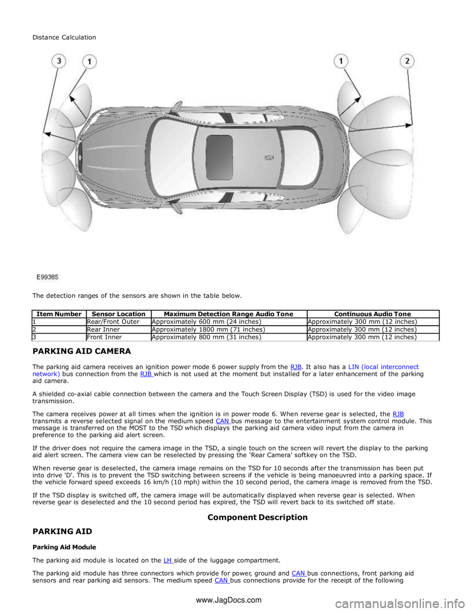
1 Rear/Front Outer Approximately 600 mm (24 inches) Approximately 300 mm (12 inches) 2 Rear Inner Approximately 1800 mm (71 inches) Approximately 300 mm (12 inches) 3 Front Inner Approximately 800 mm (31 inches) Approximately 300 mm (12 inches) PARKING AID CAMERA
The parking aid camera receives an ignition power mode 6 power supply from the RJB. It also has a LIN (local interconnect network) bus connection from the RJB which is not used at the moment but installed for a later enhancement of the parking aid camera.
A shielded co-axial cable connection between the camera and the Touch Screen Display (TSD) is used for the video image
transmission.
The camera receives power at all times when the ignition is in power mode 6. When reverse gear is selected, the RJB transmits a reverse selected signal on the medium speed CAN bus message to the entertainment system control module. This message is transferred on the MOST to the TSD which displays the parking aid camera video input from the camera in
preference to the parking aid alert screen.
If the driver does not require the camera image in the TSD, a single touch on the screen will revert the display to the parking
aid alert screen. The camera view can be reselected by pressing the 'Rear Camera' softkey on the TSD.
When reverse gear is deselected, the camera image remains on the TSD for 10 seconds after the transmission has been put
into drive 'D'. This is to prevent the TSD switching between screens if the vehicle is being manoeuvred into a parking space. If
the vehicle forward speed exceeds 16 km/h (10 mph) within the 10 second period, the camera image is removed from the TSD.
If the TSD display is switched off, the camera image will be automatically displayed when reverse gear is selected. When
reverse gear is deselected and the 10 second period has expired, the TSD will revert back to its switched off state.
PARKING AID
Parking Aid Module Component Description
The parking aid module is located on the LH side of the luggage compartment.
The parking aid module has three connectors which provide for power, ground and CAN bus connections, front parking aid sensors and rear parking aid sensors. The medium speed CAN bus connections provide for the receipt of the following Distance Calculation
www.JagDocs.com
Page 1848 of 3039
information from other systems:
ABS (anti-lock brake system) module - Road speed signal
TCM (transmission control module) - Reverse gear engaged signal
Trailer module - Trailer attached to vehicle
The module also outputs messages on the medium speed CAN bus which are received by the integrated audio module. The integrated audio module processes these messages and converts them into Media Orientated System Transport (MOST) signals
which are passed to the audio system power amplifier. These signals are then used by the power amplifier to emit the
applicable warning tones from the front or rear audio speakers when an object is detected by the front or rear parking aid
sensors. A warning tone can also be emitted to alert the driver to a fault in the parking aid system.
The control module has a diagnostic connection via the medium speed CAN bus to enable faults to be retrieved using the
Jaguar approved diagnostic equipment. Additionally an on-board diagnostic routine within the control module constantly
monitors the system and alerts the driver to a system fault by emitting a 3 second continuous tone through the rear audio
system speakers when the ignition is switched on. If front parking aid sensors are fitted, the control switch LED will also flash
6 times.
Parking Aid Sensors
Four ultrasonic sensors are located in the front (if fitted) and rear bumpers.
Each sensor has a three pin connector which mates with a bumper harness, which in turn is connected to the main body
harness. Three pins provide for power supply, ground and signal lines to and from the parking aid module.
The parking aid module controls the operation of each sensor using a digital output on the signal line. The module controls the
sensor in one of two modes; combined transmitter and receiver mode or receiver mode only.
Parking Aid Switch
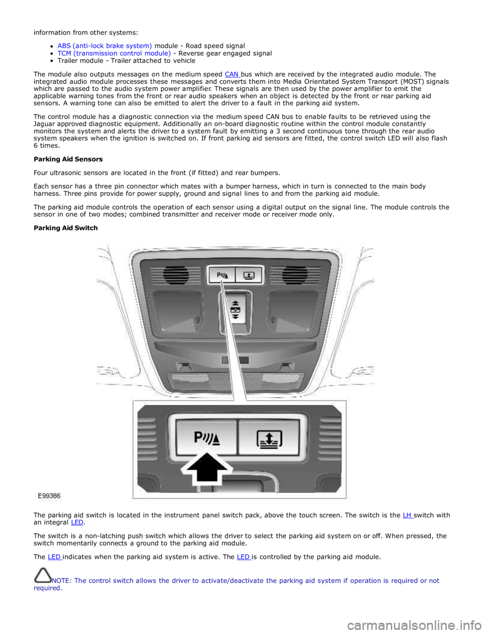
The parking aid switch is located in the instrument panel switch pack, above the touch screen. The switch is the LH switch with an integral LED.
The switch is a non-latching push switch which allows the driver to select the parking aid system on or off. When pressed, the
switch momentarily connects a ground to the parking aid module.
The LED indicates when the parking aid system is active. The LED is controlled by the parking aid module.
NOTE: The control switch allows the driver to activate/deactivate the parking aid system if operation is required or not
required.
Page 1849 of 3039
PARKING AID CAMERA
The parking aid camera receives an ignition power mode 6 power supply from the RJB. It also has a LIN bus connection with the RJB, which is used as a gateway. A shielded co-axial cable connection between the camera and the TSD is used for the video image transmission.
The camera receives power at all times when the ignition is in power mode 6. When reverse gear is selected, the RJB transmits a reverse selected message on the medium speed CAN bus. The information and entertainment module transfers the message on the MOST ring to the TSD, which displays the video input from the parking aid camera in preference to the parking
aid alert screen.
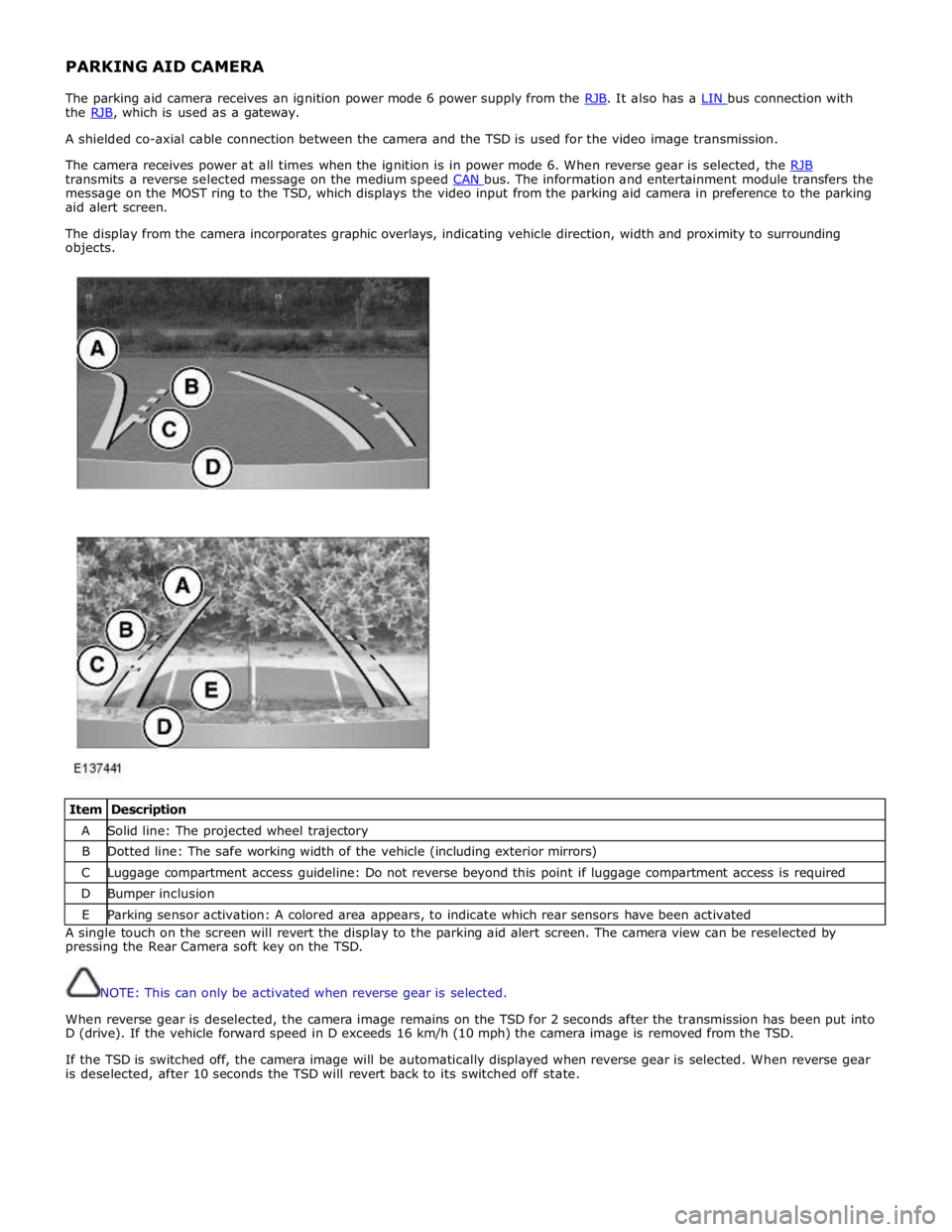
The display from the camera incorporates graphic overlays, indicating vehicle direction, width and proximity to surrounding
objects.
Item Description A Solid line: The projected wheel trajectory B Dotted line: The safe working width of the vehicle (including exterior mirrors) C Luggage compartment access guideline: Do not reverse beyond this point if luggage compartment access is required D Bumper inclusion E Parking sensor activation: A colored area appears, to indicate which rear sensors have been activated A single touch on the screen will revert the display to the parking aid alert screen. The camera view can be reselected by
pressing the Rear Camera soft key on the TSD.
NOTE: This can only be activated when reverse gear is selected.
When reverse gear is deselected, the camera image remains on the TSD for 2 seconds after the transmission has been put into
D (drive). If the vehicle forward speed in D exceeds 16 km/h (10 mph) the camera image is removed from the TSD.
If the TSD is switched off, the camera image will be automatically displayed when reverse gear is selected. When reverse gear
is deselected, after 10 seconds the TSD will revert back to its switched off state.
Page 1850 of 3039
Parking Aid - Parking Aid
Diagnosis and Testing
Principles of Operation Published: 24-Feb-2014
For a detailed description of the parking aid system, characteristics and limitations refer to the relevant description and
operation section in the workshop manual.
REFER to: Parking Aid (413-13 Parking Aid, Description and Operation).
Parking Aid System On-Board Self-Test
As part of the strategy of the system if any DTCs are detected, a long high-pitched tone approx 3 seconds will sound and the
parking aid switch (where fitted) indicator LED will flash 6 times at ignition on
If a fault is present when the parking aid system is activated then the parking aid switch (where fitted) status LED will
flash 6 times indicating an issue with front or rear parking aid sensors, wiring switch, parking aid control module or hard
wired sounders
The rear parking aid sounder/rear audio system will emit an error tone for approx 3 seconds at ignition on if a fault is
detected with the front or rear sensors, the switch, or if there is a controller area network (CAN) bus error
(Only applicable to vehicles fitted with front parking aid and a hard wired rear parking aid sounder). If there is a fault
with the rear parking aid sounder the error tone will come from the front parking aid sounder unit (integral with the
instrument cluster)
Audible and Visual Warnings when Parking Aid System is in Error State
Rear Parking Aid
System Fitted and
No Parking Aid
System Switch
Fitted
Rear Parking Aid System Fitted and Parking Aid System Switch Fitted
Front and Rear Parking Aid System Fitted with Parking Aid System Switch Fitted A long high-pitched
error tone will
sound at Ignition
On for approx 3
seconds
A long high-pitched error tone will sound at
ignition on for approx 3 seconds and the
parking aid switch indicator LED will flash 6
times at ignition on. Every time the parking
aid system is activated within the same
ignition cycle, parking aid switch indicator
LED will flash 6 times
A long high-pitched error tone will sound at
ignition on for approximately 3 seconds and
the parking aid switch indicator LED will flash 6
times at ignition on. Every time the parking aid
system is activated within the same ignition
cycle the parking aid switch indicator LED will
flash 6 times Inspection and Verification
CAUTIONS:
If the control module or a component is suspect and the vehicle remains under manufacturer warranty, refer to the
warranty policy and procedures manual (section B1.2), or determine if any prior approval programme is in operation, prior to
the installation of a new module/component.
Diagnosis by substitution from a donor vehicle is NOT acceptable. Substitution of control modules does not guarantee
confirmation of a fault, and may also cause additional faults in the vehicle being tested and/or the donor vehicle
Do not apply any grease based products to any parking aid system connector or pins
NOTE: Check DDW for open campaigns. Refer to the corresponding bulletins and SSMs which may be valid for the specific
customer complaint and carry out the recommendations as required.
1. Verify the customer concern
2. Visually inspect for obvious signs of mechanical or electrical damage
3. Ensure that the parking aid sensor face is clear of contamination that could affect the performance of the sensor
Visual Inspection
Mechanical Electrical
Parking aid sensor condition/damaged
Parking aid sensor installation and holder
Parking aid sensor alignment
Parking aid sensor contamination
Bumper cover(s)
Vehicle ride height
Non standard/non manufacturer approved accessories fitted
Battery
Fuse(s)
Relays
Wiring harness
Electrical connector(s)
Front parking aid sensor(s)
Rear parking aid sensor(s)
Parking aid switch and LED
Page 1866 of 3039
Published: 07-Aug-2014
Battery and Charging System - General Information - Battery Care
Requirements
Description and Operation
1. INTRODUCTION
This document defines the requirements for care and maintenance of batteries, and the standard of battery care at dealers and
retailers for new vehicles.
This applies to all types of 12 Volt Lead Acid Batteries used in Jaguar and Land Rover vehicles whether they are conventional
flooded technology or Absorbed Glass Mat (AGM – also known as Valve Regulated Lead Acid (VRLA)) technology and also
applies to both Primary, Secondary and Auxiliary Batteries. AGM batteries offer improved resistance to cycling as seen in stop
start applications.
In order to prevent damage to the battery and ensure a satisfactory service life, all processes detailed within this document
must be rigorously adhered to.
It is equally important therefore to note the following key points:
All new vehicles leave the factory with either a transit relay installed and/or have a transit mode programmed into the
vehicle control modules. The transit relay must be removed and the transit mode disabled (where applicable) using an
approved diagnostic system, NOT MORE THAN 72 HOURS before the customer takes delivery.
The battery can be discharged by the following mechanisms:
- Self Discharge: - A lead acid battery will very slowly discharge itself due to its own internal chemical processes
whether it is connected to a vehicle or not.
- Quiescent Discharge: - The vehicle electrical systems when connected to the battery will draw charge from the
battery.
12 Volt Lead Acid Batteries rely on internal chemical processes to create a voltage and deliver current. These processes and
the internal chemical structure of the battery can be damaged if the battery is allowed to discharge over a number of weeks /
months, or is left in a discharged state for a lengthy time period.
On vehicles with conventional ignition keys, these must not be left in the ignition lock barrel when the transit relay
has been removed, otherwise quiescent current will increase and the battery will discharge more rapidly.
For keyless vehicles, the Smart Key must be stored at least 5m (16 ft) away from the vehicle when the vehicle is
parked or stored.
AGM Batteries are fully sealed and cannot have the electrolyte level topped up.
NOTE: Dealers and retailers involved in the storage / handling of vehicles and replacement batteries have a responsibility
to ensure that only a fully charged battery may be processed through the distribution selling chain.
2. GENERAL RULES FOR BATTERY CARE
2.1 Dealer Demonstration Vehicles
Vehicles used as dealer demonstrator(s), in a showroom, must be connected to a JLR approved showroom conditioner capable
of delivering 50 Amps. This will prevent the battery from being damaged.
2.2 Software Reflash, SDD work or Ignition On related workshop activities
Due to the high electrical current demand and high depth of discharge that can occur during vehicle software re-flash activities,
SDD work or ignition on (power mode 6) related work in the workshop, vehicles that are undergoing such activities MUST have a
JLR approved power supply capable of delivering 50 Amps or more.
2.3 Extended Vehicle Rework
For any extended vehicle rework that results in consuming vehicle power, either the battery should be disconnected or a JLR
approved power supply connected.
2.4 Jump Starting New vehicles before they have been delivered to the customer
It is the dealer / retailers responsibility to make sure the battery is not allowed to discharge by following the
instructions and processes defined in this manual.
However, if circumstances dictate that a new vehicle must be jump started due to a discharged battery whilst the
vehicle is in the dealer / retailers care, the battery on this vehicle must be replaced with a new one prior to delivery
to the customer at the dealer / retailers liability.
The vehicle should also undergo investigation as to why the battery became discharged.
Do not connect the jump starting cable to the negative (-) terminal of the battery. Always connect to the recommended
earth point. As defined in the owners handbook or service documentation for that vehicle. 2.5 AGM Batteries
AGM batteries must not be charged above 14.8 Volts. Doing so will damage them.
AGM Batteries must be tested with a capable battery tester as detailed in the Equipment section (Section 5) of this
Page 1867 of 3039
procedure.
NOTE: Under no circumstances should the battery be disconnected with the engine running because under these
conditions the generator can give a very high output voltage. This high transient voltage will damage the electronic
components in the vehicle. Loose or incomplete battery connections may also cause high transient voltage.
3. HEALTH AND SAFETY PRECAUTIONS
WARNINGS:
BATTERY CELLS CONTAIN SULPHURIC ACID AND EXPLOSIVE MIXTURES OF HYDROGEN AND OXYGEN GASES. IT IS
THEREFORE ESSENTIAL THAT THE FOLLOWING SAFETY PRECAUTIONS ARE OBSERVED.
Batteries emit highly explosive hydrogen at all times, particularly during charging. To prevent any potential form of
ignition occurring when working in the vicinity of a battery:
Do not smoke when working near batteries.
Avoid sparks, short circuits or other sources of ignition in the battery vicinity.
Switch off current before making or breaking electrical connections.
Ensure battery charging area is well ventilated.
Ensure the charger is switched off when: a) connecting to a battery; b) disconnecting from the battery.
Always disconnect the ground cable from the battery terminal first and reconnect it last.
Batteries contain poisonous and highly corrosive acid. To prevent personal injury, or damage to clothing or the vehicle,
the following working practices should be followed when topping up, checking electrolyte specific gravity, removal, refitting or
carrying batteries:
Always wear suitable protective clothing (an apron or similar), safety glasses, a face mask and suitable gloves.
If acid is spilled or splashed onto clothing or the body, it must be neutralized immediately and then rinsed with clean
water. A solution of baking soda or household ammonia and water may be used as a neutralizer.
In the event of contact with the skin, drench the affected area with water. In the case of contact with the eyes, bathe
the affected area with cool clean water for approximately 15 minutes and seek urgent medical attention.
If battery acid is spilled or splashed on any surface of a vehicle, it should be neutralized and rinsed with clean water.
Heat is generated when acid is mixed with water. If it becomes necessary to prepare electrolyte of a desired specific
gravity, SLOWLY pour the concentrated acid into water (not water into acid), adding small amounts of acid while
stirring. Allow the electrolyte to cool if noticeable heat develops. With the exception of lead or lead-lined containers,
always use non-metallic receptacles or funnels. Do not store acid in excessively warm locations or in direct sunlight.
Due to their hazardous contents, the disposal of batteries is strictly controlled. When a battery is scrapped, ensure it is
disposed of safely, complying with local environmental regulations. If in doubt, contact your local authority for advice on
disposal facilities.
4. BATTERY CARE REQUIREMENTS
4.1 RECEIPT OF A NEW VEHICLE
Within 24 hours of receipt of a new vehicle, a battery condition check must be carried out in accordance with the battery test
process utilizing a JLR approved tester as outlined in the Equipment section (Section 5) of this procedure.
NOTE: The Midtronics code from the tester must be recorded on the form.
Any actions must be carried out in accordance with the table shown in the Determining Battery Condition section (Section 6)
of this procedure. The details must be recorded on the New Vehicle Storage Form which is part of the new vehicle storage
document.
For additional information, refer to: New Vehicle Storage Form (100-11 Vehicle Transportation Aids and Vehicle Storage, Description and Operation).
4.2 NEW VEHICLE STORAGE
If the vehicle is to be stored the transit relays MUST be refitted and / or the vehicle put into transport mode.
Transit relay removal / vehicle placed in normal mode should only be completed a maximum of 72 hours prior to handover to
customer
For vehicles without either a transit mode or transit relay the battery negative cable must be DISCONNECTED from the battery.
The battery must be tested and/or re-charged every 30 days and MUST be re-charged after every 90 day period.
NOTE: The Midtronics code from the tester must be recorded on the form. www.JagDocs.com