2010 INFINITI QX56 diagram
[x] Cancel search: diagramPage 3485 of 4210
SN
POWER SUPPLY AND GROUND CIRCUITSN-13
< COMPONENT DIAGNOSIS >
C
DE
F
G H
I
J
K L
M B A
O P
COMPONENT DIAGNOSIS
POWER SUPPLY AND GROUND CIRCUIT
Diagnosis Procedure (With Rear Sonar System)INFOID:0000000005146194
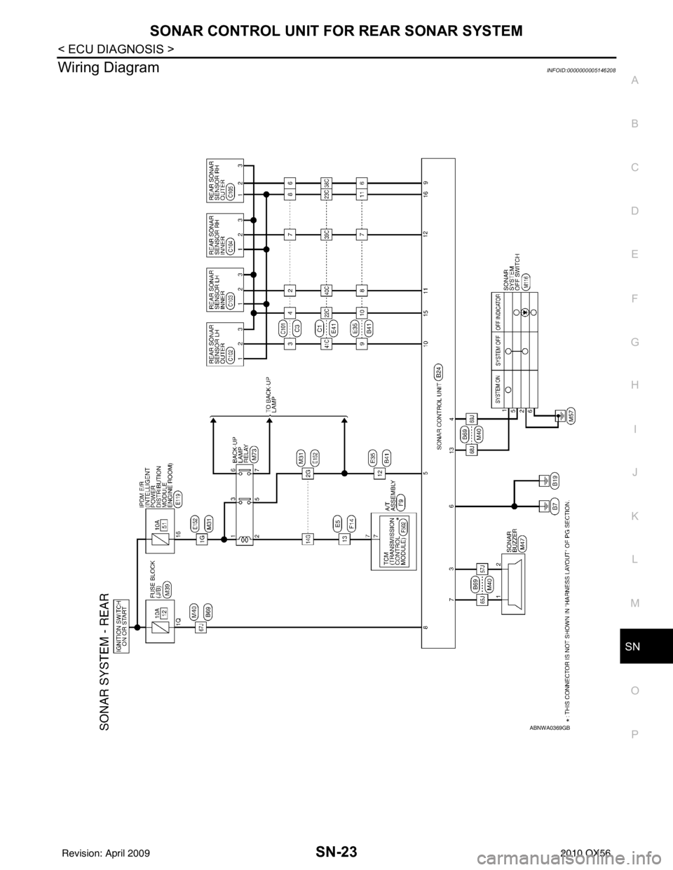
Regarding Wiring Diagram information, refer to SN-23, "Wiring Diagram".
INSPECTION FOR POWER SUPPLY AND GROUND CIRCUIT
1.CHECK FUSES
Check for blown rear sonar system fuses.
Are any fuses blown?
YES >> If fuse is blown, be sure to eliminate cause of malfunction before installing new fuse. Refer to GI-
41, "Circuit Inspection".
NO >> GO TO 2.
2.CHECK POWER SUPPLY CIRCUIT
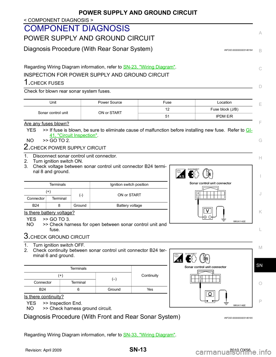
1. Disconnect sonar control unit connector.
2. Turn ignition switch ON.
3. Check voltage between sonar control unit connector B24 termi- nal 8 and ground.
Is there battery voltage?
YES >> GO TO 3.
NO >> Check harness for open between sonar control unit and fuse.
3.CHECK GROUND CIRCUIT
1. Turn ignition switch OFF.
2. Check continuity between sonar control unit connector B24 ter- minal 6 and ground.
Is there continuity?
YES >> Inspection End.
NO >> Check harness ground circuit.
Diagnosis Procedure (With Front and Rear Sonar System)INFOID:0000000005146195
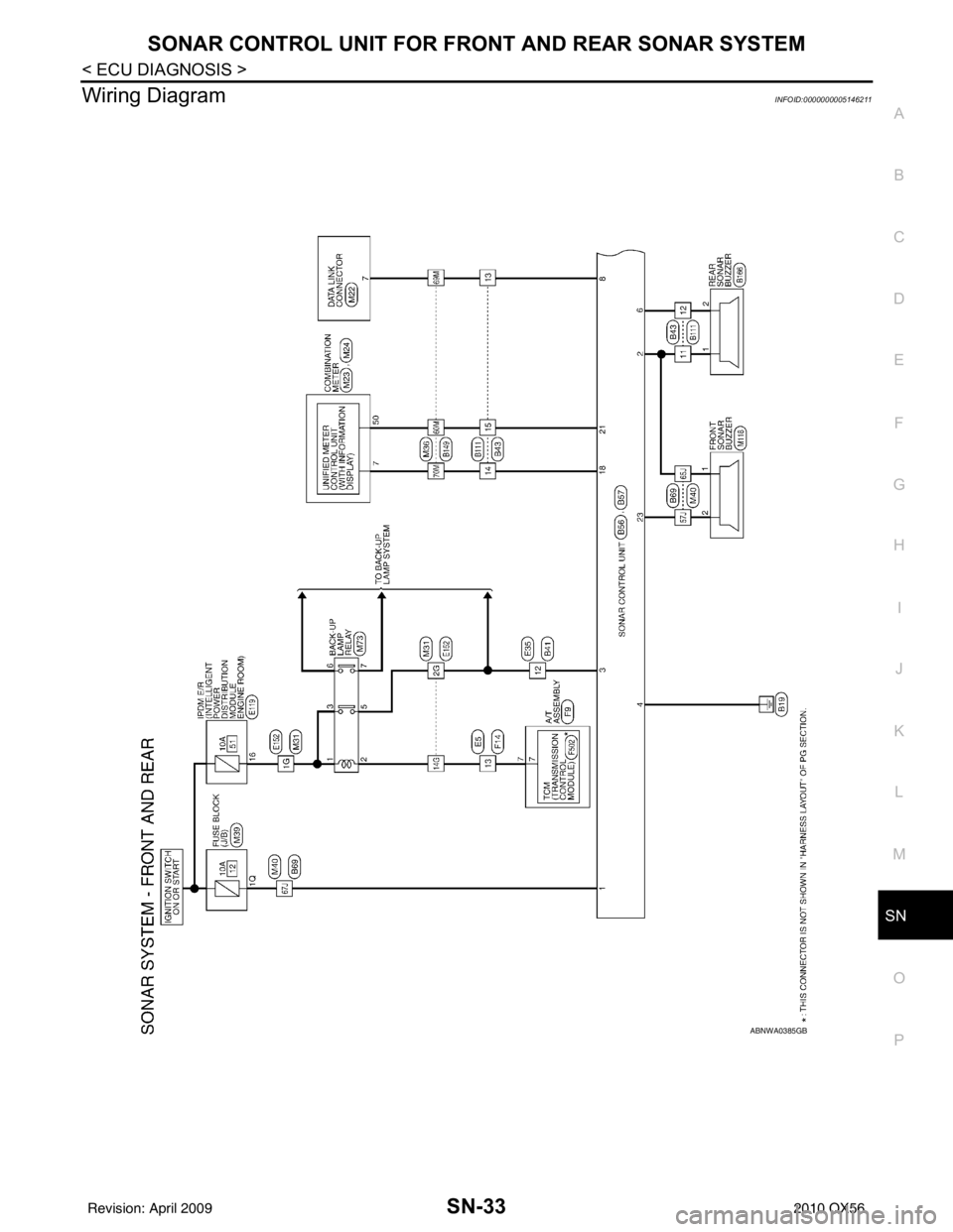
Regarding Wiring Diagram information, refer to SN-33, "Wiring Diagram".
UnitPower Source FuseLocation
Sonar control unit ON or START 12
Fuse block (J/B)
51 IPDM E/R
Terminals Ignition switch position
(+) (-) ON or START
Connector Terminal
B24 8 Ground Battery voltage
WKIA1145E
Te r m i n a l s
Continuity
(+)
(–)
Connector Terminal
B24 6 Ground Yes
WKIA1146E
Revision: April 20092010 QX56
Page 3487 of 4210
SN
SONAR SENSOR CIRCUIT INSPECTIONSN-15
< COMPONENT DIAGNOSIS >
C
DE
F
G H
I
J
K L
M B A
O P
SONAR SENSOR CIRCUIT INSPECTION
DescriptionINFOID:0000000005146196
With power and ground supplied to the sonar sensors, the sonar sensors transmit an ultrasonic signal. This
signal is reflected back to the sensor by objec ts large enough and close enough to be detected. The sonar
sensors measure the time from the transmitted signal to the time the signal is reflected back and send this
information to the sonar control unit.
Diagnosis Procedure (With Rear Sonar System)INFOID:0000000005146197
Regarding Wiring Diagram information, refer to SN-23, "Wiring Diagram".
1.CHECK REAR SONAR SENSOR CIRCUITS
1. Turn ignition switch OFF.
2. Disconnect sonar control unit connector and rear sonar sensor connectors.
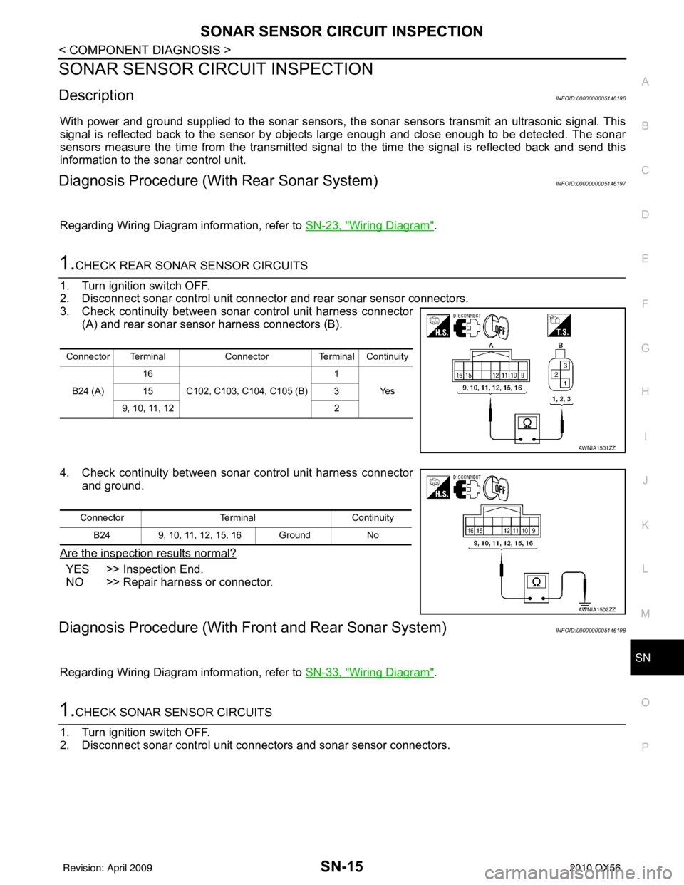
3. Check continuity between sonar control unit harness connector (A) and rear sonar sensor harness connectors (B).
4. Check continuity between sonar control unit harness connector and ground.
Are the inspection results normal?
YES >> Inspection End.
NO >> Repair harness or connector.
Diagnosis Procedure (With Front and Rear Sonar System)INFOID:0000000005146198
Regarding Wiring Diagram information, refer to SN-33, "Wiring Diagram".
1.CHECK SONAR SENSOR CIRCUITS
1. Turn ignition switch OFF.
2. Disconnect sonar control unit connec tors and sonar sensor connectors.
Connector TerminalConnectorTerminal Continuity
B24 (A) 16
C102, C103, C104, C105 (B) 1
Ye s
15 3
9, 10, 11, 12 2
AWNIA1501ZZ
ConnectorTerminalContinuity
B24 9, 10, 11, 12, 15, 16 Ground No
AWNIA1502ZZ
Revision: April 20092010 QX56
Page 3489 of 4210
SN
SONAR BUZZER CIRCUIT INSPECTIONSN-17
< COMPONENT DIAGNOSIS >
C
DE
F
G H
I
J
K L
M B A
O P
SONAR BUZZER CIRCUIT INSPECTION
DescriptionINFOID:0000000005146199
When the A/T selector lever is not it park or neutral, a stationary object will be detected by the sonar sensors
causing the front or rear sonar buzzer to sound a tone. As the vehicle moves closer to the object, the rate of
the tone will increase. When the object is very cl ose to the vehicle, the tone will sound continuously.
Diagnosis Procedure (With Rear Sonar System)INFOID:0000000005146200
Regarding Wiring Diagram information, refer to SN-23, "Wiring Diagram".
1.CHECK SONAR BUZZER
Refer to SN-18, "
Component Inspection".
Is the inspection result normal?
YES >> GO TO 2.
NO >> Replace sonar buzzer. Refer to SN-51, "
Removal and Installation".
2.CHECK SONAR BUZZER CIRCUITS
1. Turn ignition switch OFF.
2. Disconnect sonar control unit connector and sonar buzzer connector.
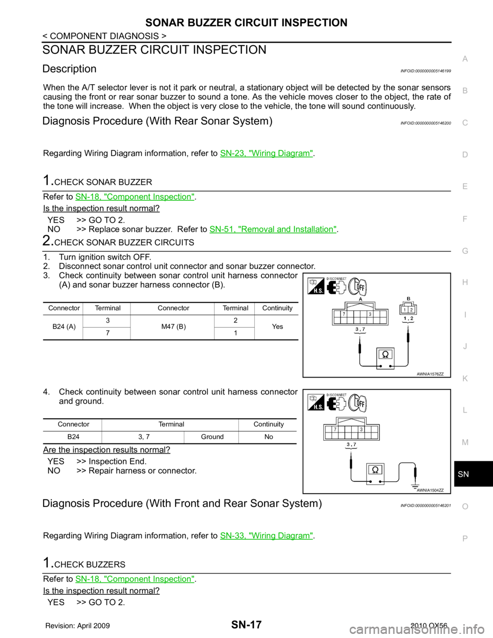
3. Check continuity between sonar control unit harness connector (A) and sonar buzzer harness connector (B).
4. Check continuity between sonar control unit harness connector and ground.
Are the inspection results normal?
YES >> Inspection End.
NO >> Repair harness or connector.
Diagnosis Procedure (With Front and Rear Sonar System)INFOID:0000000005146201
Regarding Wiring Diagram information, refer to SN-33, "Wiring Diagram".
1.CHECK BUZZERS
Refer to SN-18, "
Component Inspection".
Is the inspection result normal?
YES >> GO TO 2.
Connector Terminal Connector Terminal Continuity
B24 (A) 3
M47 (B) 2
Ye s
71
AWNIA1576ZZ
Connector TerminalContinuity
B24 3, 7Ground No
AWNIA1504ZZ
Revision: April 20092010 QX56
Page 3491 of 4210
SN
SONAR SYSTEM OFF SWITCH CIRCUIT INSPECTIONSN-19
< COMPONENT DIAGNOSIS >
C
DE
F
G H
I
J
K L
M B A
O P
SONAR SYSTEM OFF SWITCH CIRCUIT INSPECTION
DescriptionINFOID:0000000005146203
The sonar system can be disabled by momentarily pressing the sonar system OFF switch. The sonar system
OFF indicator lamp will be illuminated when the sonar s ystem is OFF. Enabling the sonar system will cause
the sonar system OFF indicator to go out. The indica tor will flash if a malfunction exists in the system.
Diagnosis Procedure (With Rear Sonar System)INFOID:0000000005146204
Regarding Wiring Diagram information, refer to SN-23, "Wiring Diagram".
1.CHECK SONAR SYSTEM OFF SWITCH
Refer to SN-20, "
Component Inspection".
Is the inspection result normal?
YES >> GO TO 2.
NO >> Replace sonar system OFF switch. Refer to IP-14, "
Removal and Installation".
2.CHECK SONAR SYSTEM OFF SWITCH CIRCUITS
1. Turn ignition switch OFF.
2. Disconnect sonar control unit connector and sonar system OFF switch connector.
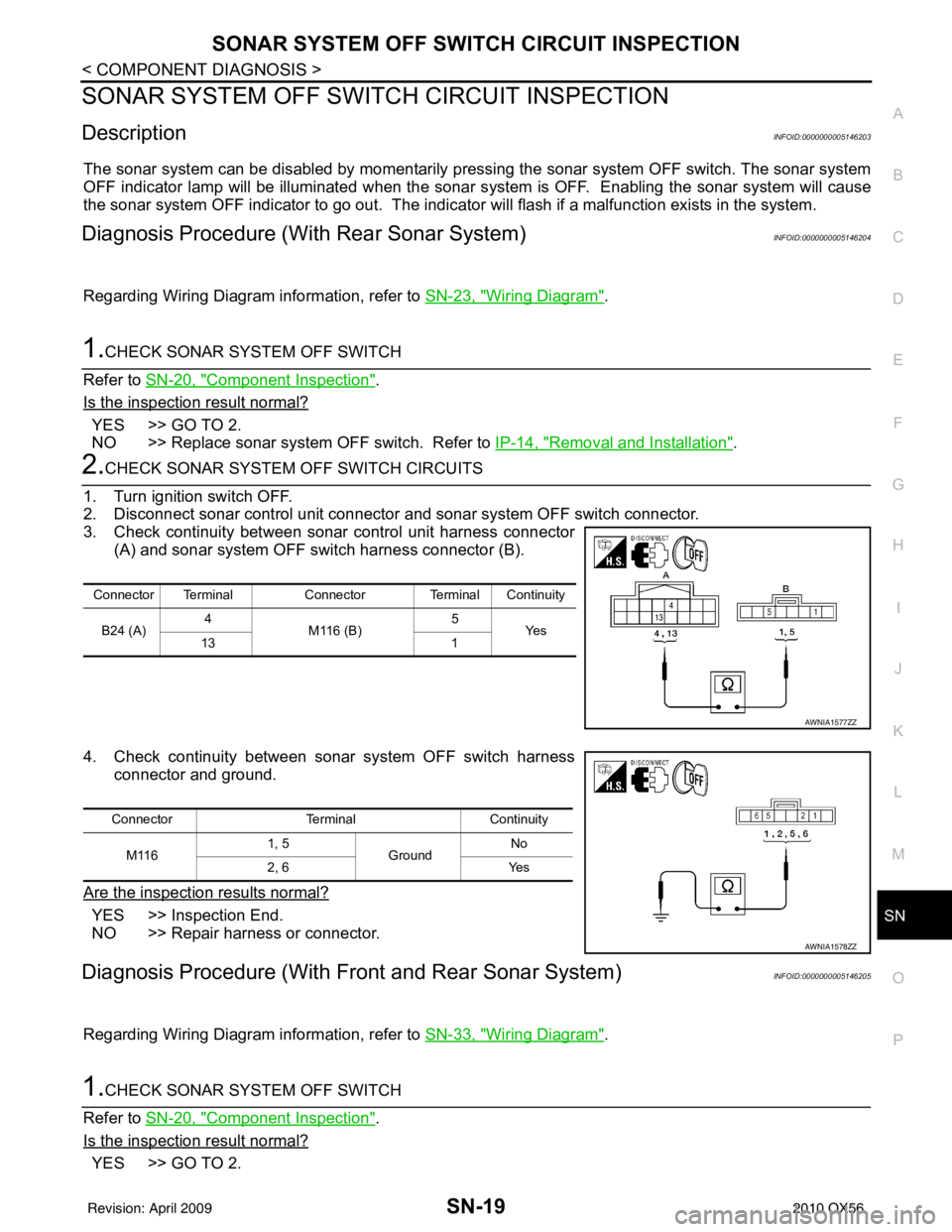
3. Check continuity between sonar control unit harness connector (A) and sonar system OFF switch harness connector (B).
4. Check continuity between sonar system OFF switch harness connector and ground.
Are the inspection results normal?
YES >> Inspection End.
NO >> Repair harness or connector.
Diagnosis Procedure (With Front and Rear Sonar System)INFOID:0000000005146205
Regarding Wiring Diagram information, refer to SN-33, "Wiring Diagram".
1.CHECK SONAR SYSTEM OFF SWITCH
Refer to SN-20, "
Component Inspection".
Is the inspection result normal?
YES >> GO TO 2.
Connector Terminal Connector Terminal Continuity
B24 (A) 4
M116 (B) 5
Ye s
13 1
AWNIA1577ZZ
ConnectorTerminalContinuity
M116 1, 5
Ground No
2, 6 Yes
AWNIA1578ZZ
Revision: April 20092010 QX56
Page 3495 of 4210
SN
SONAR CONTROL UNIT FOR REAR SONAR SYSTEMSN-23
< ECU DIAGNOSIS >
C
DE
F
G H
I
J
K L
M B A
O P
Wiring DiagramINFOID:0000000005146208
ABNWA0369GB
Revision: April 20092010 QX56
Page 3505 of 4210
SN
SONAR CONTROL UNIT FOR FRONT AND REAR SONAR SYSTEMSN-33
< ECU DIAGNOSIS >
C
DE
F
G H
I
J
K L
M B A
O P
Wiring DiagramINFOID:0000000005146211
ABNWA0385GB
Revision: April 20092010 QX56
Page 3547 of 4210
SRC-1
RESTRAINTS
C
DE
F
G
I
J
K L
M
SECTION SRC
A
B
SRC
N
O P
CONTENTS
SRS AIRBAG CONTROL SYSTEM
BASIC INSPECTION ....... .............................3
DIAGNOSIS AND REPAIR WORK FLOW .... .....3
Work Flow ........................................................... ......3
INTERMITTENTS INCIDENT ..............................5
Inspection Procedure ......................................... ......5
Trouble Diagnosis with CONSULT-III .......................5
FUNCTION DIAGNOSIS ...............................6
SRS AIR BAG SYSTEM ................................. .....6
SRS Configuration .............................................. ......6
SRS Component Parts Location ...............................7
Driver Air Bag Module ...............................................7
Front Passenger Air Bag Module ..............................8
Front Side Air Bag ............................................... ......8
Side Curtain Air Bag ..................................................8
Front Seat Belt Pre-tensioner with Load Limiter .......8
Direct-connect SRS Component Connectors ............9
OCCUPANT CLASSIFICATION SYSTEM .........10
System Diagram .................................................. ....10
Occupant Classification System (OCS) ..................10
PASSENGER SEAT BELT WARNING SYS-
TEM ....................................................................
12
System Diagram .................................................. ....12
System Description .................................................12
Component Parts Location ......................................12
ON BOARD DIAGNOSTIC (OBD) SYSTEM ......13
Trouble Diagnosis Introduction ........................... ....13
SRS Operation Check .............................................13
Trouble Diagnosis without CONSULT-III ................15
CONSULT-III Function (AIR BAG) ..........................15
Self-Diagnosis Function (Without CONSULT-III) ....15
COMPONENT DIAGNOSIS .........................17
B1049 – B1052, B1054 – B1057 DRIVER AIR-
BAG MODULE ...................................................
17
Description ........................................................... ....17
DTC Logic ................................................................17
Diagnosis Procedure (Component Diagnosis) ........18
B1065 – B1068, B1070 – B1073 PASSEN-
GER AIRBAG MODULE ...................................
20
Description ...............................................................20
DTC Logic ................................................................20
Diagnosis Procedure (Component Diagnosis) ........21
B1134 – B1137 SIDE AIRBAG MODULE LH ...23
Description ...............................................................23
DTC Logic ................................................................23
Diagnosis Procedure (Component Diagnosis) ........24
B1129 – B1132 SIDE AIRBAG MODULE RH ...26
Description ...............................................................26
DTC Logic ................................................................26
Diagnosis Procedure (Component Diagnosis) ........27
B1198 – B1201 SIDE CURTAIN AIR BAG
MODULE LH (FRONT) ......................................
29
Description ...............................................................29
DTC Logic ................................................................29
Diagnosis Procedure (Component Diagnosis) ........30
B1193 – B1196 SIDE CURTAIN AIR BAG
MODULE RH (FRONT) .....................................
32
Description ...............................................................32
DTC Logic ................................................................32
Diagnosis Procedure (Component Diagnosis) ........33
B1150 – B1153 SIDE CURTAIN AIR BAG
MODULE LH (REAR) ........................................
35
Description ...............................................................35
DTC Logic ................................................................35
Diagnosis Procedure (Component Diagnosis) ........36
B1145 – B1148 SIDE CURTAIN AIR BAG
MODULE RH (REAR) .......................................
38
Description ...............................................................38
DTC Logic ................................................................38
Revision: April 20092010 QX56
Page 3548 of 4210

SRC-2
Diagnosis Procedure (Component Diagnosis) ........39
B1086 – B1089 SEAT BELT PRE-TENSION-
ER LH .................................................................
41
Description ........................................................... ...41
DTC Logic ...............................................................41
Diagnosis Procedure (Component Diagnosis) ........42
B1081 – B1084 SEAT BELT PRE-TENSION-
ER RH ................................................................
44
Description ..............................................................44
DTC Logic ...............................................................44
Diagnosis Procedure (Component Diagnosis) ........45
B1182 - B1185 SEAT BELT BUCKLE PRE-
TENSIONER LH .................................................
47
Description ........................................................... ...47
DTC Logic ...............................................................47
Diagnosis Procedure (Component Diagnosis) ........48
B1177 - B1180 SEAT BELT BUCKLE PRE-
TENSIONER RH ................................................
50
Description ........................................................... ...50
DTC Logic ...............................................................50
Diagnosis Procedure (Component Diagnosis) ........51
B1033 – B1035 CRASH ZONE SENSOR .........53
Description ........................................................... ...53
DTC Logic ...............................................................53
Diagnosis Procedure (Component Diagnosis) ........54
B1118 – B1120 SATELLITE SENSOR LH ........56
Description ........................................................... ...56
DTC Logic ...............................................................56
Diagnosis Procedure (Component Diagnosis) ........57
B1113 – B1115 SATELLITE SENSOR RH .......59
Description ........................................................... ...59
DTC Logic ...............................................................59
Diagnosis Procedure (Component Diagnosis) ........60
B1XXX AIR BAG DIAGNOSIS SENSOR UNIT ...62
Description ........................................................... ...62
DTC Logic ...............................................................62
Diagnosis Procedure (Component Diagnosis) ........63
B1023 PASSENGER AIR BAG OFF INDICA-
TOR ....................................................................
64
Description ........................................................... ...64
DTC Logic ...............................................................64
Diagnosis Procedure (Component Diagnosis) ........65
B1017 – B1022 OCCUPANT CLASSIFICA-
TION SYSTEM ................................................ ...
67
Description ........................................................... ...67
DTC Logic ...............................................................67
Diagnosis Procedure (Component Diagnosis) ........68
B1209 – B1211 COLLISION DETECTION ........70
Description ........................................................... ...70
DTC Logic ...............................................................70
Diagnosis Procedure (Component Diagnosis) ........70
ECU DIAGNOSIS .......................................71
DIAGNOSIS SENSOR UNIT .............................71
Wiring Diagram .................................................... ...71
Trouble Diagnosis with CONSULT-III .....................80
Trouble Diagnosis without CONSULT-III ................84
SYMPTOM DIAGNOSIS ............................89
SRS AIR BAG SYSTEM ................................. ...89
"AIR BAG" Warning Lamp Does Not Turn Off ..... ...89
"AIR BAG" Warning Lamp Does Not Turn On ........89
PASSENGER SEAT BELT WARNING SYS-
TEM ....................................................................
91
Seat Belt Warning System Does Not Function .... ...91
PRECAUTION ............................................92
PRECAUTIONS .............................................. ...92
Precaution for Supplemental Restraint System
(SRS) "AIR BAG" and "SEAT BELT PRE-TEN-
SIONER" .............................................................. ...
92
Precaution for SRS "AIR BAG" and "SEAT BELT
PRE-TENSIONER" Service ................................. ...
92
Occupant Classification System Precaution ...........92
Revision: April 20092010 QX56