Page 3255 of 4210
HEIGHT SENSOR SIGNAL CIRCUITSCS-23
< COMPONENT DIAGNOSIS >
C
DF
G H
I
J
K L
M A
B
SCS
N
O P
HEIGHT SENSOR SIGNAL CIRCUIT
DescriptionINFOID:0000000005148181
Supplies vehicle height input to the suspension control unit.
Component Function CheckINFOID:0000000005148182
1.CHECK HEIGHT SENSOR OPERATION
CONSULT-III
1. Select "HEIGT SEN" of AIR L EVELIZER data monitor test item.
2. While monitoring test item, add or take away weight from the rear of the vehicle. Check that the voltage value changes with vehicle height.
Is the HEIGHT SEN data monitor responding normally?
YES >> Height sensor is operating normally.
NO >> Refer to SCS-23, "
Diagnosis Procedure".
Diagnosis ProcedureINFOID:0000000005148183
Regarding Wiring Diagram information, refer to SCS-29, "Wiring Diagram".
1.CHECK HEIGHT SENSOR POWER AND GROUND SUPPLY
Check height sensor power and ground supply. Refer to SCS-18, "
HEIGHT SENSOR : Diagnosis Procedure".
Are the inspection results normal?
YES >> GO TO 2.
NO >> Repair harness or connector.
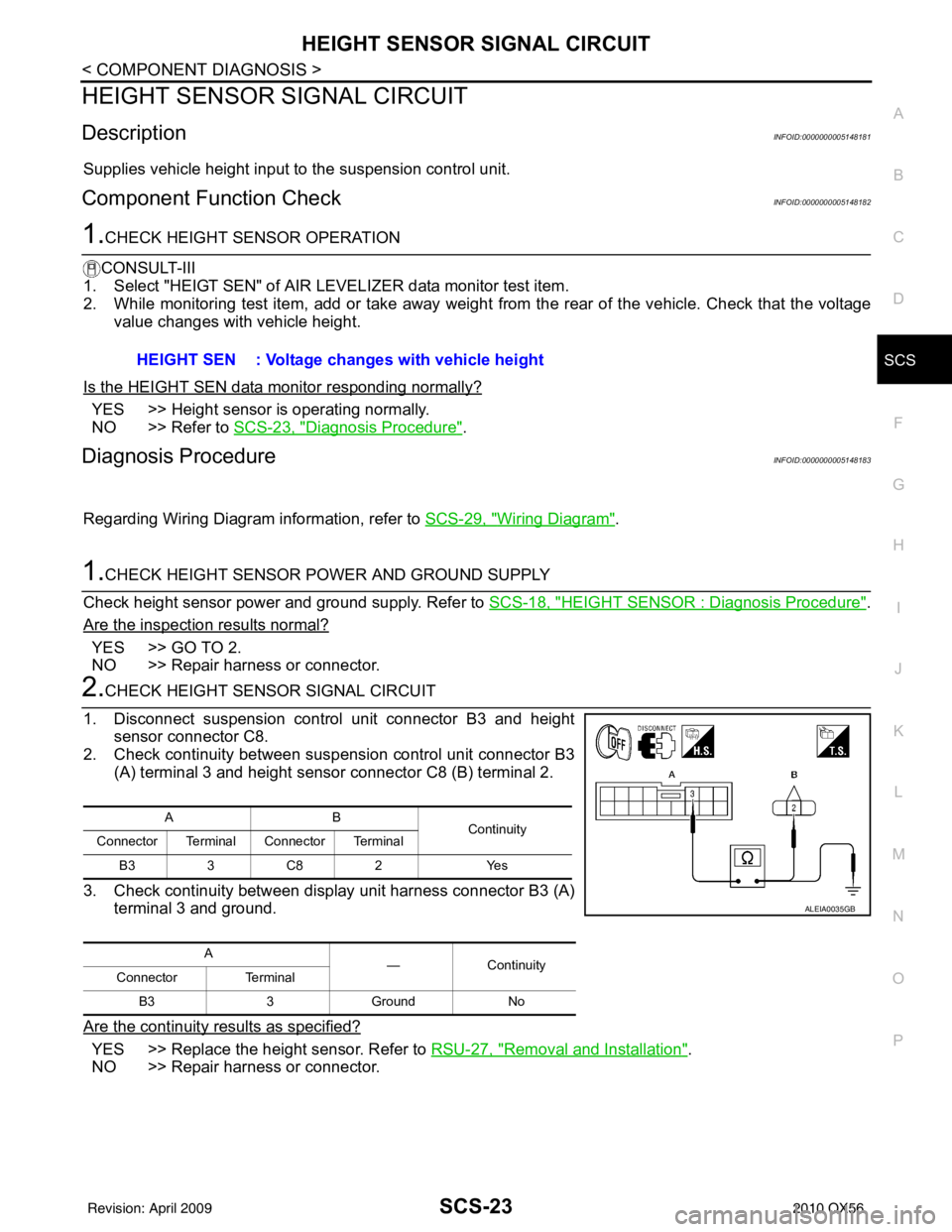
2.CHECK HEIGHT SENSOR SIGNAL CIRCUIT
1. Disconnect suspension control unit connector B3 and height sensor connector C8.
2. Check continuity between suspension control unit connector B3
(A) terminal 3 and height sensor connector C8 (B) terminal 2.
3. Check continuity between display unit harness connector B3 (A) terminal 3 and ground.
Are the continuity results as specified?
YES >> Replace the height sensor. Refer to RSU-27, "Removal and Installation".
NO >> Repair harness or connector. HEIGHT SEN : Voltage changes with vehicle height
AB
Continuity
Connector Terminal Connector Terminal
B33C 82 Y es
A —Contin u it y
Connector Terminal
B3 3Ground No
ALEIA0035GB
Revision: April 20092010 QX56
Page 3256 of 4210
SCS-24
< COMPONENT DIAGNOSIS >
EXHAUST VALVE SOLENOID CIRCUIT
EXHAUST VALVE SOLENOID CIRCUIT
DescriptionINFOID:0000000005148184
Receives exhaust valve solenoid signal from suspension control unit. When activated, the exhaust valve sole-
noid releases air pressure from the suspension control system.
Component Function CheckINFOID:0000000005148185
1.CHECK EXHAUST SOLENOID OPERATION
CAUTION:
While operating this active test, the suspension control system will vent air pressure and the vehicle
ride height will lower. Ensure th e area around the vehicle is free fr om obstructions before beginning
test.
CONSULT-III
1. Ensure the suspension control system has air pressure and is not drooping in the rear.
2. Select "EXHAUST SOLENOID" of AIR LEVELIZER active test items.
3. While operating test item, check that the exhaust valve solenoid opens to vent air from the system. The vehicle should lower when the exhaust valve solenoid is activated.
Does the system vent properly?
YES >> Exhaust valve solenoid is operating normally.
NO >> Refer to SCS-24, "
Diagnosis Procedure".
Diagnosis ProcedureINFOID:0000000005148186
Regarding Wiring Diagram information, refer to SCS-29, "Wiring Diagram".
1.CHECK EXHAUST VALVE SOLENOID SIGNAL
CONSULT-III
1. Connect suspension control unit connector B3.
2. Turn ignition switch ON.
3. Select "EXHAUST SOLENOID" of AIR LEVELIZER active test
items.
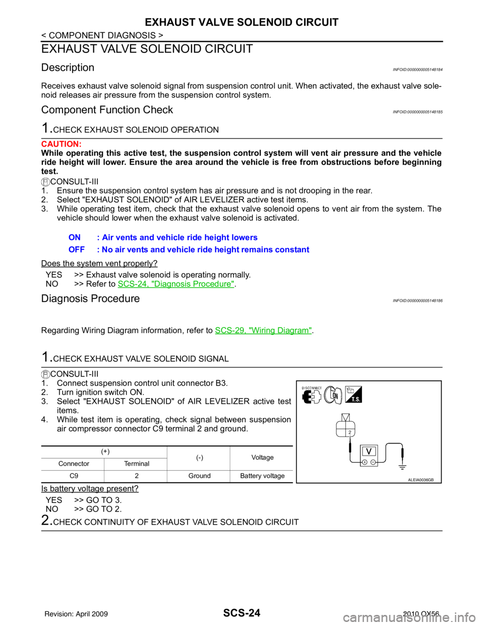
4. While test item is operating, check signal between suspension
air compressor connector C9 terminal 2 and ground.
Is battery voltage present?
YES >> GO TO 3.
NO >> GO TO 2.
2.CHECK CONTINUITY OF EXHA UST VALVE SOLENOID CIRCUIT
ON : Air vents and vehicle ride height lowers
OFF : No air vents and vehicle ride height remains constant
(+)
(-)Voltage
Connector Terminal
C9 2Ground Battery voltage
ALEIA0036GB
Revision: April 20092010 QX56
Page 3258 of 4210
SCS-26
< COMPONENT DIAGNOSIS >
CK SUSP WARNING INDICATOR CONTROL CIRCUIT
CK SUSP WARNING INDICATOR CONTROL CIRCUIT
DescriptionINFOID:0000000005148187
The CK SUSP warning lamp is controlled by a ground signal provided to the combination meter by the sus-
pension control unit.
Component Function CheckINFOID:0000000005148188
1.CHECK WARNING LAMP OPERATION
CONSULT-III
1. Turn ignition ON.
2. Select "WARNING LAMP" of AI R LEVELIZER active test items.
3. While operating test item, check that the warning lamp activates.
Does the warning lamp operate properly?
YES >> Warning lamp is operating normally.
NO >> Refer to SCS-26, "
Diagnosis Procedure".
Diagnosis ProcedureINFOID:0000000005148189
Regarding Wiring Diagram information, refer to SCS-29, "Wiring Diagram".
1.PERFORM SUSPENSION CONTROL SYSTEM SELF-DIAGNOSIS
CONSULT-III
1. Turn ignition ON.
2. Perform SELF DIAGNOSIS functi on of AIR LEVELIZER system.
Are any DTC's present?
YES >> Refer to SCS-34, "DTC Index".
NO >> • If warning lamp is always ON, GO TO 2. • If warning lamp is always OFF, GO TO 3
2.CHECK SUSPENSION CONTROL UNI T WARNING LAMP CONTROL
1. Turn ignition OFF.
2. Disconnect the suspension control unit connector B3.
3. Turn ignition ON.
Does the CK SUSP warning lamp turn ON?
YES >> GO TO 3.
NO >> Replace the suspension control unit. Refer to RSU-26, "
Removal and Installation".
3.CHECK CONTINUITY OF WARNING LAMP CONTROL CIRCUIT
1. Turn ignition switch OFF.
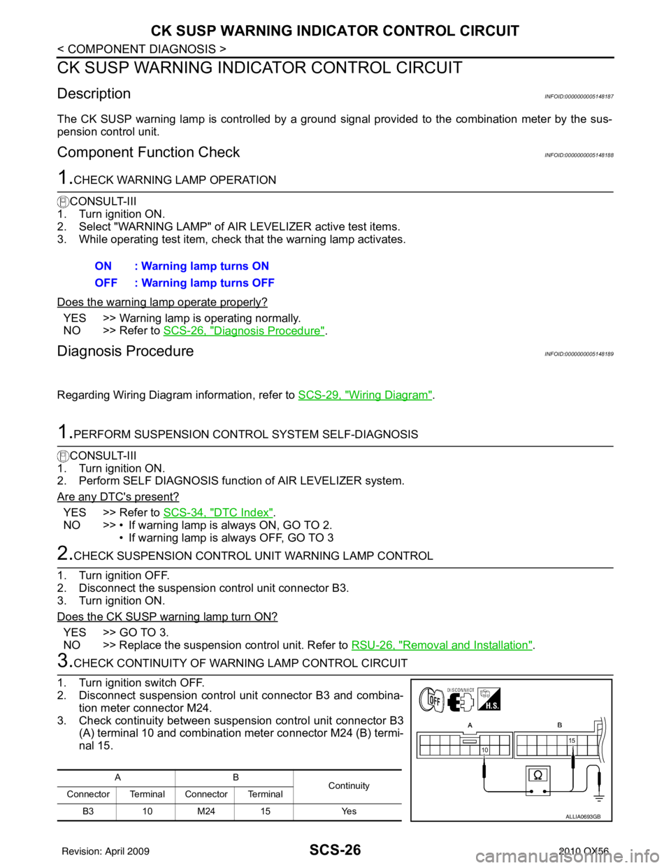
2. Disconnect suspension control unit connector B3 and combina- tion meter connector M24.
3. Check continuity between suspension control unit connector B3 (A) terminal 10 and combination meter connector M24 (B) termi-
nal 15.ON : Warning lamp turns ON
OFF : Warning lamp turns OFF
AB
Continuity
Connector Terminal Connector Terminal
B3 10 M24 15 Yes
ALLIA0693GB
Revision: April 20092010 QX56
Page 3261 of 4210
SUSPENSION CONTROL UNITSCS-29
< ECU DIAGNOSIS >
C
DF
G H
I
J
K L
M A
B
SCS
N
O P
Wiring DiagramINFOID:0000000005148191
ABEWA0028GB
Revision: April 20092010 QX56
Page 3273 of 4210
SE-1
BODY INTERIOR
C
DE
F
G H
I
K L
M
SECTION SE
A
B
SE
N
O P
CONTENTS
SEAT
BASIC INSPECTION ....... .............................3
DIAGNOSIS AND REPAIR WORKFLOW ..... .....3
Work Flow ........................................................... ......3
INSPECTION AND ADJUSTMENT .....................5
Preliminary Check ............................................... ......5
FUNCTION DIAGNOSIS ...............................6
THIRD ROW POWER FOLDING SEAT ......... .....6
System Description ............................................. ......6
Component Parts Location ........................................7
Component Description .............................................7
COMPONENT DIAGNOSIS ..........................8
POWER SEAT .....................................................8
Wiring Diagram — Passenger Side — ................ ......8
HEATED SEAT ...................................................12
Description ..............................................................12
Wiring Diagram .......................................................13
THIRD SEAT ......................................................19
Power Supply and Ground Circuit Check for Third
Row Power Folding Seat Control Unit ................. ....
19
Third Row Power Folding Seat Switch ....................20
Third Row Power Folding Seat Motor .....................20
ECU DIAGNOSIS .........................................22
THIRD ROW POWER FOLDING SEAT CON-
TROL UNIT .........................................................
22
Reference Value ................................................. ....22
Wiring Diagram .......................................................24
DTC Index ...............................................................29
Fail Safe ..................................................................30
SYMPTOM DIAGNOSIS ..............................31
THIRD ROW POWER FOLDING SEAT ......... ....31
Symptom Table ................................................... ....31
NONE OF THE THIRD ROW POWER FOLD-
ING SEATS WILL OPERATE WITH ANY
SWITCH. ............................................................
32
None of the Third Row Power Folding Seats Will
Operate With Any Third Row Power Folding Seat
Switch .................................................................. ....
32
ONLY ONE THIRD ROW POWER FOLDING
SEAT WILL OPERATE. ....................................
33
Only One Third Row Power Folding Seat Will Op-
erate .................................................................... ....
33
THIRD ROW POWER FOLDING SEAT WILL
OPERATE IN ONLY ONE DIRECTION. ...........
35
Third Row Power Folding Seat Will Operate in
Only One Direction .............................................. ....
35
THIRD ROW POWER FOLDING SEAT WILL
STOP SHORT OF IT’S FULLY UP OR DOWN
POSITION. .........................................................
37
Third Row Power Folding Seat Stops Short of it's
Fully Up or Down Position .......................................
37
THIRD ROW POWER FOLDING SEAT
MAKES EXCESSIVE NOISE WHILE MOV-
ING. ...................................................................
38
Third Row Power Folding Seat Makes Excessive
Noise While Moving ............................................. ....
38
SQUEAK AND RATTLE TROUBLE DIAG-
NOSES ..............................................................
39
Work Flow ................................................................39
Generic Squeak and Rattle Troubleshooting ...........41
Diagnostic Worksheet ..............................................43
PRECAUTION ..............................................45
PRECAUTIONS .................................................45
Precaution for Supplemental Restraint System
(SRS) "AIR BAG" and "SEAT BELT PRE-TEN-
SIONER" ............................................................. ....
45
Revision: April 20092010 QX56
Page 3280 of 4210
SE-8
< COMPONENT DIAGNOSIS >
POWER SEAT
COMPONENT DIAGNOSIS
POWER SEAT
Wiring Diagram — Passenger Side —INFOID:0000000005147384
ABJWA0030GB
Revision: April 20092010 QX56
Page 3285 of 4210
HEATED SEATSE-13
< COMPONENT DIAGNOSIS >
C
DE
F
G H
I
K L
M A
B
SE
N
O P
Wiring DiagramINFOID:0000000005147386
ABJWA0098GB
Revision: April 20092010 QX56
Page 3291 of 4210
THIRD SEATSE-19
< COMPONENT DIAGNOSIS >
C
DE
F
G H
I
K L
M A
B
SE
N
O P
THIRD SEAT
Power Supply and Ground Circu it Check for Third Row Power Folding Seat Control
Unit
INFOID:0000000005147387
Regarding Wiring Diagram information, refer to SE-24, "Wiring Diagram".
1.CHECK FUSES AND FUSIBLE LINK
Check for blown fuses or fusible link.
Are any fuses or fusible links blown?
YES >> Install new fuse. Eliminate cause of malfunction if fuse blows again.
NO >> GO TO 2
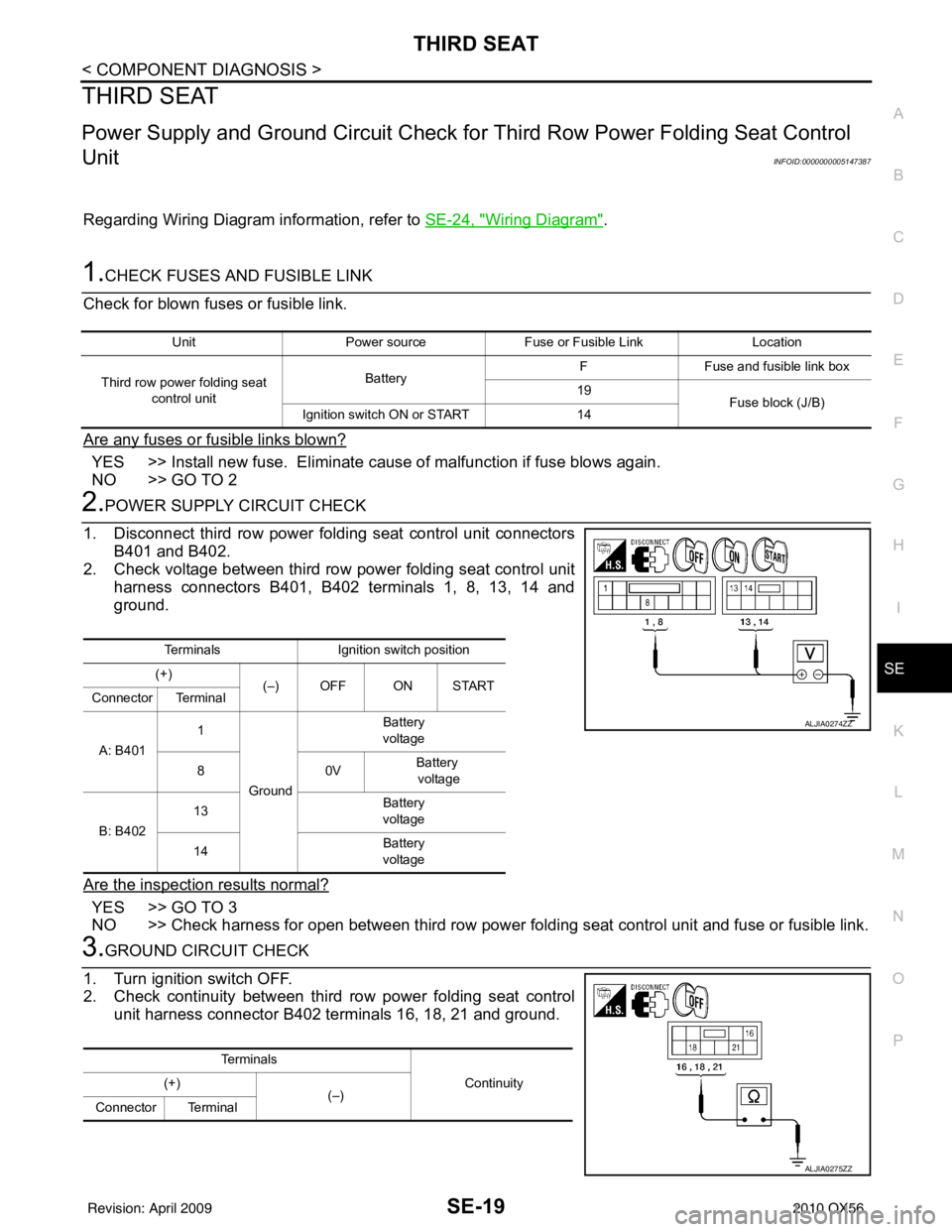
2.POWER SUPPLY CIRCUIT CHECK
1. Disconnect third row power folding seat control unit connectors B401 and B402.
2. Check voltage between third row power folding seat control unit harness connectors B401, B402 terminals 1, 8, 13, 14 and
ground.
Are the inspection results normal?
YES >> GO TO 3
NO >> Check harness for open between third row power folding seat control unit and fuse or fusible link.
3.GROUND CIRCUIT CHECK
1. Turn ignition switch OFF.
2. Check continuity between third row power folding seat control unit harness connector B402 terminals 16, 18, 21 and ground.
Unit Power source Fuse or Fusible Link Location
Third row power folding seat control unit Battery
F
Fuse and fusible link box
19 Fuse block (J/B)
Ignition switch ON or START 14
TerminalsIgnition switch position
(+) (–) OFF ON START
Connector Terminal
A: B401 1
Ground Battery
voltage
80 VBattery
voltage
B: B402 13
Battery
voltage
14 Battery
voltage
ALJIA0274ZZ
Te r m i n a l s
Continuity
(+)
(–)
Connector Terminal
ALJIA0275ZZ
Revision: April 20092010 QX56