2010 INFINITI QX56 diagram
[x] Cancel search: diagramPage 3296 of 4210
SE-24
< ECU DIAGNOSIS >
THIRD ROW POWER FOLDING SEAT CONTROL UNIT
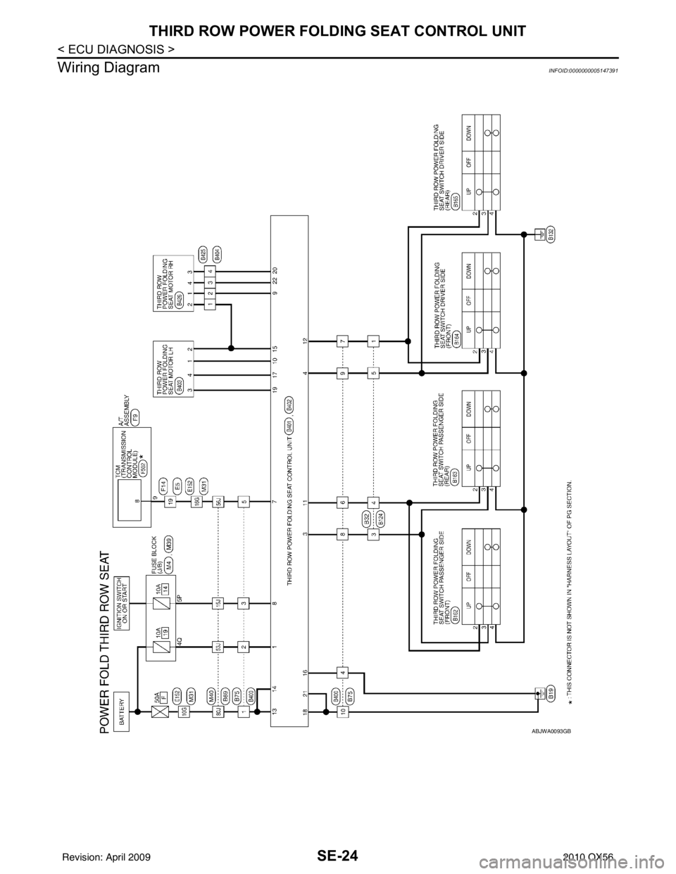
Wiring Diagram
INFOID:0000000005147391
ABJWA0093GB
Revision: April 20092010 QX56
Page 3304 of 4210
SE-32
< SYMPTOM DIAGNOSIS >
NONE OF THE THIRD ROW POWER FOLDING SEATS WILL OPERATE WITH
ANY SWITCH.
NONE OF THE THIRD ROW POWE R FOLDING SEATS WILL OPERATE
WITH ANY SWITCH.
None of the Third Row Power Folding Seat s Will Operate With Any Third Row Power
Folding Seat Switch
INFOID:0000000005147395
Regarding Wiring Diagram information, refer to SE-24, "Wiring Diagram".
1.PRELIMINARY CHECK
Perform preliminary check. Refer to SE-5, "
Preliminary Check".
Are inspection results normal?
YES >> GO TO 2.
NO >> Perform repairs as necessary.
2.THIRD ROW POWER FOLDING SEAT SWITCH GROUND
1. Turn ignition switch OFF.
2. Disconnect any third row power folding seat switch connector.
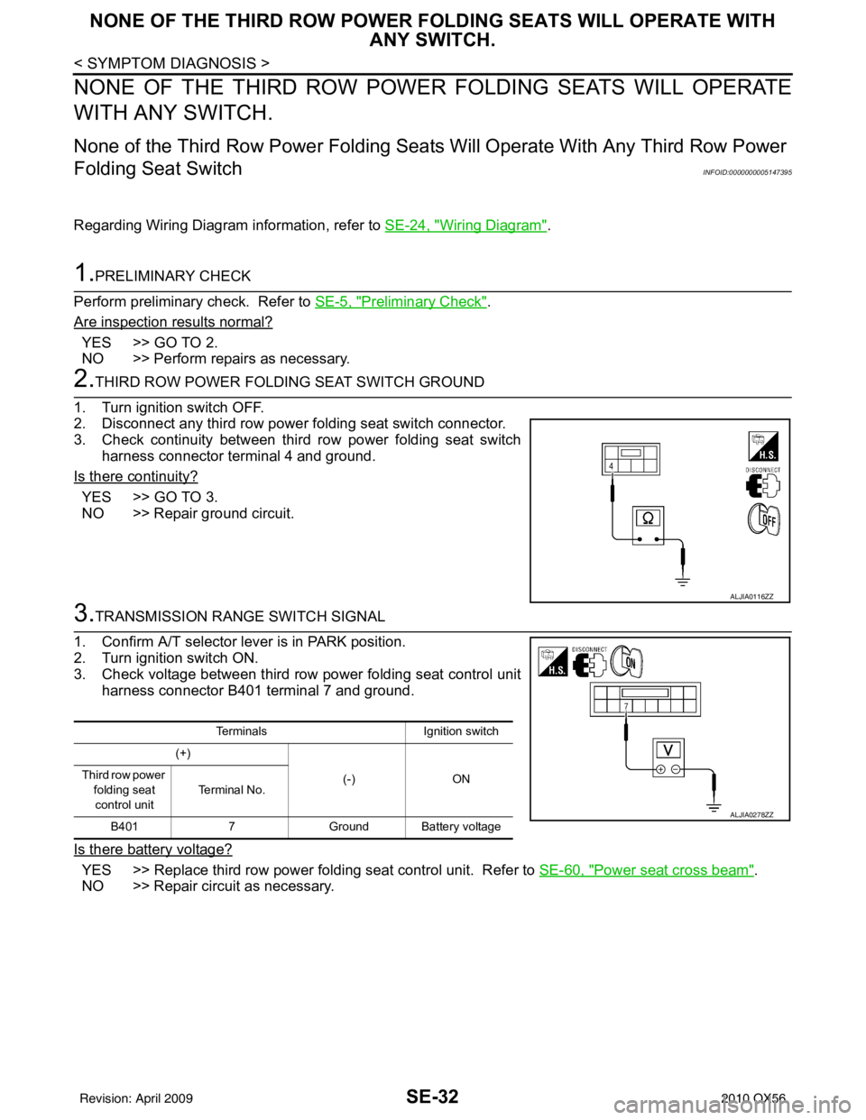
3. Check continuity between third row power folding seat switch harness connector terminal 4 and ground.
Is there continuity?
YES >> GO TO 3.
NO >> Repair ground circuit.
3.TRANSMISSION RANGE SWITCH SIGNAL
1. Confirm A/T selector lever is in PARK position.
2. Turn ignition switch ON.
3. Check voltage between third row power folding seat control unit harness connector B401 terminal 7 and ground.
Is there battery voltage?
YES >> Replace third row power folding seat control unit. Refer to SE-60, "Power seat cross beam".
NO >> Repair circuit as necessary.
ALJIA0116ZZ
Terminals Ignition switch
(+)
(-)ON
Third row power
folding seat
control unit Te r m i n a l N o .
B401 7Ground Battery voltage
ALJIA0278ZZ
Revision: April 20092010 QX56
Page 3305 of 4210
ONLY ONE THIRD ROW POWER FOLDING SEAT WILL OPERATE.SE-33
< SYMPTOM DIAGNOSIS >
C
DE
F
G H
I
K L
M A
B
SE
N
O P
ONLY ONE THIRD ROW POWER FOLDING SEAT WILL OPERATE.
Only One Third Row Power Folding Seat Will OperateINFOID:0000000005147396
Regarding Wiring Diagram information, refer to SE-24, "Wiring Diagram".
1.PRELIMINARY CHECK
Perform preliminary check. Refer to SE-5, "
Preliminary Check".
Are inspection results normal?
YES >> GO TO 2.
NO >> Perform repairs as necessary.
2.THIRD ROW POWER FOLDING SEAT
Determine which seat is malfunctioning.
Is the affected seat the LH (60%) side?
YES >> GO TO 3.
NO >> GO TO 4.
3.THIRD ROW POWER FOLDING SEAT SWITCH (DRIVER)
1. Turn ignition switch OFF.
2. Disconnect either the front or rear third row power folding seat switch driver side connector.
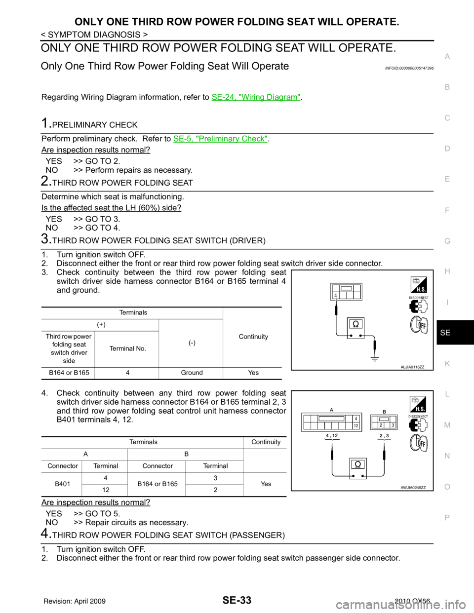
3. Check continuity between the third row power folding seat switch driver side harness connector B164 or B165 terminal 4
and ground.
4. Check continuity between any third row power folding seat switch driver side harness connector B164 or B165 terminal 2, 3
and third row power folding seat control unit harness connector
B401 terminals 4, 12.
Are inspection results normal?
YES >> GO TO 5.
NO >> Repair circuits as necessary.
4.THIRD ROW POWER FOLDING SEAT SWITCH (PASSENGER)
1. Turn ignition switch OFF.
2. Disconnect either the front or rear third row power folding seat switch passenger side connector.
Te r m i n a l s
Continuity
(+)
(-)
Third row power
folding seat
switch driver side Te r m i n a l N o .
B164 or B165 4Ground Yes
ALJIA0116ZZ
Terminals Continuity
AB
Connector Terminal Connector Terminal
B401 4
B164 or B165 3
Ye s
12 2
AWJIA0245ZZ
Revision: April 20092010 QX56
Page 3307 of 4210
THIRD ROW POWER FOLDING SEAT WILL OPERATE IN ONLY ONE DIREC-TION.
SE-35
< SYMPTOM DIAGNOSIS >
C
D E
F
G H
I
K L
M A
B
SE
N
O P
THIRD ROW POWER FOLDING SEAT WI LL OPERATE IN ONLY ONE DI-
RECTION.
Third Row Power Folding Seat Will Operate in Only One DirectionINFOID:0000000005147397
Regarding Wiring Diagram information, refer to SE-24, "Wiring Diagram".
1.PRELIMINARY CHECK
Perform preliminary check. Refer to SE-5, "
Preliminary Check".
Are inspection results normal?
YES >> GO TO 2.
NO >> Perform repairs as necessary.
2.THIRD ROW POWER FOLDING SEAT
Determine which seat is malfunctioning.
Is the affected seat the LH (60%) side?
YES >> GO TO 3.
NO >> GO TO 4.
3.THIRD ROW POWER FOLDING SEAT SWITCH (DRIVER)
1. Turn ignition switch OFF.
2. Disconnect any third row power folding seat switch driver side connector.
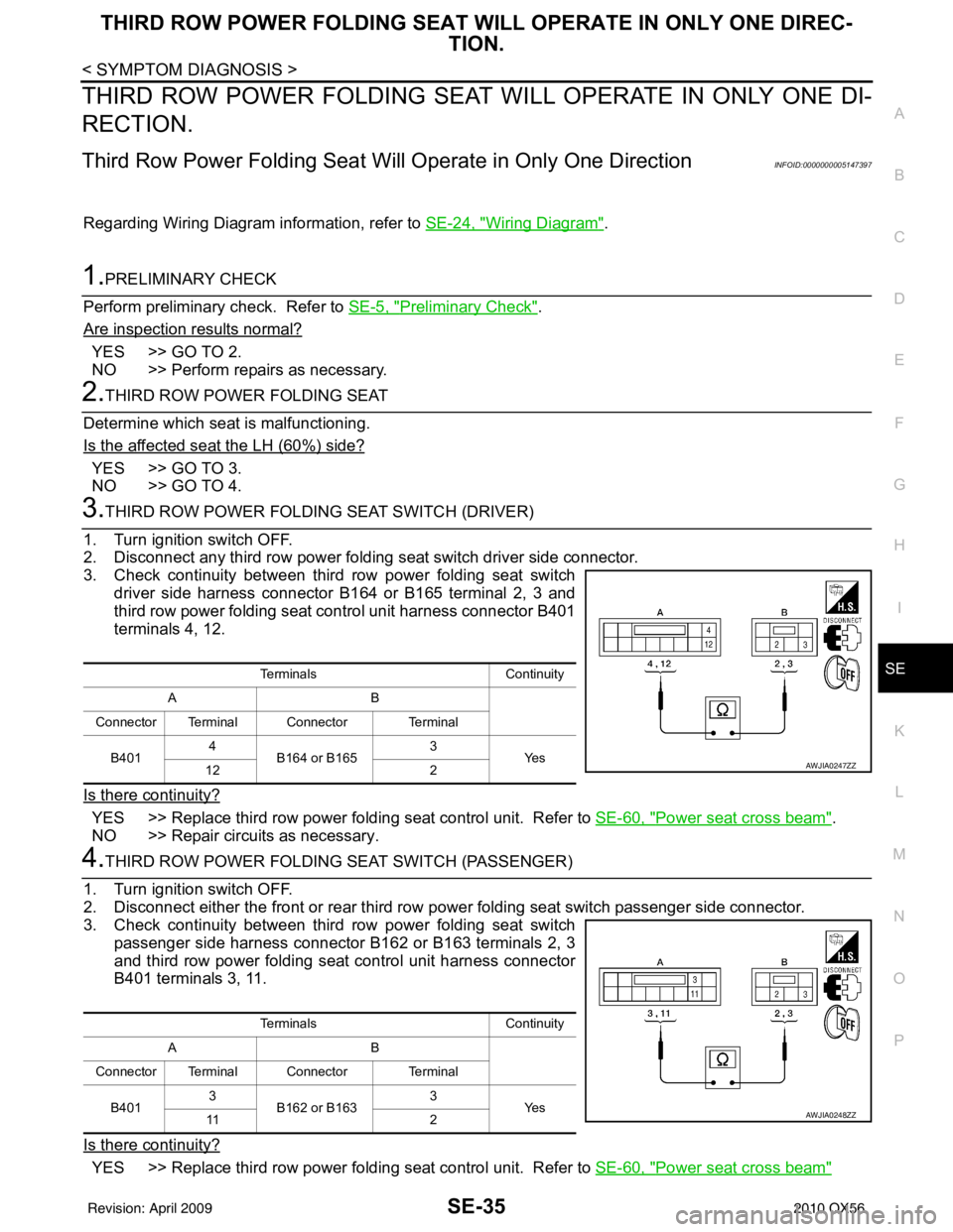
3. Check continuity between third row power folding seat switch driver side harness connector B164 or B165 terminal 2, 3 and
third row power folding seat control unit harness connector B401
terminals 4, 12.
Is there continuity?
YES >> Replace third row power folding seat control unit. Refer to SE-60, "Power seat cross beam".
NO >> Repair circuits as necessary.
4.THIRD ROW POWER FOLDING SEAT SWITCH (PASSENGER)
1. Turn ignition switch OFF.
2. Disconnect either the front or rear third row power folding seat switch passenger side connector.
3. Check continuity between third row power folding seat switch passenger side harness connector B162 or B163 terminals 2, 3
and third row power folding seat control unit harness connector
B401 terminals 3, 11.
Is there continuity?
YES >> Replace third row power folding seat control unit. Refer to SE-60, "Power seat cross beam"
TerminalsContinuity
AB
Connector Terminal Connector Terminal
B401 4
B164 or B165 3
Ye s
12 2
AWJIA0247ZZ
Terminals Continuity
AB
Connector Terminal Connector Terminal
B401 3
B162 or B163 3
Ye s
11 2
AWJIA0248ZZ
Revision: April 20092010 QX56
Page 3309 of 4210

THIRD ROW POWER FOLDING SEAT WILL STOP SHORT OF IT’S FULLY UP
OR DOWN POSITION.
SE-37
< SYMPTOM DIAGNOSIS >
C
DE
F
G H
I
K L
M A
B
SE
N
O P
THIRD ROW POWER FOLDING SEAT WI LL STOP SHORT OF IT’S FULLY
UP OR DOWN POSITION.
Third Row Power Folding Seat Stops Short of it's Fully Up or Down Position
INFOID:0000000005147398
Regarding Wiring Diagram information, refer to SE-24, "Wiring Diagram".
1.PRELIMINARY CHECK
Perform preliminary check. Refer to SE-5, "
Preliminary Check".
Are inspection results normal?
YES >> GO TO 2.
NO >> Perform repairs as necessary.
2.CHECK HISTORY
Check to see if a previous normal seat foldi ng operation was interrupted due to low voltage condition.
Was voltage interrupted?
YES >> Perform learn procedure by operating affected seat until seat reaches full open/closed position.
NO >> GO TO 3.
3.THIRD ROW POWER FOLDING SEAT MOTOR
1. Turn ignition switch OFF.
2. Disconnect third row power folding seat motor harness connec- tor and third row power folding seat control unit harness connec-
tor.
3. Check continuity between third row power folding seat motor
harness connector B403 (LH) or B426 (RH) terminals 1, 2 and
third row power folding seat control unit harness connector ter-
minals 10, 15 (LH) or 9, 15 (RH).
Is there continuity?
YES >> Replace affected third row power folding seat motor. Refer to SE-57, "Exploded View".
NO >> Repair circuits as necessary.
Te r m i n a l s Continuity
Connector Terminal Connector Terminal
A: B401 9 (RH)
C: B426 (RH)
1
Ye s
10 (LH)
C: B403 (LH)
B: B402 15 (LH/RH) C: B426 (RH)
2
C: B403 (LH)
AWJIA0362ZZ
Revision: April 20092010 QX56
Page 3352 of 4210
SEC-1
BODY EXTERIOR, DOORS, ROOF & VEHICLE SECURITY
C
DE
F
G H
I
J
L
M
SECTION SEC
A
B
SEC
N
O P
CONTENTS
SECURITY CONTROL SYSTEM
WITH INTELLIGENT KEY SYSTEM
BASIC INSPECTION ....... .............................
4
DIAGNOSIS AND REPAIR WORKFLOW ..... .....4
Work Flow ........................................................... ......4
PRE-INSPECTION FOR DIAGNOSTIC ..............7
Basic Inspection .................................................. ......7
Vehicle Security Operation Check ............................7
INSPECTION AND ADJUSTMENT .....................9
ADDITIONAL SERVICE WHEN REPLACING
CONTROL UNIT .................................................... ......
9
ADDITIONAL SERVICE WHEN REPLACING
CONTROL UNIT : Special Repair Requirement .......
9
ECM RE-COMMUNICATING FUNCTION ............. ......9
ECM RE-COMMUNICATING FUNCTION : De-
scription .....................................................................
9
ECM RE-COMMUNICATING FUNCTION : Spe-
cial Repair Requirement ............................................
9
FUNCTION DIAGNOSIS ..............................10
INTELLIGENT KEY SYSTEM/ENGINE
START FUNCTIO N ........................................ ....
10
System Diagram .................................................. ....10
System Description .................................................10
Component Parts Location ......................................12
Component Description ...........................................13
INFINITI VEHICLE IMMOBILIZER SYSTEM-
NATS ..................................................................
14
System Diagram .................................................. ....14
System Description .................................................14
Component Parts Location ......................................16
Component Description ..........................................16
VEHICLE SECURITY SYSTEM .........................18
System Diagram .................................................. ....18
System Description .................................................18
Component Parts Location .................................. ....19
Component Description ...........................................20
DIAGNOSIS SYSTEM (BCM) ...........................21
COMMON ITEM ..................................................... ....21
COMMON ITEM : CONSULT-III Function (BCM -
COMMON ITEM) .....................................................
21
IMMU ...................................................................... ....21
IMMU : CONSULT-III Function (BCM - IMMU) ........22
THEFT ALM ........................................................... ....22
THEFT ALM : CONSULT-III Function (BCM -
THEFT ALM) ....................................................... ....
22
DIAGNOSIS SYSTEM (INTELLIGENT KEY
UNIT) .................................................................
24
CONSULT-III Function (INTELLIGENT KEY) ..........24
COMPONENT DIAGNOSIS .........................26
U1000 CAN COMM CIRCUIT ...........................26
Description ........................................................... ....26
DTC Logic ................................................................26
Diagnosis Procedure ...............................................26
U1010 CONTROL UNIT (CAN) .........................27
Description ...............................................................27
DTC Logic ................................................................27
Diagnosis Procedure ...............................................27
Special Repair Requirement ....................................27
B2013 ID DISCORD I-KEY-STRG ....................28
Description ...............................................................28
DTC Logic ................................................................28
Diagnosis Procedure ...............................................28
B2190 NATS ANTENNA AMP. .........................31
Description ...............................................................31
DTC Logic ................................................................31
Diagnosis Procedure ...............................................31
Revision: April 20092010 QX56
Page 3353 of 4210

SEC-2
B2191 DIFFERENCE OF KEY ..........................34
Description ........................................................... ...34
DTC Logic ...............................................................34
Diagnosis Procedure ..............................................34
B2192 ID DISCORD, IMMU-ECM ......................35
Description ........................................................... ...35
DTC Logic ...............................................................35
Diagnosis Procedure ..............................................35
B2193 CHAIN OF ECM-IMMU ...........................37
Description ........................................................... ...37
DTC Logic ...............................................................37
Diagnosis Procedure ..............................................37
B2194 ID DISCORD IMMU-I-KEY .....................38
Description ........................................................... ...38
DTC Logic ...............................................................38
Diagnosis Procedure ..............................................38
B2552 INTELLIGENT KEY ................................39
Description ........................................................... ...39
DTC Logic ...............................................................39
Diagnosis Procedure ..............................................39
Special Repair Requirement ...................................39
B2590 ID DISCORD BCM-I-KEY .................... ...40
Description ........................................................... ...40
DTC Logic ...............................................................40
Diagnosis Procedure ..............................................40
P1610 LOCK MODE ..........................................41
Description ........................................................... ...41
DTC Logic ...............................................................41
Diagnosis Procedure ..............................................41
P1611 ID DISCORD, IMMU-ECM ......................42
Description ........................................................... ...42
DTC Logic ...............................................................42
Diagnosis Procedure ..............................................42
P1612 CHAIN OF ECM-IMMU ...........................44
Description ........................................................... ...44
DTC Logic ...............................................................44
Diagnosis Procedure ..............................................44
P1614 CHAIN OF IMMU-KEY ...........................45
Description ........................................................... ...45
DTC Logic ...............................................................45
Diagnosis Procedure ..............................................45
P1615 DIFFRENCE OF KEY .............................48
Description ........................................................... ...48
DTC Logic ...............................................................48
Diagnosis Procedure ..............................................48
POWER SUPPLY AND GROUND CIRCUIT .....49
INTELLIGENT KEY UNIT ...................................... ...49
INTELLIGENT KEY UNIT : Diagnosis Procedure ...49
BCM ........................................................................ ...49
BCM : Diagnosis Procedure ....................................49
KEY CYLINDER SWITCH .................................51
Description ..............................................................51
Component Function Check ...................................51
Diagnosis Procedure ...............................................51
IGNITION KNOB SWITCH ................................53
Ignition Knob Switch Check ................................. ...53
HOOD SWITCH .................................................55
Diagnosis Procedure ............................................ ...55
HORN FUNCTION .............................................57
Symptom Table .................................................... ...57
VEHICLE SECURITY INDICATOR ...................58
Description ........................................................... ...58
Component Function Check ..................................58
Diagnosis Procedure ...............................................58
ECU DIAGNOSIS .......................................60
BCM (BODY CONTROL MODULE) ............... ...60
Reference Value .................................................. ...60
Terminal Layout ......................................................63
Physical Values .......................................................63
Wiring Diagram - VEHICLE SECURITY SYSTEM ...69
Wiring Diagram - IVIS .............................................80
Fail Safe .................................................................87
DTC Inspection Priority Chart ...............................88
DTC Index ..............................................................88
INTELLIGENT KEY UNIT ..................................90
Reference Value - Intelligent Key Unit ................. ...90
Reference Value - Steering Lock Solenoid .............93
Wiring Diagram - INTELLIGENT KEY SYSTEM/
ENGINE START FUNCTION - ................................
94
Fail Safe ...............................................................104
DTC Inspection Priority Chart .............................105
DTC Index ............................................................105
IPDM E/R (INTELLIGENT POWER DISTRI-
BUTION MODULE ENGINE ROOM) ................
106
Reference Value .................................................. .106
Terminal Layout ....................................................108
Physical Values .....................................................109
Fail Safe ...............................................................113
DTC Index ............................................................114
SYMPTOM DIAGNOSIS ...........................115
INTELLIGENT KEY SYSTEM/ENGINE
START FUNCTION SYMPTOMS ................... ..
115
Symptom Table .................................................... .115
VEHICLE SECURITY SYSTEM SYMPTOMS ..116
Symptom Table .....................................................116
INFINITI VEHICLE IMMOBILIZER SYSTEM-
NATS SYMPTOMS ...........................................
117
Symptom Table .................................................... .117
Revision: April 20092010 QX56
Page 3361 of 4210
![INFINITI QX56 2010 Factory Service Manual SEC-10
< FUNCTION DIAGNOSIS >[WITH INTELLIGENT KEY SYSTEM]
INTELLIGENT KEY SYSTEM/ENGINE START FUNCTION
FUNCTION DIAGNOSIS
INTELLIGENT KEY SYSTEM
/ENGINE START FUNCTION
System DiagramINFOID:0000000005 INFINITI QX56 2010 Factory Service Manual SEC-10
< FUNCTION DIAGNOSIS >[WITH INTELLIGENT KEY SYSTEM]
INTELLIGENT KEY SYSTEM/ENGINE START FUNCTION
FUNCTION DIAGNOSIS
INTELLIGENT KEY SYSTEM
/ENGINE START FUNCTION
System DiagramINFOID:0000000005](/manual-img/42/57032/w960_57032-3360.png)
SEC-10
< FUNCTION DIAGNOSIS >[WITH INTELLIGENT KEY SYSTEM]
INTELLIGENT KEY SYSTEM/ENGINE START FUNCTION
FUNCTION DIAGNOSIS
INTELLIGENT KEY SYSTEM
/ENGINE START FUNCTION
System DiagramINFOID:0000000005147067
System DescriptionINFOID:0000000005147068
INPUT/OUTPUT SIGNAL CHART
Intelligent Key Unit
IPDM E/R
BCM
SYSTEM DESCRIPTION
• The engine start function of Intelligent Key system is a system that makes it possible to start and stop the
engine without using the key. It verifies the electroni c ID using two-way communications when pressing the
ignition knob switch while carrying the Intelligent Key, which operates based on the results of electronic ID
verification for Intelligent Key using two-way communications between the Intelligent Key and the vehicle.
NOTE:
The driver should carry the Intelligent Key at all times.
Switch/Input signal Input signal to
Intelligent Key unit Intelligent Key unit
function Actuator/Output signal
Key switch Mechanical key
(insert/remove)
Engine start function• KEY warning lamp/buzzer
• Steering lock solenoid
• Starter relay request (to IPDM E/R)
• Inside key antenna
(Front and rear center console, over-
head console, luggage area)
• Key interlock solenoid
Ignition knob switch
Ignition knob
(push/release)
Steering lock solenoid Steering lock
(lock/unlock)
Inside key antenna
(Front and rear center console, over-
head console, luggage area) Intelligent key
(inside antenna detection
area or not.)
Switch/Input signal Input signal to
IPDM E/R IPDM E/R function
Actuator/Output signal
Transmission range switch P, N range Engine start function• Starter relay
• Starter motor
Switch/Input signal Input signal to
BCM BCM function
Actuator/Output signal
Key switch Brake
(press/release)
Engine start function• Inside key antenna
(Front and rear center console, over-
head console, luggage area)
ALKIA0925GB
Revision: April 20092010 QX56