Page 3556 of 4210

SRC-10
< FUNCTION DIAGNOSIS >
OCCUPANT CLASSIFICATION SYSTEM
OCCUPANT CLASSIFICATION SYSTEM
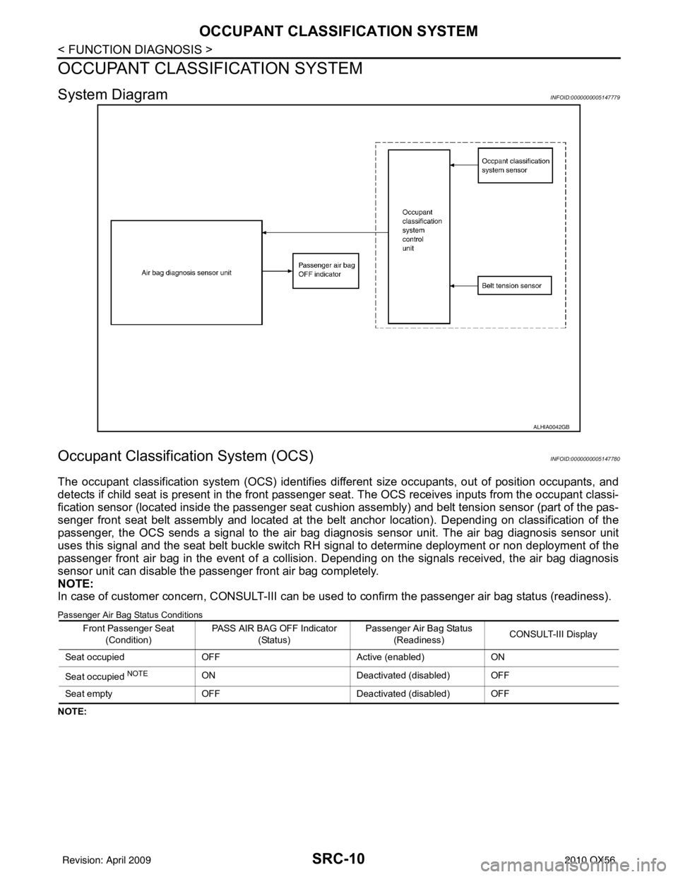
System DiagramINFOID:0000000005147779
Occupant Classification System (OCS)INFOID:0000000005147780
The occupant classification system (OCS) identifies different size occupants, out of position occupants, and
detects if child seat is present in the front passenger seat. The OCS receives inputs from the occupant classi-
fication sensor (located inside the passenger seat cushion assembly) and belt tension sensor (part of the pas-
senger front seat belt assembly and located at the belt anchor location). Depending on classification of the
passenger, the OCS sends a signal to the air bag diagnos is sensor unit. The air bag diagnosis sensor unit
uses this signal and the seat belt buckle switch RH signal to determine deployment or non deployment of the
passenger front air bag in the event of a collision. Depending on the signals received, the air bag diagnosis
sensor unit can disable the passenger front air bag completely.
NOTE:
In case of customer concern, CONSULT-III can be used to confirm the passenger air bag status (readiness).
Passenger Air Bag Status Conditions
NOTE:
ALHIA0042GB
Front Passenger Seat
(Condition) PASS AIR BAG OFF Indicator
(Status) Passenger Air Bag Status
(Readiness) CONSULT-III Display
Seat occupied OFF Active (enabled)ON
Seat occupied
NOTEON Deactivated (disabled) OFF
Seat empty OFF Deactivated (disabled) OFF
Revision: April 20092010 QX56
Page 3558 of 4210
SRC-12
< FUNCTION DIAGNOSIS >
PASSENGER SEAT BELT WARNING SYSTEM
PASSENGER SEAT BELT WARNING SYSTEM
System DiagramINFOID:0000000005147781
System DescriptionINFOID:0000000005147782
The passenger seat belt warning system will remind the driver if the
driver or front passenger seat belt should be buckled by turning on
the seat belt warning light (1). The system works in conjunction with
the occupant classification system. Refer to SRC-10, "
Occupant
Classification System (OCS)".
Passenger Seat Belt Warning System Operation
Component Parts LocationINFOID:0000000005147783
Refer to SRC-7, "SRS Component Parts Location".
ALHIA0028GB
AWHIA0032ZZ
Driver seat status
(Ignition switch ON) Passenger seat status Seat belt buckle switch
LH status Seat belt buckle switch
RH statusSeat belt warning lamp
Seat occupied Seat occupied
Buckled Buckled
Off
Unbuckled On
Seat unoccupied —Off
— Unbuckled On
Revision: April 20092010 QX56
Page 3617 of 4210
DIAGNOSIS SENSOR UNITSRC-71
< ECU DIAGNOSIS >
C
DE
F
G
I
J
K L
M A
B
SRC
N
O P
ECU DIAGNOSIS
DIAGNOSIS SENSOR UNIT
Wiring DiagramINFOID:0000000005147846
ABHWA0067GB
Revision: April 20092010 QX56
Page 3639 of 4210

ST-1
STEERING
C
DE
F
H I
J
K L
M
SECTION ST
A
B
ST
N
O P
CONTENTS
STEERING SYSTEM
PRECAUTION ....... ........................................3
PRECAUTIONS .............................................. .....3
Precaution for Supplemental Restraint System
(SRS) "AIR BAG" and "SEAT BELT PRE-TEN-
SIONER" ............................................................. ......
3
Precaution Necessary for Steering Wheel Rota-
tion After Battery Disconnect ............................... ......
3
PREPARATION ............................................5
PREPARATION .............................................. .....5
Special Service Tool ........................................... ......5
Commercial Service Tool ..........................................6
FUNCTION DIAGNOSIS ...............................7
HEATED STEERING WHEEL ........................ .....7
System Diagram .................................................. ......7
System Description ...................................................7
Component Parts Location ........................................7
Component Description .............................................8
COMPONENT DIAGNOSIS ..........................9
HEATED STEERING WHEEL ........................ .....9
Wiring Diagram ................................................... ......9
SYMPTOM DIAGNOSIS ..............................12
NOISE, VIBRATION AND HARSHNESS
(NVH) TROUBLESHOOTING ........................ ....
12
NVH Troubleshooting Chart ................................ ....12
ON-VEHICLE MAINTENANCE ....................13
POWER STEERING FLUID ........................... ....13
Checking Fluid Level ........................................... ....13
Checking Fluid Leakage ..........................................13
Air Bleeding Hydraulic System ................................13
ON-VEHICLE REPAIR .................................15
STEERING WHEEL ..........................................15
On-Vehicle Inspection and Service ..................... ....15
POWER STEERING OIL PUMP .......................17
On-Vehicle Inspection and Service .........................17
REMOVAL AND INSTALLATION ...............18
STEERING WHEEL ..........................................18
Removal and Installation ..................................... ....18
TILT SYSTEM ...................................................19
Removal and Installation .........................................19
STEERING COLUMN ........................................20
Removal and Installation .........................................20
POWER STEERING GEAR AND LINKAGE ....23
Removal and Installation .........................................23
POWER STEERING OIL PUMP .......................26
Removal and Installation .........................................26
HYDRAULIC LINE ............................................27
Removal and Installation .........................................27
DISASSEMBLY AND ASSEMBLY ..............29
STEERING COLUMN ........................................29
Disassembly and Assembly ................................. ....29
POWER STEERING GEAR AND LINKAGE ....31
Disassembly and Assembly .....................................31
POWER STEERING OIL PUMP .......................34
Disassembly and Assembly .....................................34
SERVICE DATA AND SPECIFICATIONS
(SDS) ............... .......................................... ...
35
SERVICE DATA AND SPECIFICATIONS
(SDS) .................................................................
35
Steering Wheel .................................................... ....35
Revision: April 20092010 QX56
Page 3645 of 4210

HEATED STEERING WHEELST-7
< FUNCTION DIAGNOSIS >
C
DE
F
H I
J
K L
M A
B
ST
N
O P
FUNCTION DIAGNOSIS
HEATED STEERING WHEEL
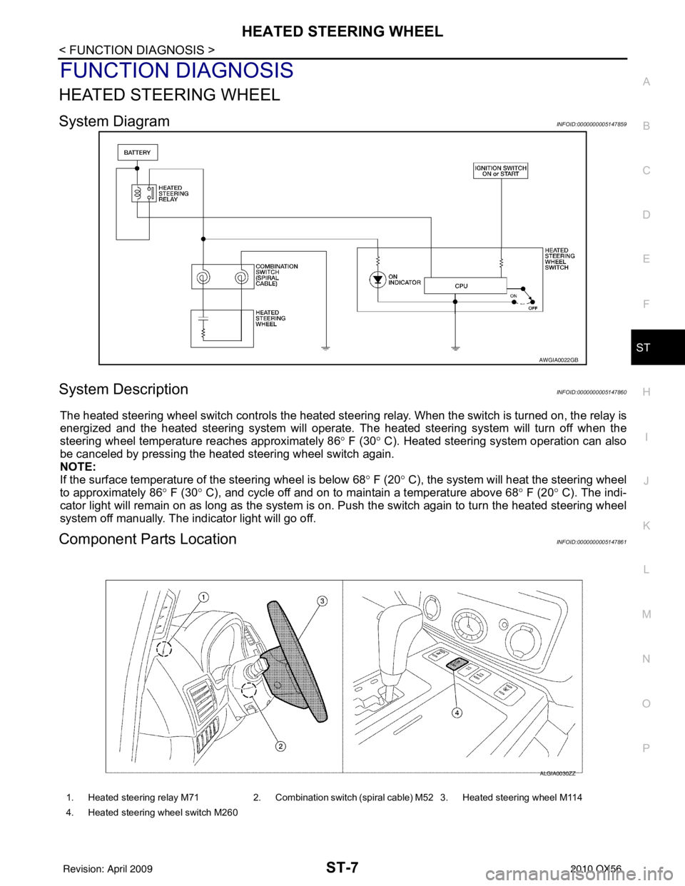
System DiagramINFOID:0000000005147859
System DescriptionINFOID:0000000005147860
The heated steering wheel switch controls the heated steeri ng relay. When the switch is turned on, the relay is
energized and the heated steering system will operate. T he heated steering system will turn off when the
steering wheel temperature reaches approximately 86 ° F (30 ° C). Heated steering system operation can also
be canceled by pressing the heated steering wheel switch again.
NOTE:
If the surface temperature of the steering wheel is below 68 ° F (20 ° C), the system will heat the steering wheel
to approximately 86 ° F (30 ° C), and cycle off and on to maintain a temperature above 68 ° F (20 ° C). The indi-
cator light will remain on as long as the system is on. Push the switch again to turn the heated steering wheel
system off manually. The indicator light will go off.
Component Parts LocationINFOID:0000000005147861
AWGIA0022GB
1. Heated steering relay M71 2. Combination switch (spiral cable) M52 3. Heated steering wheel M114
4. Heated steering wheel switch M260
ALGIA0030ZZ
Revision: April 20092010 QX56
Page 3647 of 4210
HEATED STEERING WHEELST-9
< COMPONENT DIAGNOSIS >
C
DE
F
H I
J
K L
M A
B
ST
N
O P
COMPONENT DIAGNOSIS
HEATED STEERING WHEEL
Wiring DiagramINFOID:0000000005147863
ABGWA0009GB
Revision: April 20092010 QX56
Page 3676 of 4210

STR-1
ENGINE
C
DE
F
G H
I
J
K L
M
SECTION STR
A
STR
N
O P
CONTENTS
STARTING SYSTEM
PRECAUTION ....... ........................................2
PRECAUTIONS .............................................. .....2
Precaution for Supplemental Restraint System
(SRS) "AIR BAG" and "SEAT BELT PRE-TEN-
SIONER" ............................................................. ......
2
Precaution Necessary for Steering Wheel Rota-
tion After Battery Disconnect ............................... ......
2
Precaution for Power Generation Variable Voltage
Control System ..........................................................
3
PREPARATION ............................................4
PREPARATION .............................................. .....4
Special Service Tool ........................................... ......4
Commercial Service Tool ..........................................4
BASIC INSPECTION ....................................5
DIAGNOSIS AND REPAIR WORKFLOW ..... .....5
Work Flow ........................................................... ......5
FUNCTION DIAGNOSIS ...............................8
STARTING SYSTEM ...................................... .....8
System Diagram .................................................. ......8
System Description ...................................................8
Component Parts Location ........................................8
Component Description ............................................9
COMPONENT DIAGNOSIS .........................10
B TERMINAL CIRCUIT .....................................10
Description ........................................................... ....10
Diagnosis Procedure ...............................................10
S CONNECTOR CIRCUIT .................................12
Description ...............................................................12
Diagnosis Procedure ...............................................12
STARTING SYSTEM .........................................14
Wiring Diagram .................................................... ....14
SYMPTOM DIAGNOSIS ..............................18
STARTING SYSTEM .........................................18
Symptom Table ................................................... ....18
ON-VEHICLE REPAIR .................................19
STARTER MOTOR ...........................................19
Removal and Installation ..................................... ....19
SERVICE DATA AND SPECIFICATIONS
(SDS) ............... .......................................... ...
20
STARTER MOTOR ...........................................20
Starter .................................................................. ....20
Revision: April 20092010 QX56
Page 3683 of 4210
STR-8
< FUNCTION DIAGNOSIS >
STARTING SYSTEM
FUNCTION DIAGNOSIS
STARTING SYSTEM
System DiagramINFOID:0000000005149550
System DescriptionINFOID:0000000005149551
The starter motor plunger closes and provides a closed circuit between the battery and the starter motor. The
starter motor is grounded to the cylinder block. With power and ground supplied, the starter motor operates.
Component Parts LocationINFOID:0000000005149552
ALBIA0416GB
1. A/T assembly F9 (with built in TCM
F502) 2. IPDM E/R E119, E120, E122, E124 3. BCM M18 (view with instrument panel
lower LH panel removed)
AWBIA0127ZZ
Revision: April 20092010 QX56