Page 4014 of 4210

WCS
POWER SUPPLY AND GROUND CIRCUITWCS-15
< COMPONENT DIAGNOSIS >
C
DE
F
G H
I
J
K L
M B A
O P
COMPONENT DIAGNOSIS
POWER SUPPLY AND GROUND CIRCUIT
COMBINATION METER
COMBINATION METER : Diagnosis ProcedureINFOID:0000000005382371
Regarding Wiring Diagram information, refer to WCS-30, "Wiring Diagram".
1.CHECK FUSES
Check for blown combination meter fuses.
Is the inspection result normal?
YES >> GO TO 2
NO >> If fuse is blown, be sure to eliminate cause of malfunction before installing new fuse.
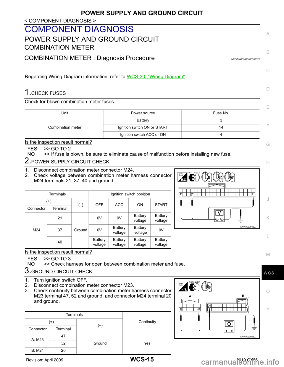
2.POWER SUPPLY CIRCUIT CHECK
1. Disconnect combination meter connector M24.
2. Check voltage between combination meter harness connector M24 terminals 21, 37, 40 and ground.
Is the inspection result normal?
YES >> GO TO 3
NO >> Check harness for open between combination meter and fuse.
3.GROUND CIRCUIT CHECK
1. Turn ignition switch OFF.
2. Disconnect combination meter connector M23.
3. Check continuity between combination meter harness connector M23 terminal 47, 52 and ground, and connector M24 terminal 20
and ground.
Unit Power source Fuse No.
Combination meter Battery 3
Ignition switch ON or START 14
Ignition switch ACC or ON 4
TerminalsIgnition switch position
(+) (–) OFF ACC ON START
Connector Terminal
M24 21
Ground 0V 0V
Battery
voltage Battery
voltage
37 0VBattery
voltage Battery
voltage 0V
40 Battery
voltage Battery
voltage Battery
voltage Battery
voltage
AWNIA0204ZZ
Te r m i n a l s
Continuity
(+)
(–)
Connector Terminal
A: M23 47
Ground Yes
52
B: M24 20
AWNIA0205ZZ
Revision: April 20092010 QX56
Page 4015 of 4210

WCS-16
< COMPONENT DIAGNOSIS >
POWER SUPPLY AND GROUND CIRCUIT
Is the inspection result normal?
YES >> Inspection End.
NO >> Check ground harness.
BCM (BODY CONTROL MODULE)
BCM (BODY CONTROL MODULE) : Diagnosis ProcedureINFOID:0000000005382372
Regarding Wiring Diagram information, refer to WCS-59, "Wiring Diagram".
1. CHECK FUSES AND FUSIBLE LINK
Check that the following fuses and fusible link are not blown.
Is the fuse blown?
YES >> Replace the blown fuse or fusible link after repairing the affected circuit.
NO >> GO TO 2
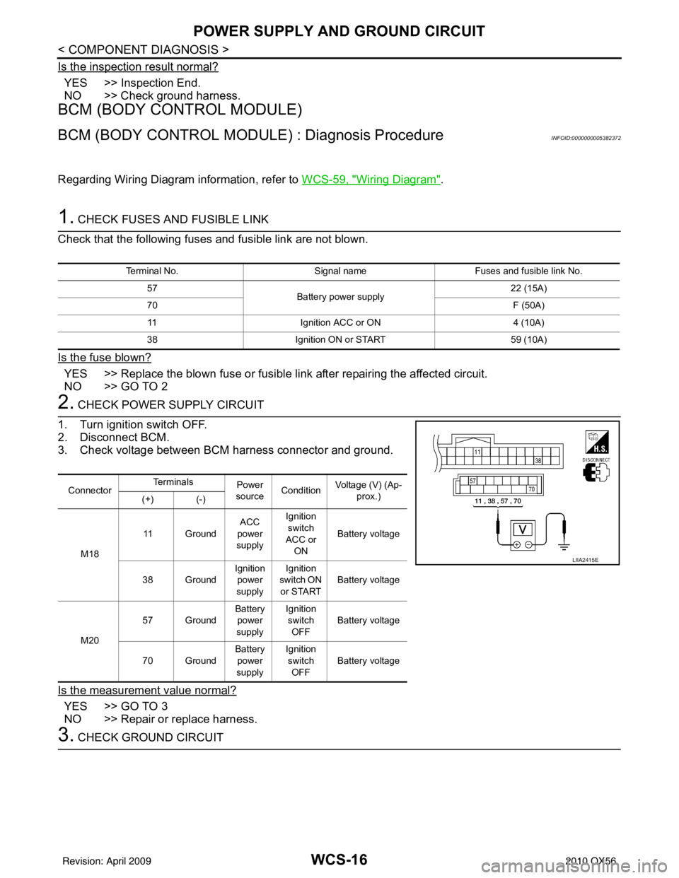
2. CHECK POWER SUPPLY CIRCUIT
1. Turn ignition switch OFF.
2. Disconnect BCM.
3. Check voltage between BCM harness connector and ground.
Is the measurement value normal?
YES >> GO TO 3
NO >> Repair or replace harness.
3. CHECK GROUND CIRCUIT
Terminal No. Signal nameFuses and fusible link No.
57 Battery power supply 22 (15A)
70 F (50A)
11 Ignition ACC or ON 4 (10A)
38 Ignition ON or START 59 (10A)
ConnectorTe r m i n a l s
Power
source Condition
Voltage (V) (Ap-
prox.)
(+) (-)
M18 11 Ground
ACC
power
supply Ignition
switch
ACC or ON Battery voltage
38 Ground Ignition
power
supply Ignition
switch ON or START Battery voltage
M20 57 Ground
Battery
power
supply Ignition
switch
OFF Battery voltage
70 Ground Battery
power
supply Ignition
switch OFF Battery voltage
LIIA2415E
Revision: April 20092010 QX56
Page 4018 of 4210

WCS
SEAT BELT BUCKLE SWITCH SIGNAL CIRCUIT
WCS-19
< COMPONENT DIAGNOSIS >
C
D E
F
G H
I
J
K L
M B A
O P
SEAT BELT BUCKLE SW ITCH SIGNAL CIRCUIT
DescriptionINFOID:0000000005146158
Transmits a seat belt buckle switch signal to the combination meter.
Component Function CheckINFOID:0000000005146159
1.CHECK COMBINATION METER INPUT SIGNAL
Select “DATA MONITOR” for “METER/M&A” and check the “SEAT BELT W/L” monitor value.
>> Inspection End.
Diagnosis ProcedureINFOID:0000000005146160
Regarding Wiring Diagram information, refer to WCS-23, "Wiring Diagram".
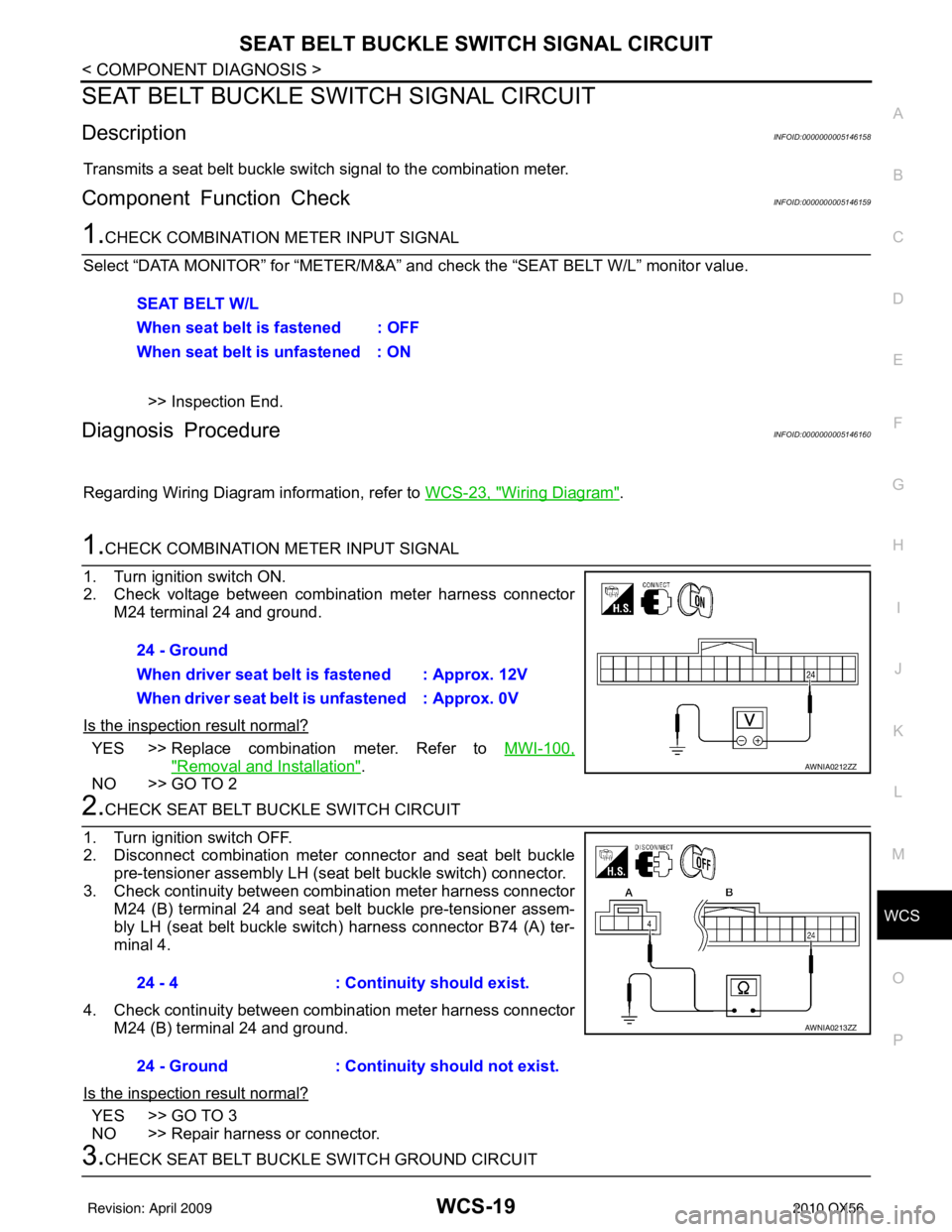
1.CHECK COMBINATION METER INPUT SIGNAL
1. Turn ignition switch ON.
2. Check voltage between combination meter harness connector M24 terminal 24 and ground.
Is the inspection result normal?
YES >> Replace combination meter. Refer to MWI-100,
"Removal and Installation".
NO >> GO TO 2
2.CHECK SEAT BELT BUCKLE SWITCH CIRCUIT
1. Turn ignition switch OFF.
2. Disconnect combination meter connector and seat belt buckle pre-tensioner assembly LH (seat belt buckle switch) connector.
3. Check continuity between combination meter harness connector M24 (B) terminal 24 and seat belt buckle pre-tensioner assem-
bly LH (seat belt buckle switch ) harness connector B74 (A) ter-
minal 4.
4. Check continuity between combination meter harness connector M24 (B) terminal 24 and ground.
Is the inspection result normal?
YES >> GO TO 3
NO >> Repair harness or connector.
3.CHECK SEAT BELT BUCKLE SWITCH GROUND CIRCUIT SEAT BELT W/L
When seat belt is fastened : OFF
When seat belt is unfastened : ON
24 - Ground
When driver seat belt is fastened : Approx. 12V
When driver seat belt is unfastened : Approx. 0V
AWNIA0212ZZ
24 - 4
: Continuity should exist.
24 - Ground : Continuity should not exist.
AWNIA0213ZZ
Revision: April 20092010 QX56
Page 4020 of 4210

WCS
KEY SWITCH SIGNAL CIRCUITWCS-21
< COMPONENT DIAGNOSIS >
C
DE
F
G H
I
J
K L
M B A
O P
KEY SWITCH SIGNAL CIRCUIT
DescriptionINFOID:0000000005146162
Transmits a key switch signal to the BCM.
Component Function CheckINFOID:0000000005146163
1.CHECK BCM INPUT SIGNAL
Select “DATA MONITOR” for “BCM” and c heck the “KEY ON SW” monitor value.
>> Inspection End.
Diagnosis ProcedureINFOID:0000000005146164
Regarding Wiring Diagram information, refer to WCS-23, "Wiring Diagram".
1.CHECK FUSE
Check if the key switch and ignition knob switch 10A fuse (No. 62, located in the fuse and relay box) is blown.
Is the fuse blown?
YES >> Be sure to repair the cause of malfunction before installing new fuse.
NO >> GO TO 2
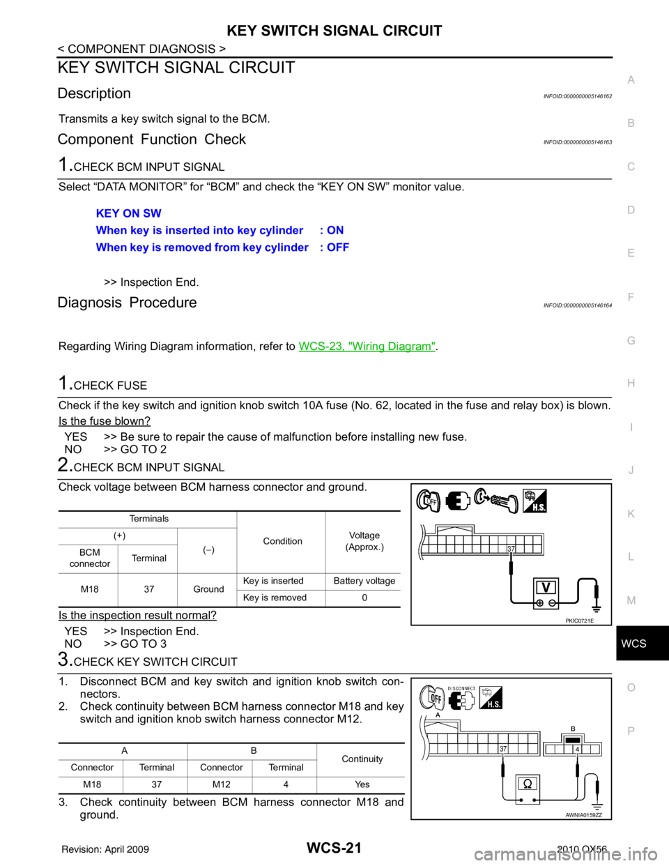
2.CHECK BCM INPUT SIGNAL
Check voltage between BCM harness connector and ground.
Is the inspection result normal?
YES >> Inspection End.
NO >> GO TO 3
3.CHECK KEY SWITCH CIRCUIT
1. Disconnect BCM and key switch and ignition knob switch con- nectors.
2. Check continuity between BCM harness connector M18 and key
switch and ignition knob switch harness connector M12.
3. Check continuity between BCM harness connector M18 and ground.KEY ON SW
When key is inserted into key cylinder : ON
When key is removed from key cylinder : OFF
Te r m i n a l s
ConditionVo l ta g e
(Approx.)
(+)
(−)
BCM
connector Te r m i n a l
M18 37 Ground Key is inserted Battery voltage
Key is removed 0
PKIC0721E
AB
Continuity
Connector Terminal Connector Terminal
M18 37M12 4 Yes
AWNIA0159ZZ
Revision: April 20092010 QX56
Page 4022 of 4210
WCS
WARNING CHIME SYSTEMWCS-23
< COMPONENT DIAGNOSIS >
C
DE
F
G H
I
J
K L
M B A
O P
WARNING CHIME SYSTEM
Wiring DiagramINFOID:0000000005146166
ABNWA0418GB
Revision: April 20092010 QX56
Page 4029 of 4210
WCS-30
< ECU DIAGNOSIS >
COMBINATION METER
Wiring Diagram
INFOID:0000000005382409
ABNWA0408GB
Revision: April 20092010 QX56
Page 4058 of 4210
WCS
BCM (BODY CONTROL MODULE)WCS-59
< ECU DIAGNOSIS >
C
DE
F
G H
I
J
K L
M B A
O P
Wiring DiagramINFOID:0000000005382426
ABMWA0374GB
Revision: April 20092010 QX56
Page 4070 of 4210

WT-1
SUSPENSION
C
DF
G H
I
J
K L
M
SECTION WT
A
B
WT
N
O PCONTENTS
ROAD WHEELS & TIRES
BASIC INSPECTION ....... .............................3
DIAGNOSIS AND REPAIR WORKFLOW ..... .....3
Repair Work Flow ................................................ ......3
INSPECTION AND ADJUSTMENT .....................5
Preliminary Check ............................................... ......5
Transmitter Wake Up Operation ...............................5
ID Registration Procedure .........................................6
FUNCTION DIAGNOSIS ...............................8
TPMS .............................................................. .....8
System Diagram .................................................. ......8
System Description ...................................................8
System Component .................................................10
DIAGNOSIS SYSTEM (BCM) ............................11
CONSULT-III Function (BCM) ............................. ....11
Self-Diagnosis (Without CONSULT-III) ...................12
COMPONENT DIAGNOSIS .........................14
C1708 - C1711 DATA FROM TRANSMITTER
NOT BEING RECEIVED ................................. ....
14
Description .......................................................... ....14
DTC Logic ...............................................................14
Diagnosis Procedure ...............................................14
Special Repair Requirement ...................................15
C1712 - C1715, C1720 - C1723, C1724 -
C1727 TRANSMITTER MALFUNCTION ....... ....
16
Description .......................................................... ....16
DTC Logic ...............................................................16
Diagnosis Procedure ...............................................16
Special Repair Requirement ...................................17
C1716 - C1719 TRANSMITTER PRESSURE
MALFUNCTION .............................................. ....
18
Description .......................................................... ....18
DTC Logic ...............................................................18
Diagnosis Procedure ...............................................18
Special Repair Requirement ................................ ....18
C1729 VEHICLE SPEED SIGNAL ....................19
Description ...............................................................19
DTC Logic ................................................................19
Diagnosis Procedure ...............................................19
Special Repair Requirement ....................................19
C1735 IGNITION SIGNAL .................................20
Description ...............................................................20
DTC Logic ................................................................20
Diagnosis Procedure ...............................................20
Special Repair Requirement ....................................20
ECU DIAGNOSIS .........................................21
BCM (BODY CONTROL MODULE) .................21
Reference Value .................................................. ....21
Terminal Layout .......................................................24
Physical Values ................................................... ....24
Wiring Diagram - TIRE PRESSURE MONITOR-
ING SYSTEM - ........................................................
30
Self-Diagnosis (With CONSULT-III) .................... ....33
Self-Diagnosis (Without CONSULT-III) ...................34
SYMPTOM DIAGNOSIS ..............................36
TPMS .................................................................36
Symptom Table ................................................... ....36
LOW TIRE PRESSURE WARNING LAMP
DOES NOT TURN ON .......................................
37
Low Tire Pressure Warning Lamp Does Not Come
On When Ignition Switch Is Turned On ...................
37
LOW TIRE PRESSURE WARNING LAMP
STAYS ON ........................................................
38
Low Tire Pressure Warning Lamp Stays On When
Ignition Switch Is Turned On ............................... ....
38
LOW TIRE PRESSURE WARNING LAMP
BLINKS .............................................................
39
Revision: April 20092010 QX56