Page 3106 of 4210
PWO
PWO-1
ELECTRICAL & POWER CONTROL
C
DE
F
G H
I
J
K L
B
SECTION PWO
A
O P
N
CONTENTS
POWER OUTLET
PRECAUTION .......
........................................2
PRECAUTIONS .............................................. .....2
Precaution for Supplemental Restraint System
(SRS) "AIR BAG" and "SEAT BELT PRE-TEN-
SIONER" ............................................................. ......
2
Precaution Necessary for Steering Wheel Rota-
tion After Battery Disconnect ............................... ......
2
COMPONENT DIAGNOSIS ..........................4
POWER SOCKET ..............................................4
Wiring Diagram .................................................... .....4
ON-VEHICLE REPAIR ..................................7
POWER SOCKET ..............................................7
Removal and Installation ..................................... .....7
Revision: April 20092010 QX56
Page 3109 of 4210
PWO-4
< COMPONENT DIAGNOSIS >
POWER SOCKET
COMPONENT DIAGNOSIS
POWER SOCKET
Wiring DiagramINFOID:0000000005146377
ABMWA0422GB
Revision: April 20092010 QX56
Page 3129 of 4210
RF-1
BODY EXTERIOR, DOORS, ROOF & VEHICLE SECURITY
C
DE
F
G H
I
J
L
M
SECTION RF
A
B
RF
N
O P
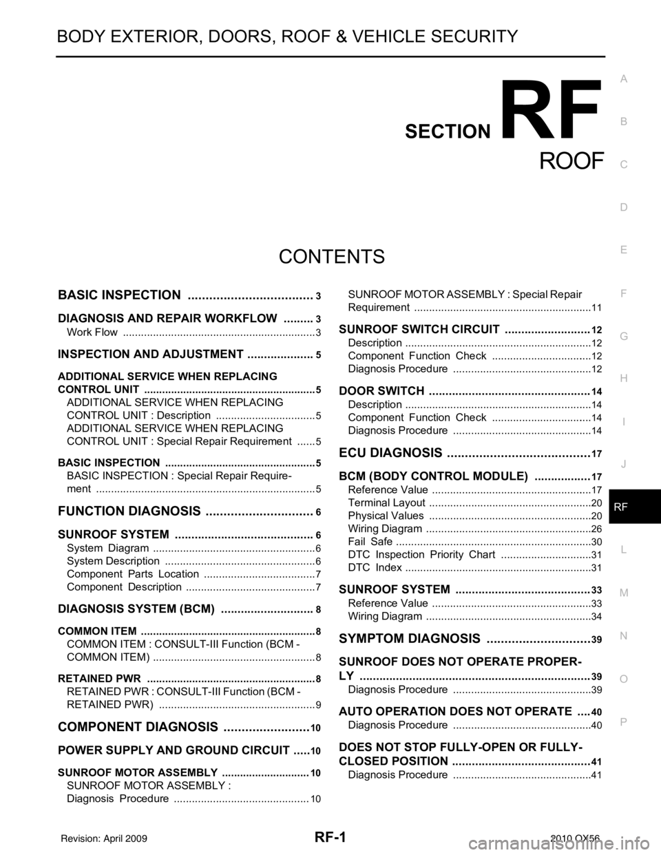
CONTENTS
ROOF
BASIC INSPECTION ....... .............................3
DIAGNOSIS AND REPAIR WORKFLOW ..... .....3
Work Flow ........................................................... ......3
INSPECTION AND ADJUSTMENT .....................5
ADDITIONAL SERVICE WHEN REPLACING
CONTROL UNIT .................................................... ......
5
ADDITIONAL SERVICE WHEN REPLACING
CONTROL UNIT : Description ..................................
5
ADDITIONAL SERVICE WHEN REPLACING
CONTROL UNIT : Special Repair Requirement .......
5
BASIC INSPECTION ...................................................5
BASIC INSPECTION : Spec ial Repair Require-
ment .................................................................... ......
5
FUNCTION DIAGNOSIS ...............................6
SUNROOF SYSTEM ...................................... .....6
System Diagram ................................................. ......6
System Description ...................................................6
Component Parts Location ......................................7
Component Description ............................................7
DIAGNOSIS SYSTEM (BCM) .............................8
COMMON ITEM ..................................................... ......8
COMMON ITEM : CONSULT-III Function (BCM -
COMMON ITEM) .......................................................
8
RETAINED PWR .........................................................8
RETAINED PWR : CONSULT-III Function (BCM -
RETAINED PWR) .....................................................
9
COMPONENT DIAGNOSIS .........................10
POWER SUPPLY AND GROUND CIRCUIT .. ....10
SUNROOF MOTOR ASSEMBLY .......................... ....10
SUNROOF MOTOR ASSEMBLY :
Diagnosis Procedure ..............................................
10
SUNROOF MOTOR ASSEMBLY : Special Repair
Requirement ........................................................ ....
11
SUNROOF SWITCH CIRCUIT ..........................12
Description ...............................................................12
Component Function Check ..................................12
Diagnosis Procedure ...............................................12
DOOR SWITCH .................................................14
Description ...............................................................14
Component Function Check ..................................14
Diagnosis Procedure ...............................................14
ECU DIAGNOSIS .........................................17
BCM (BODY CONTROL MODULE) .................17
Reference Value .................................................. ....17
Terminal Layout .......................................................20
Physical Values ................................................... ....20
Wiring Diagram ........................................................26
Fail Safe ..................................................................30
DTC Inspection Priority Chart ...............................31
DTC Index ...............................................................31
SUNROOF SYSTEM .........................................33
Reference Value ......................................................33
Wiring Diagram ........................................................34
SYMPTOM DIAGNOSIS ..............................39
SUNROOF DOES NOT OPERATE PROPER-
LY ......................................................................
39
Diagnosis Procedure ........................................... ....39
AUTO OPERATION DOES NOT OPERATE ....40
Diagnosis Procedure ...............................................40
DOES NOT STOP FULLY-OPEN OR FULLY-
CLOSED POSITION ..........................................
41
Diagnosis Procedure ...............................................41
Revision: April 20092010 QX56
Page 3134 of 4210
RF-6
< FUNCTION DIAGNOSIS >
SUNROOF SYSTEM
FUNCTION DIAGNOSIS
SUNROOF SYSTEM
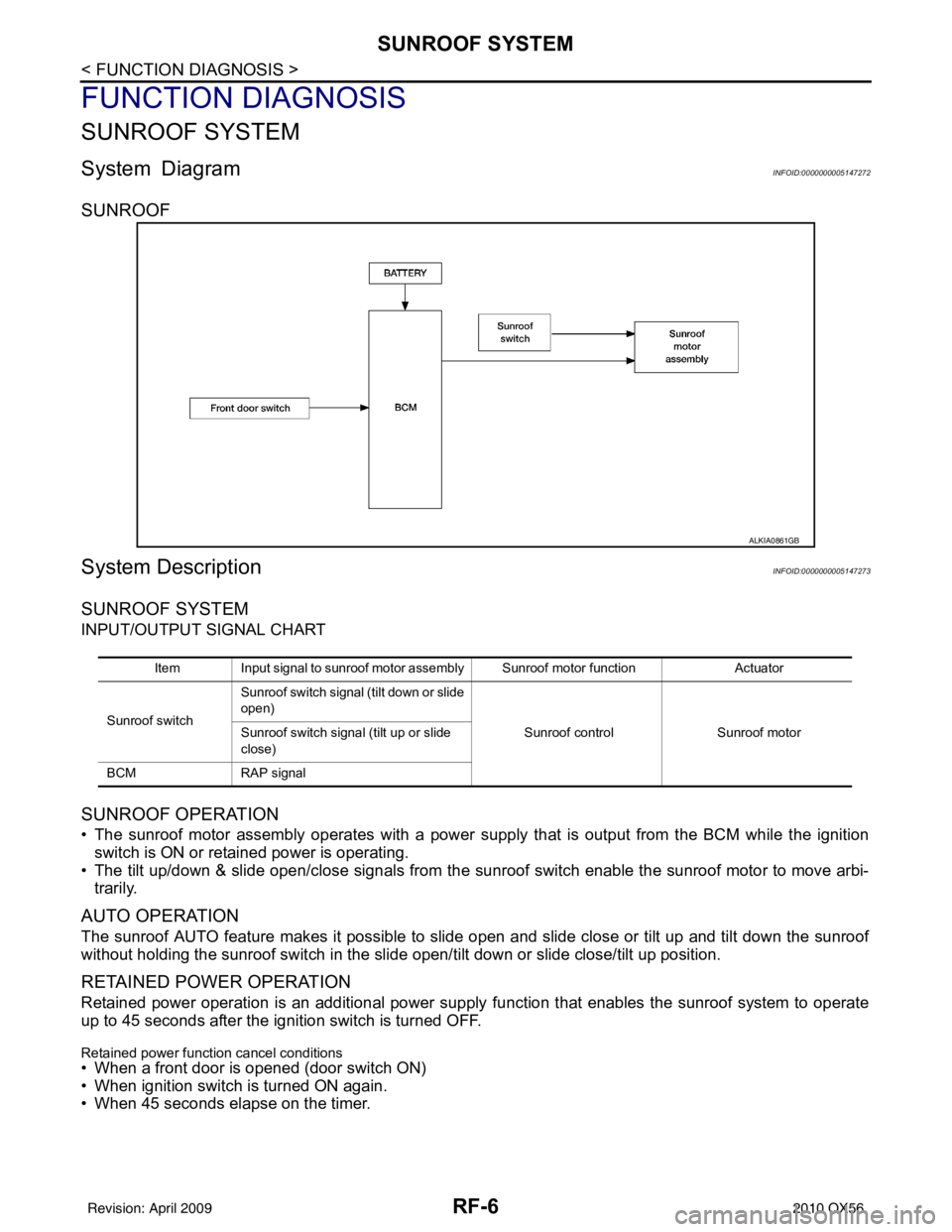
System DiagramINFOID:0000000005147272
SUNROOF
System DescriptionINFOID:0000000005147273
SUNROOF SYSTEM
INPUT/OUTPUT SIGNAL CHART
SUNROOF OPERATION
• The sunroof motor assembly operates with a power supply that is output from the BCM while the ignition
switch is ON or retained power is operating.
• The tilt up/down & slide open/close signals from the sunr oof switch enable the sunroof motor to move arbi-
trarily.
AUTO OPERATION
The sunroof AUTO feature makes it possible to sli de open and slide close or tilt up and tilt down the sunroof
without holding the sunroof switch in the slide open/tilt down or slide close/tilt up position.
RETAINED POWER OPERATION
Retained power operation is an additional power supply function that enables the sunroof system to operate
up to 45 seconds after the ignition switch is turned OFF.
Retained power function cancel conditions
• When a front door is opened (door switch ON)
• When ignition switch is turned ON again.
• When 45 seconds elapse on the timer.
ALKIA0861GB
Item Input signal to sunroof motor assembly Sunroof motor function Actuator
Sunroof switch Sunroof switch signal (tilt down or slide
open)
Sunroof controlSunroof motor
Sunroof switch signal (tilt up or slide
close)
BCM RAP signal
Revision: April 20092010 QX56
Page 3138 of 4210
RF-10
< COMPONENT DIAGNOSIS >
POWER SUPPLY AND GROUND CIRCUIT
COMPONENT DIAGNOSIS
POWER SUPPLY AND GROUND CIRCUIT
SUNROOF MOTOR ASSEMBLY
SUNROOF MOTOR ASSEMBLY : Diagnosis ProcedureINFOID:0000000005147278
Regarding Wiring Diagram information, refer to RF-34, "Wiring Diagram".
SUNROOF MOTOR ASSEMBLY
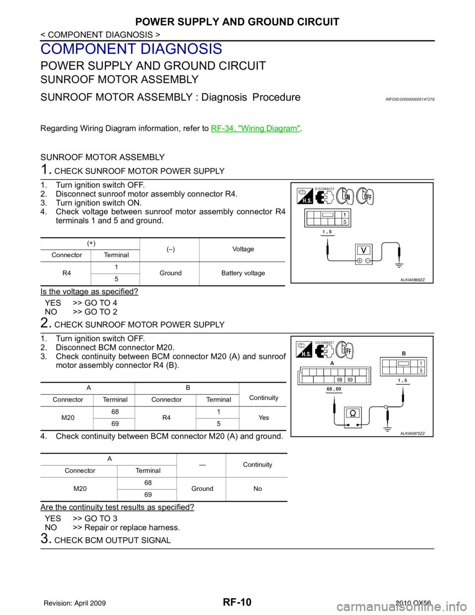
1. CHECK SUNROOF MOTOR POWER SUPPLY
1. Turn ignition switch OFF.
2. Disconnect sunroof motor assembly connector R4.
3. Turn ignition switch ON.
4. Check voltage between sunroof motor assembly connector R4 terminals 1 and 5 and ground.
Is the voltage as specified?
YES >> GO TO 4
NO >> GO TO 2
2. CHECK SUNROOF MOTOR POWER SUPPLY
1. Turn ignition switch OFF.
2. Disconnect BCM connector M20.
3. Check continuity between BCM connector M20 (A) and sunroof motor assembly connector R4 (B).
4. Check continuity between BCM connector M20 (A) and ground.
Are the continuity test results as specified?
YES >> GO TO 3
NO >> Repair or replace harness.
3. CHECK BCM OUTPUT SIGNAL
(+) (–)Voltage
Connector Terminal
R4 1
Ground Battery voltage
5
ALKIA0868ZZ
AB
Continuity
Connector Terminal Connector Terminal
M20 68
R4 1
Ye s
69 5
A —Contin u it y
Connector Terminal
M20 68
Ground No
69
ALKIA0870ZZ
Revision: April 20092010 QX56
Page 3140 of 4210
RF-12
< COMPONENT DIAGNOSIS >
SUNROOF SWITCH CIRCUIT
SUNROOF SWITCH CIRCUIT
DescriptionINFOID:0000000005147280
The BCM supplies power to the integrated CPU of the sunroof motor assembly. The tilt and slide functions of
the sunroof motor assembly is controlled by the sunroof switch.
Component Function CheckINFOID:0000000005147281
1. CHECK SUNROOF MOTOR FUNCTION
Do tilt up/down & slide open/close functi ons operate normally with sunroof switch?
Is the inspection result normal?
YES >> Sunroof motor assembly is OK.
NO >> Refer to RF-12, "
Diagnosis Procedure".
Diagnosis ProcedureINFOID:0000000005147282
Regarding Wiring Diagram information, refer to RF-34, "Wiring Diagram".
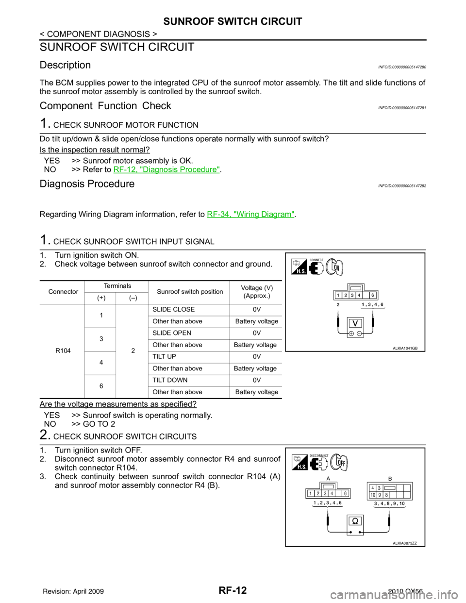
1. CHECK SUNROOF SWITCH INPUT SIGNAL
1. Turn ignition switch ON.
2. Check voltage between sunroof switch connector and ground.
Are the voltage measurements as specified?
YES >> Sunroof switch is operating normally.
NO >> GO TO 2
2. CHECK SUNROOF SWITCH CIRCUITS
1. Turn ignition switch OFF.
2. Disconnect sunroof motor assembly connector R4 and sunroof switch connector R104.
3. Check continuity between sunroof switch connector R104 (A) and sunroof motor assembly connector R4 (B).
Connector Te r m i n a l s
Sunroof switch position Voltage (V)
(Approx.)
(+) (–)
R104 1
2SLIDE CLOSE
0V
Other than above Battery voltage
3 SLIDE OPEN
0V
Other than above Battery voltage
4 TILT UP
0V
Other than above Battery voltage
6 TILT DOWN
0V
Other than above Battery voltage
ALKIA1041GB
ALKIA0873ZZ
Revision: April 20092010 QX56
Page 3142 of 4210
RF-14
< COMPONENT DIAGNOSIS >
DOOR SWITCH
DOOR SWITCH
DescriptionINFOID:0000000005147283
Detects door open/close condition.
Component Function CheckINFOID:0000000005147284
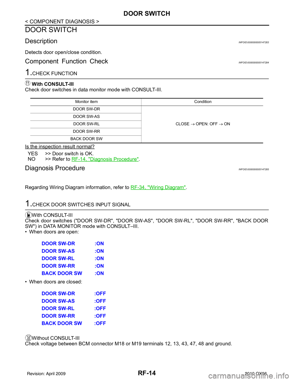
1.CHECK FUNCTION
With CONSULT-III
Check door switches in data monitor mode with CONSULT-III.
Is the inspection result normal?
YES >> Door switch is OK.
NO >> Refer to RF-14, "
Diagnosis Procedure".
Diagnosis ProcedureINFOID:0000000005147285
Regarding Wiring Diagram information, refer to RF-34, "Wiring Diagram".
1.CHECK DOOR SWITCHES INPUT SIGNAL
With CONSULT-III
Check door switches ("DOOR SW-DR", "DOOR SW-AS", "DOOR SW-RL", "DOOR SW-RR", "BACK DOOR
SW") in DATA MONITOR mode with CONSULT–III.
• When doors are open:
• When doors are closed:
Without CONSULT-III
Check voltage between BCM connector M18 or M19 terminals 12, 13, 43, 47, 48 and ground.
Monitor item Condition
DOOR SW-DR
CLOSE → OPEN: OFF → ON
DOOR SW-AS
DOOR SW-RL
DOOR SW-RR
BACK DOOR SW
DOOR SW-DR :ON
DOOR SW-AS :ON
DOOR SW-RL :ON
DOOR SW-RR :ON
BACK DOOR SW :ON
DOOR SW-DR :OFF
DOOR SW-AS :OFF
DOOR SW-RL :OFF
DOOR SW-RR :OFF
BACK DOOR SW :OFF
Revision: April 20092010 QX56
Page 3154 of 4210
RF-26
< ECU DIAGNOSIS >
BCM (BODY CONTROL MODULE)
Wiring Diagram
INFOID:0000000005370300
ABMWA0374GB
Revision: April 20092010 QX56