Page 3029 of 4210

PWC-44
< COMPONENT DIAGNOSIS >
REAR POWER VENT WINDOW SWITCH CIRCUIT CHECK
REAR POWER VENT WINDOW SWITCH CIRCUIT CHECK
DescriptionINFOID:0000000005147226
Rear power vent window motor LH and RH will be operated if rear power vent window switch is operated.
Diagnosis ProcedureINFOID:0000000005147227
Regarding Wiring Diagram information, refer to PWC-53, "Wiring Diagram".
1. CHECK REAR POWER VENT WINDOW SWITCH OPERATION
1. Turn ignition switch OFF.
2. Disconnect rear power vent window switch.
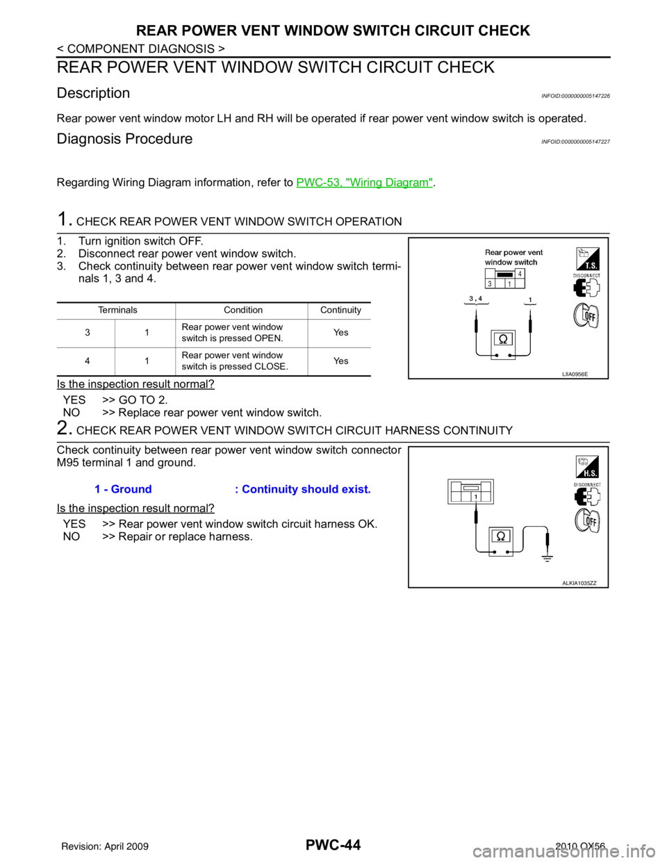
3. Check continuity between rear power vent window switch termi- nals 1, 3 and 4.
Is the inspection result normal?
YES >> GO TO 2.
NO >> Replace rear power vent window switch.
2. CHECK REAR POWER VENT WINDOW SWITCH CIRCUIT HARNESS CONTINUITY
Check continuity between rear power vent window switch connector
M95 terminal 1 and ground.
Is the inspection result normal?
YES >> Rear power vent window switch circuit harness OK.
NO >> Repair or replace harness.
Terminals Condition Continuity
31 Rear power vent window
switch is pressed OPEN. Ye s
41 Rear power vent window
switch is pressed CLOSE.
Ye s
LIIA0956E
1 - Ground
: Continuity should exist.
ALKIA1035ZZ
Revision: April 20092010 QX56
Page 3030 of 4210

REAR POWER VENT WINDOW MOTOR LH CIRCUIT CHECK
PWC-45
< COMPONENT DIAGNOSIS >
C
D E
F
G H
I
J
L
M A
B
PWC
N
O P
REAR POWER VENT WINDOW MOTOR LH CIRCUIT CHECK
DescriptionINFOID:0000000005147228
Rear power vent windows OPEN/CLOSE by receiving the signal from rear power vent window switch.
Diagnosis ProcedureINFOID:0000000005147229
Regarding Wiring Diagram information, refer to PWC-53, "Wiring Diagram".
1. CHECK REAR POWER VENT WINDOW LH SIGNAL
1. Turn ignition switch OFF.
2. Disconnect rear power vent window motor LH.
3. Turn ignition switch ON.
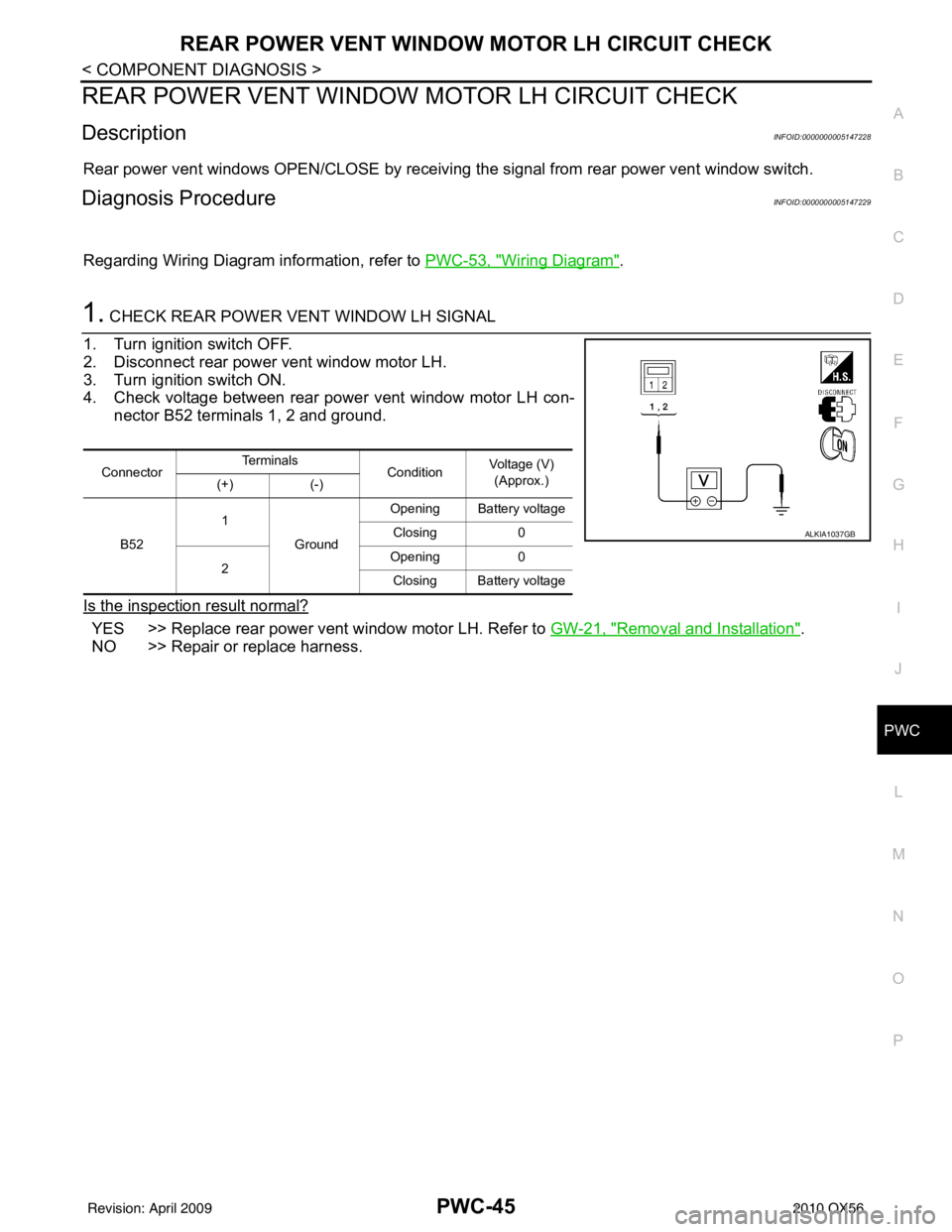
4. Check voltage between rear power vent window motor LH con- nector B52 terminals 1, 2 and ground.
Is the inspection result normal?
YES >> Replace rear power vent window motor LH. Refer to GW-21, "Removal and Installation".
NO >> Repair or replace harness.
Connector Te r m i n a l s
ConditionVoltage (V)
(Approx.)
(+) (-)
B52 1
Ground Opening Battery voltage
Closing 0
2 Opening
0
Closing Battery voltage
ALKIA1037GB
Revision: April 20092010 QX56
Page 3031 of 4210
PWC-46
< COMPONENT DIAGNOSIS >
REAR POWER VENT WINDOW MOTOR RH CIRCUIT CHECK
REAR POWER VENT WINDOW MOTOR RH CIRCUIT CHECK
DescriptionINFOID:0000000005147230
Rear power vent windows OPEN/CLOSE by receiving the signal from rear power vent window switch.
Diagnosis ProcedureINFOID:0000000005147231
Regarding Wiring Diagram information, refer to PWC-53, "Wiring Diagram".
1.CHECK REAR POWER VENT WINDOW SWITCH RH SIGNAL
1. Turn ignition switch OFF.
2. Disconnect rear power vent window motor RH.
3. Turn ignition switch ON.
4. Check voltage between rear power vent window motor LH con- nector B150 terminals 1, 2 and ground.
Is the inspection result normal?
YES >> Replace rear power vent window motor RH. Refer to GW-21, "Removal and Installation".
NO >> Repair or replace harness.
Connector Te r m i n a l s
ConditionVoltage (V)
(Approx.)
(+) (-)
B150 1
Ground Opening Battery voltage
Closing 0
2 Opening
0
Closing Battery voltage
ALKIA1037GB
Revision: April 20092010 QX56
Page 3032 of 4210

REAR POWER VENT WINDOW RELAY (OPEN) CHECK
PWC-47
< COMPONENT DIAGNOSIS >
C
D E
F
G H
I
J
L
M A
B
PWC
N
O P
REAR POWER VENT WINDOW RELAY (OPEN) CHECK
DescriptionINFOID:0000000005147232
Rear power vent windows OPEN/CLOSE by receiving the signal from rear power vent window switch.
Diagnosis ProcedureINFOID:0000000005147233
Regarding Wiring Diagram information, refer to PWC-53, "Wiring Diagram".
1.CHECK REAR POWER VENT WINDOW RELAY (OPEN) POWER SUPPLY CIRCUIT
1. Turn ignition switch OFF.
2. Disconnect rear power vent window relay (OPEN).
3. Turn ignition switch ON.
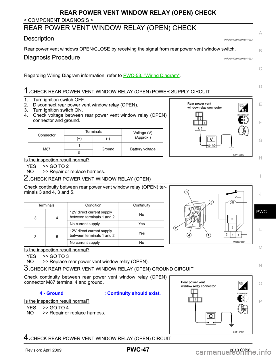
4. Check voltage between rear power vent window relay (OPEN) connector and ground.
Is the inspection result normal?
YES >> GO TO 2
NO >> Repair or replace harness.
2.CHECK REAR POWER VENT WINDOW RELAY (OPEN)
Check continuity between rear power vent window relay (OPEN) ter-
minals 3 and 4, 3 and 5.
Is the inspection result normal?
YES >> GO TO 3
NO >> Replace rear power vent window relay (OPEN).
3.CHECK REAR POWER VENT WINDOW RELAY (OPEN) GROUND CIRCUIT
Check continuity between rear power vent window relay (OPEN)
connector M87 terminal 4 and ground.
Is the inspection result normal?
YES >> GO TO 4
NO >> Repair or replace harness.
4.CHECK REAR POWER VENT WI NDOW RELAY (OPEN) CIRCUIT
ConnectorTe r m i n a l s
Voltage (V)
(Approx.)
(+) (-)
M87 1
Ground Battery voltage
5
LIIA1565E
Terminals Condition Continuity
34 12V direct current supply
between terminals 1 and 2
No
No current supply Yes
35 12V direct current supply
between terminals 1 and 2
Ye s
No current supply No
WIIA0291E
4 - Ground: Continuity should exist.
LIIA1567E
Revision: April 20092010 QX56
Page 3034 of 4210

REAR POWER VENT WINDOW RELAY (CLOSE) CHECKPWC-49
< COMPONENT DIAGNOSIS >
C
DE
F
G H
I
J
L
M A
B
PWC
N
O P
REAR POWER VENT WINDOW RELAY (CLOSE) CHECK
DescriptionINFOID:0000000005147234
Rear power vent windows OPEN/CLOSE by receiving the signal from rear power vent window switch.
Diagnosis ProcedureINFOID:0000000005147235
Regarding Wiring Diagram information, refer to PWC-53, "Wiring Diagram".
1.CHECK REAR POWER VENT WINDOW RELAY (CLOSE) POWER SUPPLY CIRCUIT
1. Turn ignition switch OFF.
2. Disconnect rear power vent window relay (CLOSE).
3. Turn ignition switch ON.
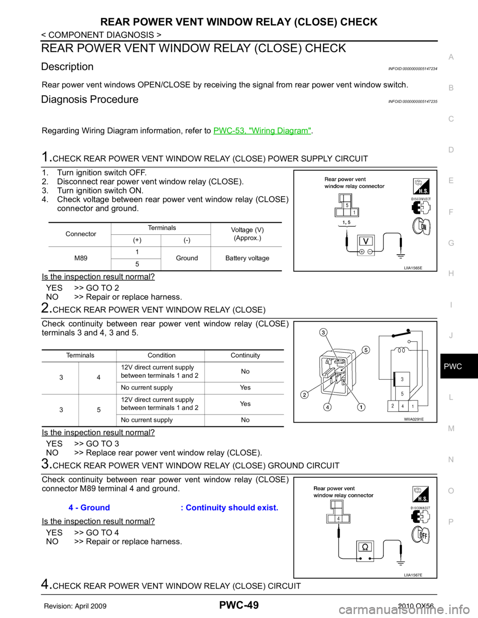
4. Check voltage between rear power vent window relay (CLOSE) connector and ground.
Is the inspection result normal?
YES >> GO TO 2
NO >> Repair or replace harness.
2.CHECK REAR POWER VENT WINDOW RELAY (CLOSE)
Check continuity between rear pow er vent window relay (CLOSE)
terminals 3 and 4, 3 and 5.
Is the inspection result normal?
YES >> GO TO 3
NO >> Replace rear power vent window relay (CLOSE).
3.CHECK REAR POWER VENT WINDOW RELAY (CLOSE) GROUND CIRCUIT
Check continuity between rear pow er vent window relay (CLOSE)
connector M89 terminal 4 and ground.
Is the inspection result normal?
YES >> GO TO 4
NO >> Repair or replace harness.
4.CHECK REAR POWER VENT WI NDOW RELAY (CLOSE) CIRCUIT
ConnectorTe r m i n a l s
Voltage (V)
(Approx.)
(+) (-)
M89 1
Ground Battery voltage
5
LIIA1565E
Terminals Condition Continuity
34 12V direct current supply
between terminals 1 and 2
No
No current supply Yes
35 12V direct current supply
between terminals 1 and 2
Ye s
No current supply No
WIIA0291E
4 - Ground: Continuity should exist.
LIIA1567E
Revision: April 20092010 QX56
Page 3038 of 4210
POWER WINDOW MAIN SWITCHPWC-53
< ECU DIAGNOSIS >
C
DE
F
G H
I
J
L
M A
B
PWC
N
O P
Wiring DiagramINFOID:0000000005147241
ABKWA0485GB
Revision: April 20092010 QX56
Page 3053 of 4210
PWC-68
< ECU DIAGNOSIS >
FRONT POWER WINDOW SWITCH
Wiring Diagram
INFOID:0000000005367566
ABKWA0485GB
Revision: April 20092010 QX56
Page 3075 of 4210
PWC-90
< ECU DIAGNOSIS >
BCM (BODY CONTROL MODULE)
Wiring Diagram
INFOID:0000000005367562
ABMWA0374GB
Revision: April 20092010 QX56