2010 INFINITI QX56 diagram
[x] Cancel search: diagramPage 3010 of 4210
ENCODERPWC-25
< COMPONENT DIAGNOSIS >
C
DE
F
G H
I
J
L
M A
B
PWC
N
O P
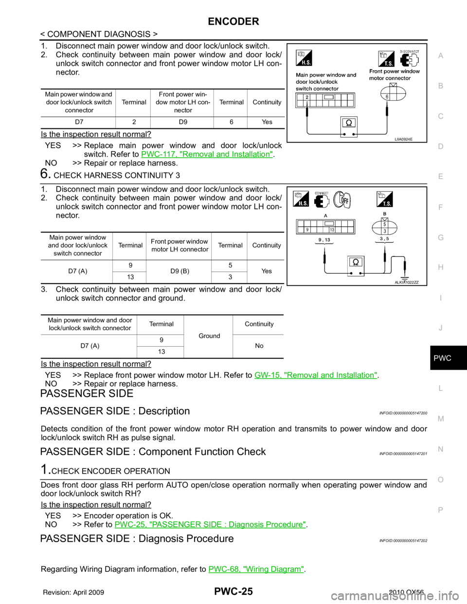
1. Disconnect main power window and door lock/unlock switch.
2. Check continuity between main power window and door lock/ unlock switch connector and front power window motor LH con-
nector.
Is the inspection result normal?
YES >> Replace main power window and door lock/unlock switch. Refer to PWC-117, "
Removal and Installation".
NO >> Repair or replace harness.
6. CHECK HARNESS CONTINUITY 3
1. Disconnect main power window and door lock/unlock switch.
2. Check continuity between main power window and door lock/ unlock switch connector and front power window motor LH con-
nector.
3. Check continuity between main power window and door lock/ unlock switch connector and ground.
Is the inspection result normal?
YES >> Replace front power wi ndow motor LH. Refer to GW-15, "Removal and Installation".
NO >> Repair or replace harness.
PASSENGER SIDE
PASSENGER SIDE : DescriptionINFOID:0000000005147200
Detects condition of the front power window motor RH operation and transmits to power window and door
lock/unlock switch RH as pulse signal.
PASSENGER SIDE : Comp onent Function CheckINFOID:0000000005147201
1.CHECK ENCODER OPERATION
Does front door glass RH perform AUTO open/close operation normally when operating power window and
door lock/unlock switch RH?
Is the inspection result normal?
YES >> Encoder operation is OK.
NO >> Refer to PWC-25, "
PASSENGER SIDE : Diagnosis Procedure".
PASSENGER SIDE : Dia gnosis ProcedureINFOID:0000000005147202
Regarding Wiring Diagram information, refer to PWC-68, "Wiring Diagram".
Main power window and
door lock/unlock switch
connector Te r m i n a l
Front power win-
dow motor LH con-
nector Terminal Continuity
D7 2 D9 6 Yes
LIIA0924E
Main power window
and door lock/unlock switch connector Te r m i n a l
Front power window
motor LH connector Terminal Continuity
D7 (A) 9
D9 (B) 5
Ye s
13 3
Main power window and door lock/unlock switch connector Te r m i n a l
GroundContinuity
D7 (A) 9
No
13
ALKIA1022ZZ
Revision: April 20092010 QX56
Page 3013 of 4210
PWC-28
< COMPONENT DIAGNOSIS >
ENCODER
Is the inspection result normal?
YES >> Replace front power window motor RH. Refer to GW-15, "Removal and Installation".
NO >> Repair or replace harness.
REAR LH
REAR LH : DescriptionINFOID:0000000005147203
Detects condition of the front power window motor LH operation and transmits to main power window and door
lock/unlock switch as pulse signal.
REAR LH : Componen t Function CheckINFOID:0000000005147204
1. CHECK ENCODER OPERATION
Does front door glass LH perform AUTO open/close operation normally when operating main power window
and door lock/unlock switch?
Is the inspection result normal?
YES >> Encoder operation is OK.
NO >> Refer to PWC-31, "
REAR RH : Diagnosis Procedure".
REAR LH : Diagnosis ProcedureINFOID:0000000005147205
Regarding Wiring Diagram information, refer to PWC-53, "Wiring Diagram".
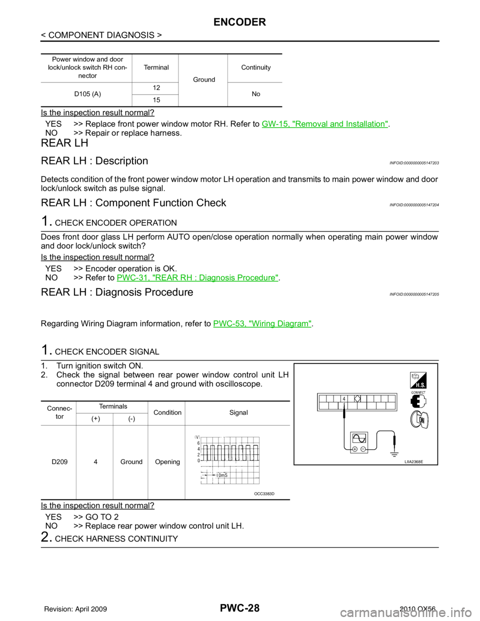
1. CHECK ENCODER SIGNAL
1. Turn ignition switch ON.
2. Check the signal between rear power window control unit LH connector D209 terminal 4 and ground with oscilloscope.
Is the inspection result normal?
YES >> GO TO 2
NO >> Replace rear power window control unit LH.
2. CHECK HARNESS CONTINUITY
Power window and door
lock/unlock switch RH con-
nector Te r m i n a l
GroundContinuity
D105 (A) 12
No
15
Connec-
tor Te r m i n a l s
Condition Signal
(+) (-)
D209 4 Ground Opening
LIIA2368E
OCC3383D
Revision: April 20092010 QX56
Page 3016 of 4210
ENCODERPWC-31
< COMPONENT DIAGNOSIS >
C
DE
F
G H
I
J
L
M A
B
PWC
N
O P
REAR RH : DescriptionINFOID:0000000005147206
Detects condition of the front power window motor LH operation and transmits to main power window and door
lock/unlock switch as pulse signal.
REAR RH : Component Function CheckINFOID:0000000005147207
1. CHECK ENCODER OPERATION
Does front door glass RH perform AUTO open/close operation normally when operating main power window
and door lock/unlock switch?
Is the inspection result normal?
YES >> Encoder operation is OK.
NO >> Refer to PWC-31, "
REAR RH : Diagnosis Procedure".
REAR RH : Diagnosis ProcedureINFOID:0000000005147208
Regarding Wiring Diagram information, refer to PWC-53, "Wiring Diagram".
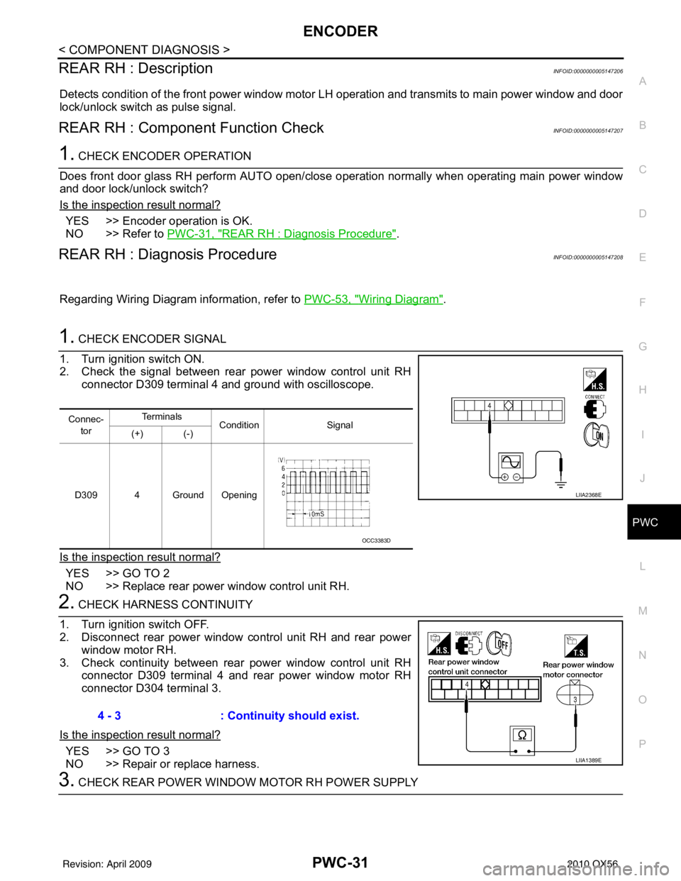
1. CHECK ENCODER SIGNAL
1. Turn ignition switch ON.
2. Check the signal between rear power window control unit RH connector D309 terminal 4 and ground with oscilloscope.
Is the inspection result normal?
YES >> GO TO 2
NO >> Replace rear power window control unit RH.
2. CHECK HARNESS CONTINUITY
1. Turn ignition switch OFF.
2. Disconnect rear power window control unit RH and rear power window motor RH.
3. Check continuity between rear power window control unit RH connector D309 terminal 4 and rear power window motor RH
connector D304 terminal 3.
Is the inspection result normal?
YES >> GO TO 3
NO >> Repair or replace harness.
3. CHECK REAR POWER WINDOW MOTOR RH POWER SUPPLY
Connec- tor Te r m i n a l s
Condition Signal
(+) (-)
D309 4 Ground Opening
LIIA2368E
OCC3383D
4 - 3 : Continuity should exist.
LIIA1389E
Revision: April 20092010 QX56
Page 3019 of 4210
PWC-34
< COMPONENT DIAGNOSIS >
DOOR SWITCH
DOOR SWITCH
DescriptionINFOID:0000000005147209
Detects door open/close condition and transmits the signal to BCM.
Component Function CheckINFOID:0000000005147210
1. CHECK FRONT DOOR SWITCH INPUT SIGNAL
Check (“DOOR SW-DR” and “DOOR SW-AS”) in “DATA MONITOR” mode with CONSULT-III. Refer to BCS-
27, "RETAINED PWR : CONSULT-III Function (BCM - RETAINED PWR)".
Is the inspection result normal?
YES >> Front door switch circuit is OK.
NO >> Refer to PWC-34, "
Diagnosis Procedure".
Diagnosis ProcedureINFOID:0000000005147211
Regarding Wiring Diagram information, refer to PWC-53, "Wiring Diagram".
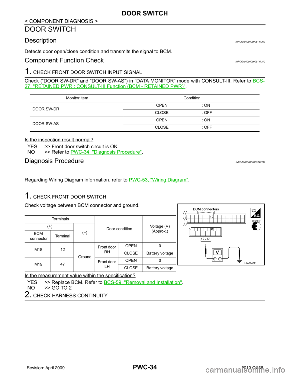
1. CHECK FRONT DOOR SWITCH
Check voltage between BCM connector and ground.
Is the measurement value within the specification?
YES >> Replace BCM. Refer to BCS-59, "Removal and Installation".
NO >> GO TO 2
2. CHECK HARNESS CONTINUITY
Monitor item Condition
DOOR SW-DR OPEN
: ON
CLOSE : OFF
DOOR SW-AS OPEN
: ON
CLOSE : OFF
Te r m i n a l s
Door conditionVoltage (V)
(Approx.)
(+)
(–)
BCM
connector Te r m i n a l
M18 12 GroundFront door
RH OPEN
0
CLOSE Battery voltage
M19 47 Front door
LH OPEN
0
CLOSE Battery voltage
LIIA0946E
Revision: April 20092010 QX56
Page 3021 of 4210
PWC-36
< COMPONENT DIAGNOSIS >
DOOR KEY CYLINDER SWITCH
DOOR KEY CYLINDER SWITCH
DescriptionINFOID:0000000005147213
Main power window and door lock/unlock switch detects condition of the door key cylinder and transmits to
BCM as the LOCK or UNLOCK signals.
Component Function CheckINFOID:0000000005147214
1. CHECK DOOR KEY CYLINDER SWITCH INPUT SIGNAL
Check (“KEY CYL LK-SW”, “KEY CYL UN-SW”) in “DAT A MONITOR” mode for “POWER DOOR LOCK SYS-
TEM” with CONSULT-III. Refer to DLK-56, "
CONSULT-III Function (INTELLIGENT KEY)".
Is the inspection result normal?
YES >> Key cylinder switch is OK.
NO >> Refer to PWC-36, "
Diagnosis Procedure".
Diagnosis ProcedureINFOID:0000000005147215
Regarding Wiring Diagram information, refer to PWC-53, "Wiring Diagram".
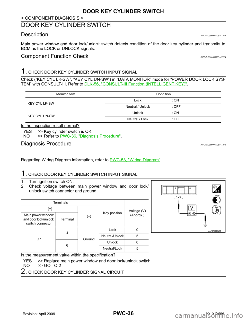
1. CHECK DOOR KEY CYLINDER SWITCH INPUT SIGNAL
1. Turn ignition switch ON.
2. Check voltage between main power window and door lock/ unlock switch connector and ground.
Is the measurement value within the specification?
YES >> Replace main power window and door lock/unlock switch.
NO >> GO TO 2
2. CHECK DOOR KEY CYLINDER SIGNAL CIRCUIT
Monitor item Condition
KEY CYL LK-SW Lock
: ON
Neutral / Unlock : OFF
KEY CYL UN-SW Unlock
: ON
Neutral / Lock : OFF
Te r m i n a l s
Key positionVoltage (V)
(Approx.)
(+)
(–)
Main power window
and door lock/unlock switch connector Te r m i n a l
D7 4
Ground Lock
0
Neutral/Unlock 5
6 Unlock
0
Neutral/Lock 5
ALKIA0309ZZ
Revision: April 20092010 QX56
Page 3024 of 4210
POWER WINDOW SERIAL LINKPWC-39
< COMPONENT DIAGNOSIS >
C
DE
F
G H
I
J
L
M A
B
PWC
N
O P
POWER WINDOW SERIAL LINK
POWER WINDOW MAIN SWITCH
POWER WINDOW MAIN SWITCH : DescriptionINFOID:0000000005147217
Main power window and door lock/unlock switch, power window and door lock/unlock switch RH and BCM
transmit and receive the signal by power window serial link.
The signal mentioned below is transmitted from BCM to main power window and door lock/unlock switch and
power window and door lock/unlock switch RH
• Keyless power window down signal
The signal mentioned below is transmitted from main pow er window and door lock/unlock switch to power win-
dow and door lock/unlock switch RH
• Front door window RH operation signal
• Power window control by key cylinder switch signal
• Power window lock switch signal
• Retained power operation signal
POWER WINDOW MAIN SWITCH : Component Function CheckINFOID:0000000005147218
1. CHECK MAIN POWER WINDOW AND DOOR LOCK/UNLOCK SWITCH OUTPUT SIGNAL
Check (“CDL LOCK SW ”, “CDL UNLOCK SW”) in “D ATA MONITOR” mode for “POWER DOOR LOCK SYS-
TEM” with CONSULT-III. Refer to BCS-17, "
DOOR LOCK : CONSULT-III Function (BCM - DOOR LOCK)".
Is the inspection result normal?
YES >> Power window serial link is OK.
NO >> Refer to PWC-39, "
POWER WINDOW MAIN SWITCH : Diagnosis Procedure".
POWER WINDOW MAIN SWITCH : Diagnosis ProcedureINFOID:0000000005147219
Regarding Wiring Diagram information, refer to PWC-53, "Wiring Diagram".
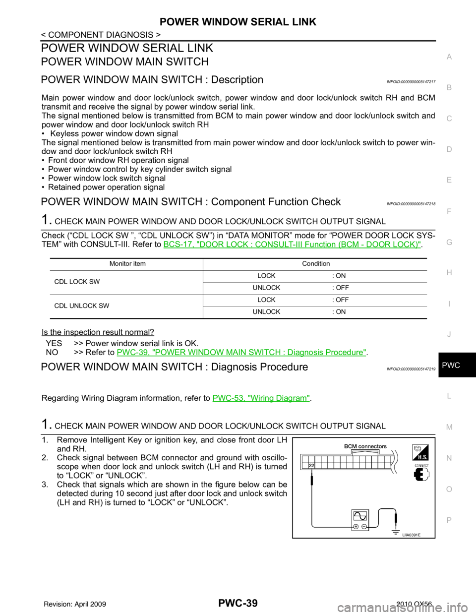
1. CHECK MAIN POWER WINDOW AND DOOR LOCK/UNLOCK SWITCH OUTPUT SIGNAL
1. Remove Intelligent Key or ignition key, and close front door LH and RH.
2. Check signal between BCM connector and ground with oscillo-
scope when door lock and unlock switch (LH and RH) is turned
to “LOCK” or “UNLOCK”.
3. Check that signals which are shown in the figure below can be
detected during 10 second just after door lock and unlock switch
(LH and RH) is turned to “LOCK” or “UNLOCK”.
Monitor item Condition
CDL LOCK SW LOCK
: ON
UNLOCK : OFF
CDL UNLOCK SW LOCK
: OFF
UNLOCK : ON
LIIA0391E
Revision: April 20092010 QX56
Page 3026 of 4210
POWER WINDOW SERIAL LINKPWC-41
< COMPONENT DIAGNOSIS >
C
DE
F
G H
I
J
L
M A
B
PWC
N
O P
Check (“CDL LOCK SW ”, “CDL UNLOCK SW”) in “D ATA MONITOR” mode for “POWER DOOR LOCK SYS-
TEM” with CONSULT-III. Refer to BCS-17, "
DOOR LOCK : CONSULT-III Function (BCM - DOOR LOCK)".
Is the inspection result normal?
YES >> Power window serial link is OK.
NO >> Refer to PWC-41, "
FRONT POWER WINDOW SWITCH : Diagnosis Procedure".
FRONT POWER WINDOW SWIT CH : Diagnosis ProcedureINFOID:0000000005147222
Regarding Wiring Diagram information, refer to PWC-68, "Wiring Diagram".
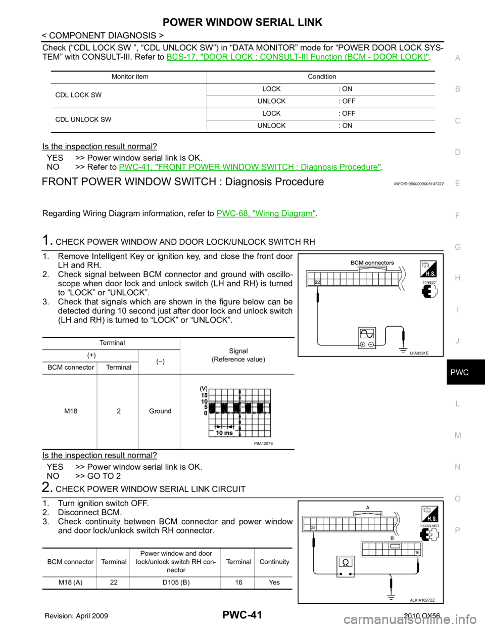
1. CHECK POWER WINDOW AND DOOR LOCK/UNLOCK SWITCH RH
1. Remove Intelligent Key or ignition key, and close the front door LH and RH.
2. Check signal between BCM connector and ground with oscillo-
scope when door lock and unlock switch (LH and RH) is turned
to “LOCK” or “UNLOCK”.
3. Check that signals which are shown in the figure below can be
detected during 10 second just after door lock and unlock switch
(LH and RH) is turned to “LOCK” or “UNLOCK”.
Is the inspection result normal?
YES >> Power window serial link is OK.
NO >> GO TO 2
2. CHECK POWER WINDOW SERIAL LINK CIRCUIT
1. Turn ignition switch OFF.
2. Disconnect BCM.
3. Check continuity between BCM connector and power window and door lock/unlock switch RH connector.
Monitor item Condition
CDL LOCK SW LOCK
: ON
UNLOCK : OFF
CDL UNLOCK SW LOCK
: OFF
UNLOCK : ON
Te r m i n a l
Signal
(Reference value)
(+)
(–)
BCM connector Terminal
M18 2 Ground
LIIA0391E
PIIA1297E
BCM connector Terminal Power window and door
lock/unlock switch RH con- nector Terminal Continuity
M18 (A) 22 D105 (B)16 Yes
ALKIA1027ZZ
Revision: April 20092010 QX56
Page 3027 of 4210
PWC-42
< COMPONENT DIAGNOSIS >
POWER WINDOW SERIAL LINK
4. Check continuity between BCM connector and ground.
Is the inspection result normal?
YES >> Replace main power window and door lock/unlock switch. Refer to PWC-117, "Removal and
Installation".
NO >> Repair or replace harness.
REAR POWER WINDOW SWITCH
REAR POWER WINDOW SWITCH : Power Window Serial Link Check Rear LH or RH
INFOID:0000000005147223
Regarding Wiring Diagram information, refer to PWC-53, "Wiring Diagram".
1. CHECK REAR POWER WINDOW CONTROL UNIT LH OR RH
1. Replace with operative rear power window control unit LH or RH.
2. Does window operate normally?
Is the inspection result normal?
YES >> Replace rear power window control unit LH or RH.
NO >> GO TO 2
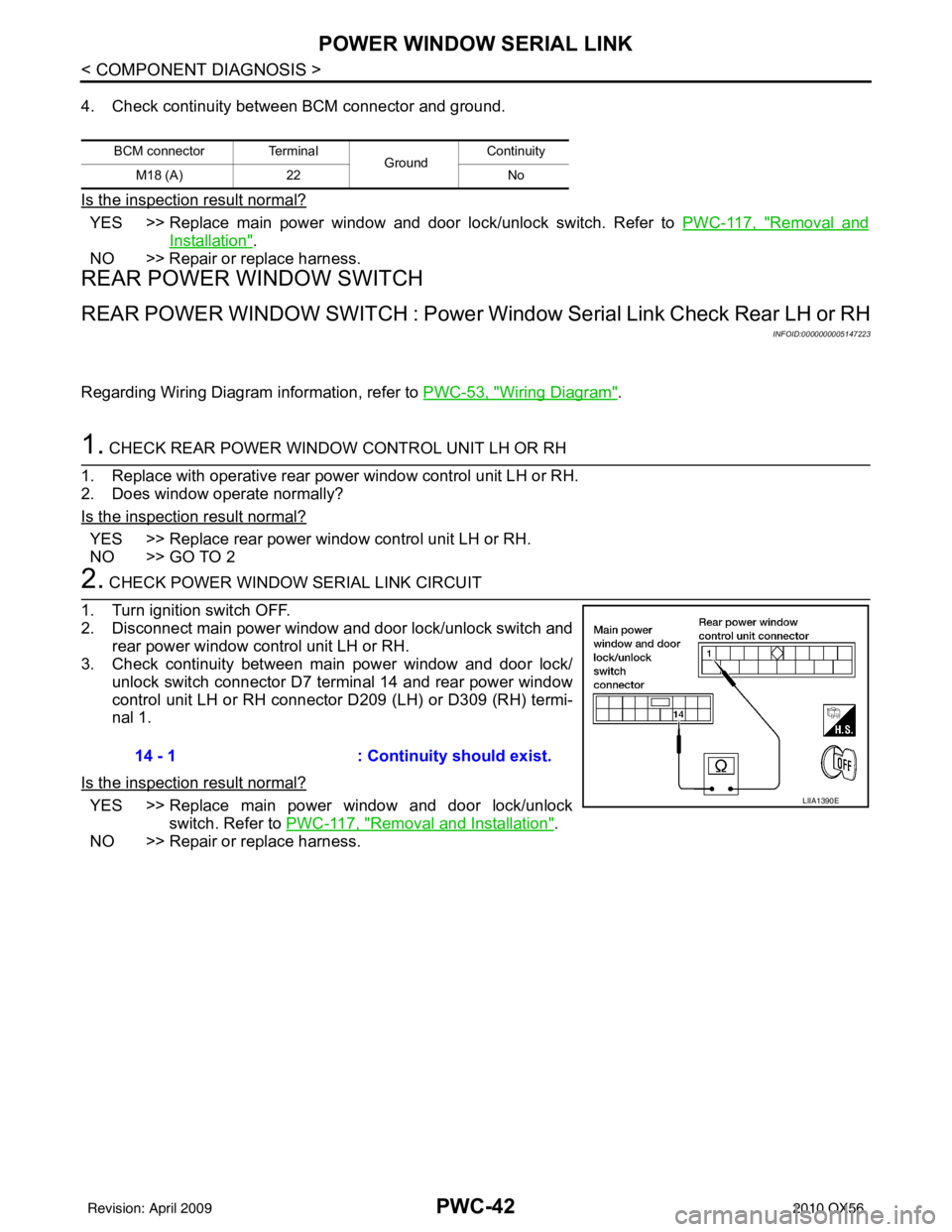
2. CHECK POWER WINDOW SERIAL LINK CIRCUIT
1. Turn ignition switch OFF.
2. Disconnect main power window and door lock/unlock switch and rear power window control unit LH or RH.
3. Check continuity between main power window and door lock/ unlock switch connector D7 terminal 14 and rear power window
control unit LH or RH connector D209 (LH) or D309 (RH) termi-
nal 1.
Is the inspection result normal?
YES >> Replace main power window and door lock/unlock switch. Refer to PWC-117, "
Removal and Installation".
NO >> Repair or replace harness.
BCM connector Terminal GroundContinuity
M18 (A) 22 No
14 - 1: Continuity should exist.
LIIA1390E
Revision: April 20092010 QX56