2009 SUBARU TRIBECA engine
[x] Cancel search: enginePage 1578 of 2453
FU(H6DO)-17
Engine Coolant Temperature Sensor
FUEL INJECTION (FUEL SYSTEMS)
4. Engine Coolant Temperature
Sensor
A: REMOVAL
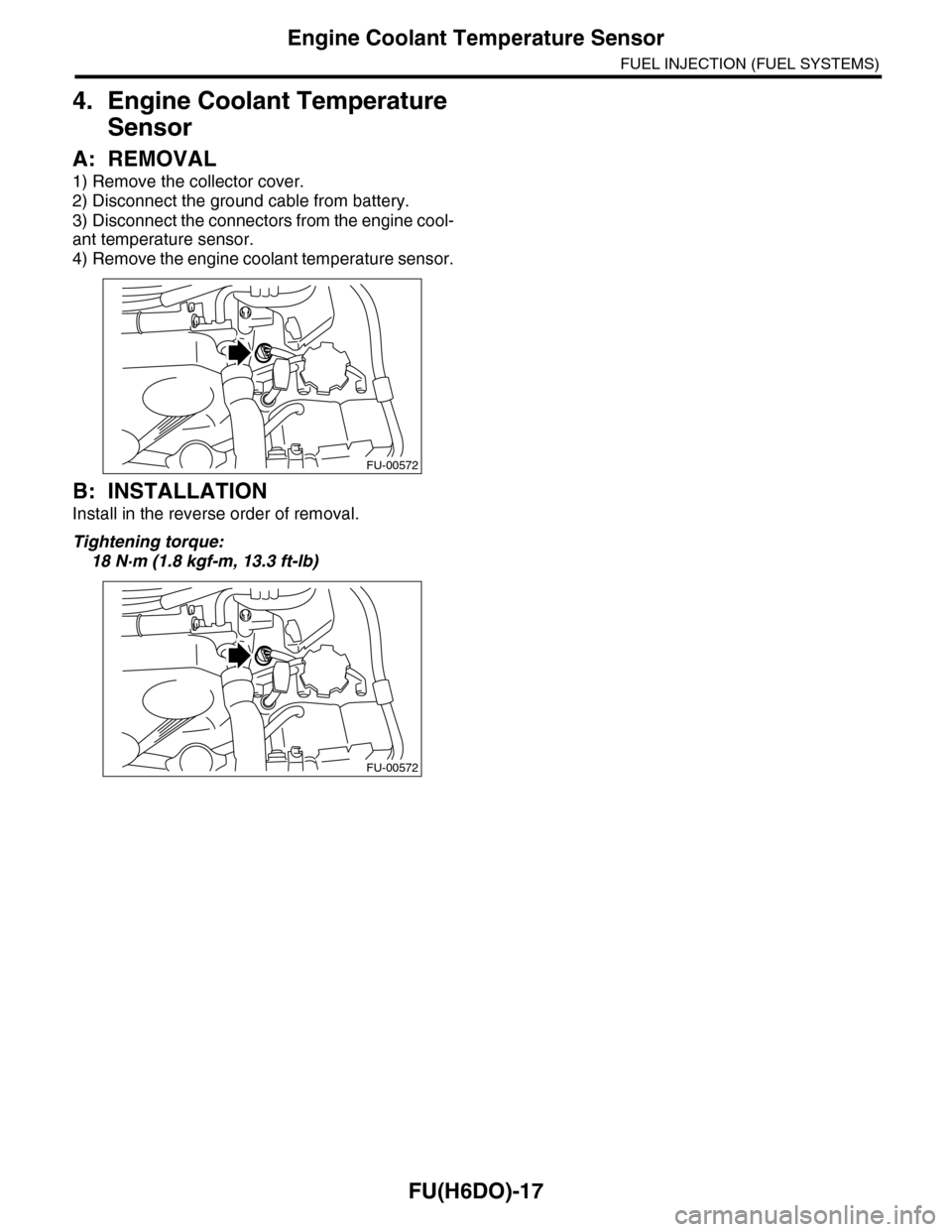
1) Remove the collector cover.
2) Disconnect the ground cable from battery.
3) Disconnect the connectors from the engine cool-
ant temperature sensor.
4) Remove the engine coolant temperature sensor.
B: INSTALLATION
Install in the reverse order of removal.
Tightening torque:
18 N·m (1.8 kgf-m, 13.3 ft-lb)
FU-00572
FU-00572
Page 1585 of 2453
FU(H6DO)-24
Fuel Injector
FUEL INJECTION (FUEL SYSTEMS)
11.Fuel Injector
A: REMOVAL
1. RH SIDE
1) Remove the collector cover.
2) Release the fuel pressure.
DURE, Fuel.>
3) Disconnect the ground cable from battery.
4) Open the fuel filler flap lid, and remove the fuel
filler cap.
5) Remove the air cleaner case.
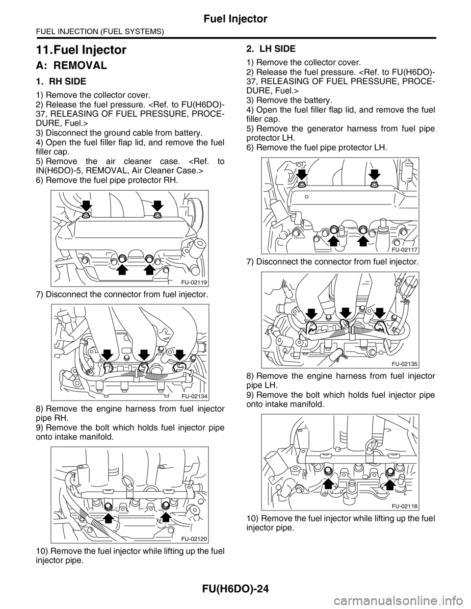
6) Remove the fuel pipe protector RH.
7) Disconnect the connector from fuel injector.
8) Remove the engine harness from fuel injector
pipe RH.
9) Remove the bolt which holds fuel injector pipe
onto intake manifold.
10) Remove the fuel injector while lifting up the fuel
injector pipe.
2. LH SIDE
1) Remove the collector cover.
2) Release the fuel pressure.
DURE, Fuel.>
3) Remove the battery.
4) Open the fuel filler flap lid, and remove the fuel
filler cap.
5) Remove the generator harness from fuel pipe
protector LH.
6) Remove the fuel pipe protector LH.
7) Disconnect the connector from fuel injector.
8) Remove the engine harness from fuel injector
pipe LH.
9) Remove the bolt which holds fuel injector pipe
onto intake manifold.
10) Remove the fuel injector while lifting up the fuel
injector pipe.
FU-02119
FU-02134
FU-02120
FU-02117
FU-02135
FU-02118
Page 1593 of 2453
FU(H6DO)-32
Engine Control Module (ECM)
FUEL INJECTION (FUEL SYSTEMS)
16.Engine Control Module (ECM)
A: REMOVAL
1) Disconnect the ground cable from battery.
2) Remove the front pillar lower trim and console
side panel lower RH of passenger's side.
3) Detach the floor mat of passenger's seat.
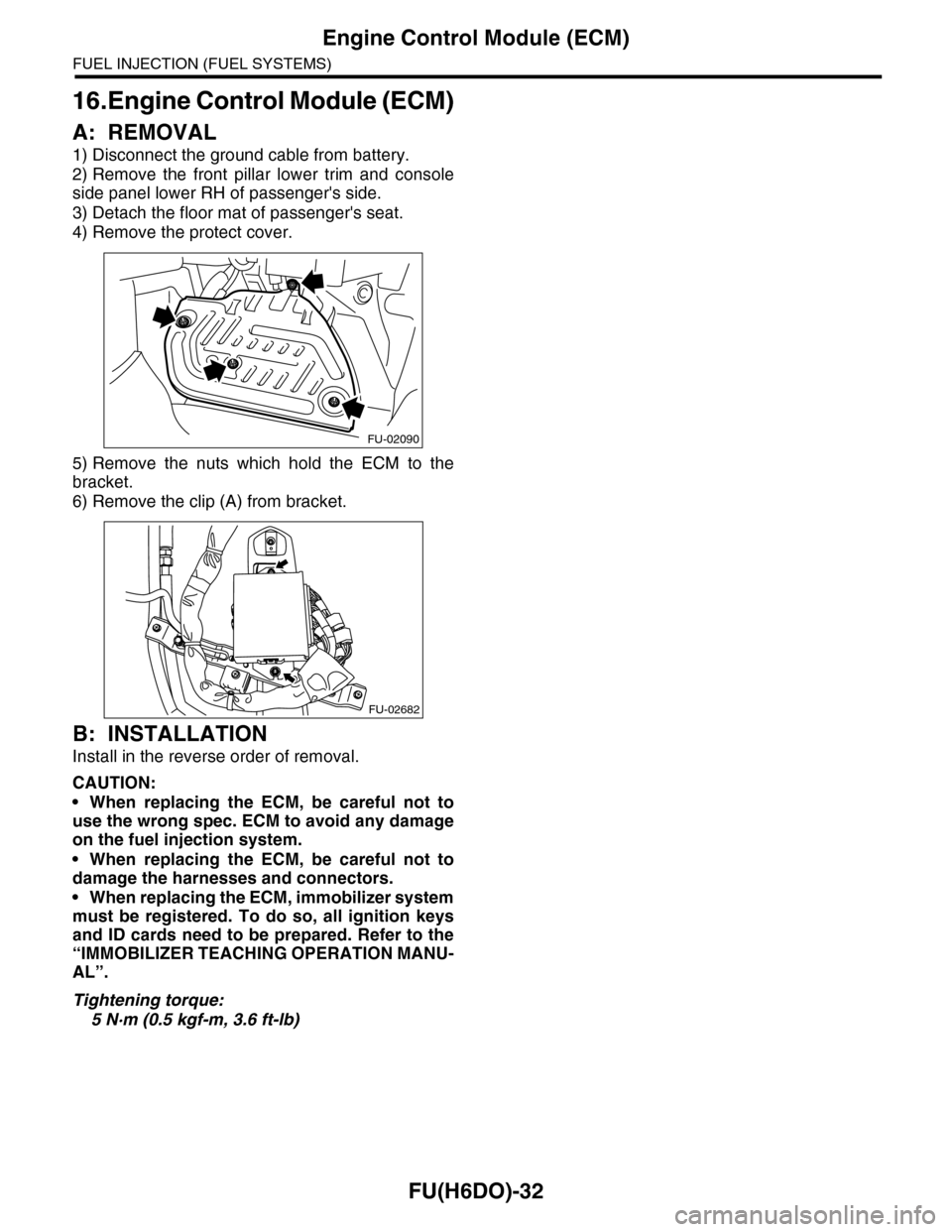
4) Remove the protect cover.
5) Remove the nuts which hold the ECM to the
bracket.
6) Remove the clip (A) from bracket.
B: INSTALLATION
Install in the reverse order of removal.
CAUTION:
•When replacing the ECM, be careful not to
use the wrong spec. ECM to avoid any damage
on the fuel injection system.
•When replacing the ECM, be careful not to
damage the harnesses and connectors.
•When replacing the ECM, immobilizer system
must be registered. To do so, all ignition keys
and ID cards need to be prepared. Refer to the
“IMMOBILIZER TEACHING OPERATION MANU-
AL”.
Tightening torque:
5 N·m (0.5 kgf-m, 3.6 ft-lb)
FU-02090
FU-02682
Page 1598 of 2453
FU(H6DO)-37
Fuel
FUEL INJECTION (FUEL SYSTEMS)
21.Fuel
A: PROCEDURE
1. RELEASING OF FUEL PRESSURE
WARNING:
•Place “NO FIRE” signs near the working area.
•Be careful not to spill fuel on the floor.
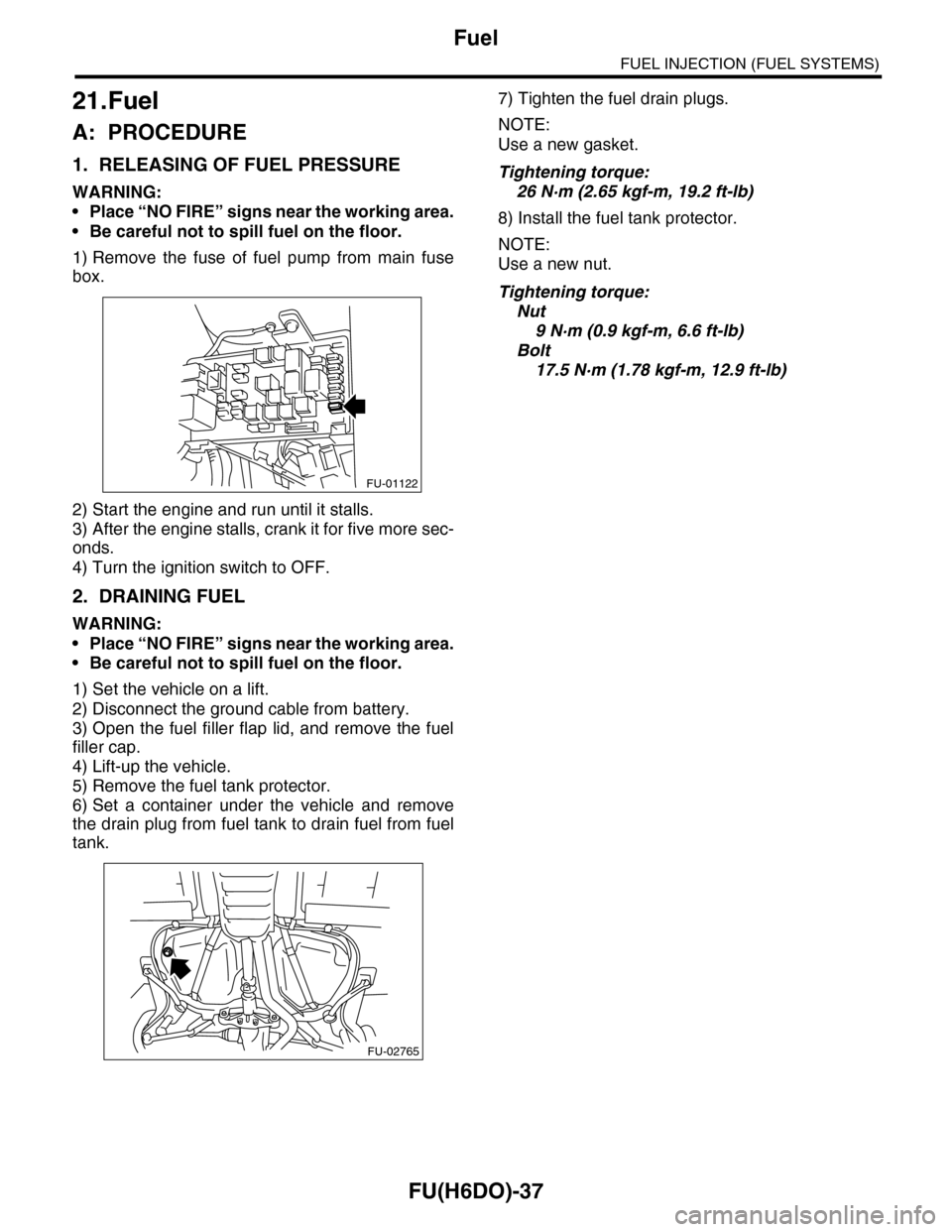
1) Remove the fuse of fuel pump from main fuse
box.
2) Start the engine and run until it stalls.
3) After the engine stalls, crank it for five more sec-
onds.
4) Turn the ignition switch to OFF.
2. DRAINING FUEL
WARNING:
•Place “NO FIRE” signs near the working area.
•Be careful not to spill fuel on the floor.
1) Set the vehicle on a lift.
2) Disconnect the ground cable from battery.
3) Open the fuel filler flap lid, and remove the fuel
filler cap.
4) Lift-up the vehicle.
5) Remove the fuel tank protector.
6) Set a container under the vehicle and remove
the drain plug from fuel tank to drain fuel from fuel
tank.
7) Tighten the fuel drain plugs.
NOTE:
Use a new gasket.
Tightening torque:
26 N·m (2.65 kgf-m, 19.2 ft-lb)
8) Install the fuel tank protector.
NOTE:
Use a new nut.
Tightening torque:
Nut
9 N·m (0.9 kgf-m, 6.6 ft-lb)
Bolt
17.5 N·m (1.78 kgf-m, 12.9 ft-lb)
FU-01122
FU-02765
Page 1609 of 2453
FU(H6DO)-48
Fuel Delivery, Return and Evaporation Lines
FUEL INJECTION (FUEL SYSTEMS)
28.Fuel Delivery, Return and Evaporation Lines
A: REMOVAL
1) Set the vehicle on a lift.
2) Release the fuel pressure.
3) Open the fuel filler flap lid, and remove the fuel filler cap.
4) Remove the floor mat.
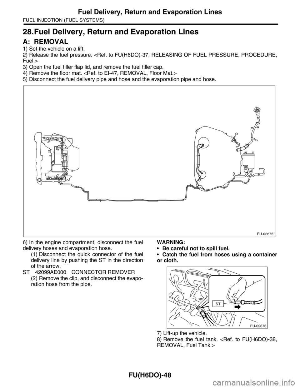
5) Disconnect the fuel delivery pipe and hose and the evaporation pipe and hose.
6) In the engine compartment, disconnect the fuel
delivery hoses and evaporation hose.
(1) Disconnect the quick connector of the fuel
delivery line by pushing the ST in the direction
of the arrow.
ST 42099AE000 CONNECTOR REMOVER
(2) Remove the clip, and disconnect the evapo-
ration hose from the pipe.
WARNING:
•Be careful not to spill fuel.
•Catch the fuel from hoses using a container
or cloth.
7) Lift-up the vehicle.
8) Remove the fuel tank.
FU-02675
Page 1610 of 2453
FU(H6DO)-49
Fuel Delivery, Return and Evaporation Lines
FUEL INJECTION (FUEL SYSTEMS)
9) Separate the quick connector of fuel line.
(1) Clean the pipe and connector, if they are
covered with dust.
(2) To prevent from damaging or entering for-
eign matter, wrap the pipes and connectors with
plastic bag etc.
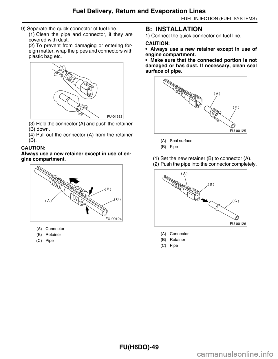
(3) Hold the connector (A) and push the retainer
(B) down.
(4) Pull out the connector (A) from the retainer
(B).
CAUTION:
Always use a new retainer except in use of en-
gine compartment.
B: INSTALLATION
1) Connect the quick connector on fuel line.
CAUTION:
•Always use a new retainer except in use of
engine compartment.
•Make sure that the connected portion is not
damaged or has dust. If necessary, clean seal
surface of pipe.
(1) Set the new retainer (B) to connector (A).
(2) Push the pipe into the connector completely.
(A) Connector
(B) Retainer
(C) Pipe
FU-01333
FU-00124
( A )
( B )
( C )
(A) Seal surface
(B) Pipe
(A) Connector
(B) Retainer
(C) Pipe
FU-00125
( A )
( B )
FU-00126
( A )
( B )
( C )
Page 1615 of 2453
GD(H6DO)-3
List of Diagnostic Trouble Code (DTC)
GENERAL DESCRIPTION
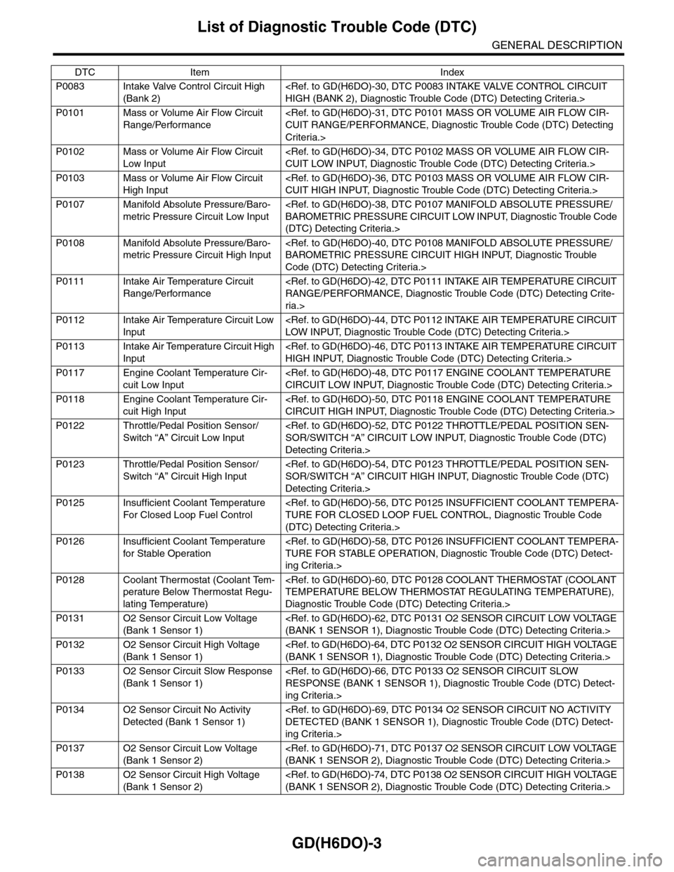
P0083 Intake Valve Control Circuit High
(Bank 2)
P0101 Mass or Volume Air Flow Circuit
Range/Performance
Criteria.>
P0102 Mass or Volume Air Flow Circuit
Low Input
P0103 Mass or Volume Air Flow Circuit
High Input
P0107 Manifold Absolute Pressure/Baro-
metric Pressure Circuit Low Input
(DTC) Detecting Criteria.>
P0108 Manifold Absolute Pressure/Baro-
metric Pressure Circuit High Input
Code (DTC) Detecting Criteria.>
P0111 Intake Air Temperature Circuit
Range/Performance
ria.>
P0112 Intake Air Temperature Circuit Low
Input
P0113 Intake Air Temperature Circuit High
Input
P0117 Engine Coolant Temperature Cir-
cuit Low Input
P0118 Engine Coolant Temperature Cir-
cuit High Input
P0122 Throttle/Pedal Position Sensor/
Switch “A” Circuit Low Input
Detecting Criteria.>
P0123 Throttle/Pedal Position Sensor/
Switch “A” Circuit High Input
Detecting Criteria.>
P0125 Insufficient Coolant Temperature
For Closed Loop Fuel Control
(DTC) Detecting Criteria.>
P0126 Insufficient Coolant Temperature
for Stable Operation
ing Criteria.>
P0128 Coolant Thermostat (Coolant Tem-
perature Below Thermostat Regu-
lating Temperature)
Diagnostic Trouble Code (DTC) Detecting Criteria.>
P0131 O2 Sensor Circuit Low Voltage
(Bank 1 Sensor 1)
P0132 O2 Sensor Circuit High Voltage
(Bank 1 Sensor 1)
P0133 O2 Sensor Circuit Slow Response
(Bank 1 Sensor 1)
ing Criteria.>
P0134 O2 Sensor Circuit No Activity
Detected (Bank 1 Sensor 1)
ing Criteria.>
P0137 O2 Sensor Circuit Low Voltage
(Bank 1 Sensor 2)
P0138 O2 Sensor Circuit High Voltage
(Bank 1 Sensor 2)
DTC Item Index
Page 1616 of 2453
GD(H6DO)-4
List of Diagnostic Trouble Code (DTC)
GENERAL DESCRIPTION
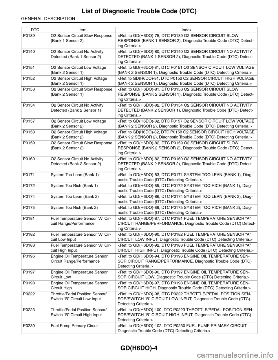
P0139 O2 Sensor Circuit Slow Response
(Bank 1 Sensor 2)
ing Criteria.>
P0140 O2 Sensor Circuit No Activity
Detected (Bank 1 Sensor 2)
ing Criteria.>
P0151 O2 Sensor Circuit Low Voltage
(Bank 2 Sensor 1)
P0152 O2 Sensor Circuit High Voltage
(Bank 2 Sensor 1)
P0153 O2 Sensor Circuit Slow Response
(Bank 2 Sensor 1)
ing Criteria.>
P0154 O2 Sensor Circuit No Activity
Detected (Bank 2 Sensor 1)
ing Criteria.>
P0157 O2 Sensor Circuit Low Voltage
(Bank 2 Sensor 2)
P0158 O2 Sensor Circuit High Voltage
(Bank 2 Sensor 2)
P0159 O2 Sensor Circuit Slow Response
(Bank 2 Sensor 2)
ing Criteria.>
P0160 O2 Sensor Circuit No Activity
Detected (Bank 2 Sensor 2)
ing Criteria.>
P0171 System Too Lean (Bank 1)
P0172 System Too Rich (Bank 1)
P0174 System Too Lean (Bank 2)
P0175 System Too Rich (Bank 2)
P0181 Fuel Temperature Sensor “A” Cir-
cuit Range/Performance
ing Criteria.>
P0182 Fuel Temperature Sensor “A” Cir-
cuit Low Input
P0183 Fuel Temperature Sensor “A” Cir-
cuit High Input
P0196 Engine Oil Temperature Sensor
Circuit Range/Performance
Detecting Criteria.>
P0197 Engine Oil Temperature Sensor
Circuit Low
P0198 Engine Oil Temperature Sensor
Circuit High
P0222 Throttle/Pedal Position Sensor/
Switch “B” Circuit Low Input
Detecting Criteria.>
P0223 Throttle/Pedal Position Sensor/
Switch “B” Circuit High Input
Detecting Criteria.>
P0230 Fuel Pump Primary Circuit
DTC Item Index